New simply node sensor project - please some advise
-
Hi there all,
because I love a lot this great project MySensor, I begin to work on a simply node sensor
in order to have my one and make as I like.Thi sensor will be a BME280 Temp/Humidity/Pressure sensor,
will work on ATMEGA328P and will transmit via RFM69 (cause I need big distances).
All will be power by 2 X 1.5 AAA battery, so I write the bootloader at 4 mHz in order to
suck more power from batts.
So I don't put a buster on this sensor.Here I paste the sensor at this point:
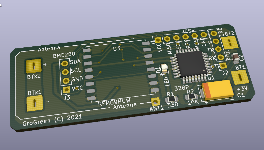
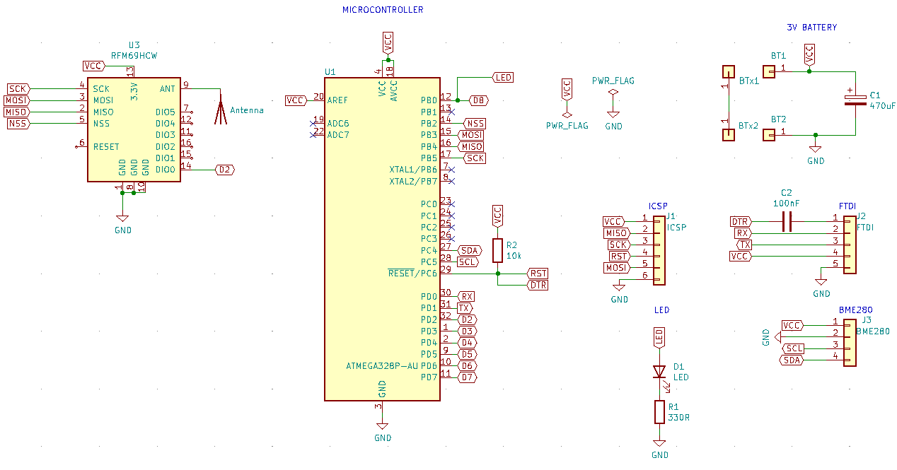
And here is the schema:
Because I'm beginner, in Arduino, in Kicad and all this thinks,
I want to ask you all to give me some advise on this minimal hardware.For example... I tested the sensor with a 10uF electrolytic capacitor
and I went at about 120 mt outside from my home. (gateway inside home)
Then I put a 1000uF (I have no other) capacitor and it work at about 150-170 mt.
So it'k ok the C1 at 470uF (!tantalum) on my schema ?
I also have read in some place that if the capacitor is bigger,
the sensor can use better the battery power every time that will wake up.So please tell me if I can make some change before sending to Jlcpcb to make and assembly the pieces.
Thanks all in advance
Denis -
Hi there all,
because I love a lot this great project MySensor, I begin to work on a simply node sensor
in order to have my one and make as I like.Thi sensor will be a BME280 Temp/Humidity/Pressure sensor,
will work on ATMEGA328P and will transmit via RFM69 (cause I need big distances).
All will be power by 2 X 1.5 AAA battery, so I write the bootloader at 4 mHz in order to
suck more power from batts.
So I don't put a buster on this sensor.Here I paste the sensor at this point:
And here is the schema:
Because I'm beginner, in Arduino, in Kicad and all this thinks,
I want to ask you all to give me some advise on this minimal hardware.For example... I tested the sensor with a 10uF electrolytic capacitor
and I went at about 120 mt outside from my home. (gateway inside home)
Then I put a 1000uF (I have no other) capacitor and it work at about 150-170 mt.
So it'k ok the C1 at 470uF (!tantalum) on my schema ?
I also have read in some place that if the capacitor is bigger,
the sensor can use better the battery power every time that will wake up.So please tell me if I can make some change before sending to Jlcpcb to make and assembly the pieces.
Thanks all in advance
Denis@DenisJ I can give 2 piexes of advice....
- Measure the current drawn by the radio module in transmit. Small batteries may not last long if it is too high (say more than 20-30mA).2,
- Do not use tantalum caps. They can have high ESR and have an ability to fail as a short circuit. Try ceramic SMD caps instead.
In this use case only - think of the cap as a little rechargeable battery that can provide current quickly for a short period of time when needed (during transmission) and then recharge over a short period of time after that.
-
@skywatch said in New simply node sensor project - please some advise:
Measure the current drawn by the radio module in transmit. Small batteries may not last long if it is too high (say more than 20-30mA).2,
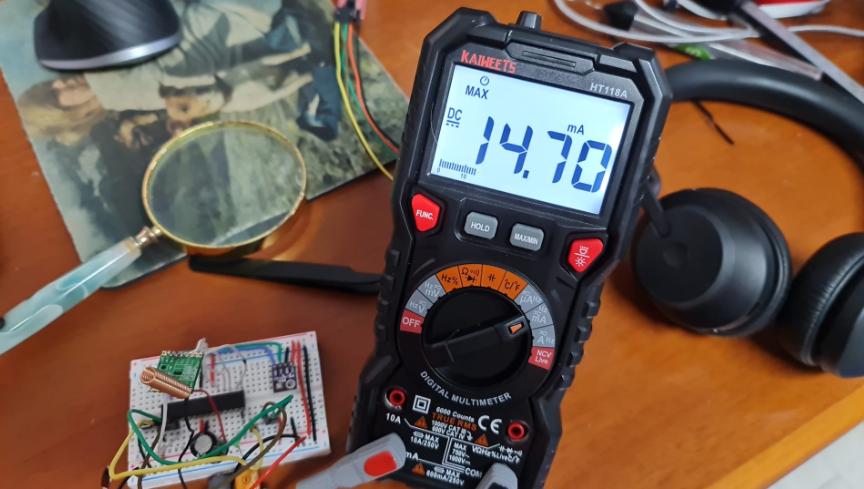
Do not use tantalum caps. They can have high ESR and have an ability to fail as a short circuit. Try ceramic SMD caps instead.I just misure the power consume of the RFM69 radio and it's around 15mA max:
So you think it's ok ?
This is the develop project and here I use the 1000uF electrolytic capacitor (don't know if in this case help the radio power)So for the cap please tell me... I must put a ceramic with out polarization ?
If yes, do you think this one it's ok please ? ...they have no disponibility for bigger than 220uFThanks a lot for your help
Denisp.s. in the mean time I found this one that have only 7 mΩ MSR
Do you think it's ok please ? -
@skywatch said in New simply node sensor project - please some advise:
Measure the current drawn by the radio module in transmit. Small batteries may not last long if it is too high (say more than 20-30mA).2,
Do not use tantalum caps. They can have high ESR and have an ability to fail as a short circuit. Try ceramic SMD caps instead.I just misure the power consume of the RFM69 radio and it's around 15mA max:
So you think it's ok ?
This is the develop project and here I use the 1000uF electrolytic capacitor (don't know if in this case help the radio power)So for the cap please tell me... I must put a ceramic with out polarization ?
If yes, do you think this one it's ok please ? ...they have no disponibility for bigger than 220uFThanks a lot for your help
Denisp.s. in the mean time I found this one that have only 7 mΩ MSR
Do you think it's ok please ?@DenisJ Depending on how often you intend to send data, it looks OK to me.
The capacitor you linked to is good too (if you put them in parallel the capacitance will add - like putting resistors in series adds). So you can always add another across the first if you find you need more - you just have to try it out.
-
Hi there all,
because I love a lot this great project MySensor, I begin to work on a simply node sensor
in order to have my one and make as I like.Thi sensor will be a BME280 Temp/Humidity/Pressure sensor,
will work on ATMEGA328P and will transmit via RFM69 (cause I need big distances).
All will be power by 2 X 1.5 AAA battery, so I write the bootloader at 4 mHz in order to
suck more power from batts.
So I don't put a buster on this sensor.Here I paste the sensor at this point:
And here is the schema:
Because I'm beginner, in Arduino, in Kicad and all this thinks,
I want to ask you all to give me some advise on this minimal hardware.For example... I tested the sensor with a 10uF electrolytic capacitor
and I went at about 120 mt outside from my home. (gateway inside home)
Then I put a 1000uF (I have no other) capacitor and it work at about 150-170 mt.
So it'k ok the C1 at 470uF (!tantalum) on my schema ?
I also have read in some place that if the capacitor is bigger,
the sensor can use better the battery power every time that will wake up.So please tell me if I can make some change before sending to Jlcpcb to make and assembly the pieces.
Thanks all in advance
Denis@DenisJ Do NOT leave out decoupling capacitors for the MCU, because you may run into stability issues without them. Ideally, you'd place one 100 nF MLCC as close as possible to every VCC pin. But in my experience it's fine to use one MLCC for the two VCC pins that are next to each other on the ATmega328P-AU and one MLCC for the AVCC pin.
It's also advised to connect AREF to ground through a 100 nF MLCC to make it more immune to noise if you are using the internal reference to read the battery voltage. Otherwise, if you don't use the ADC at all, just leave it unconnected.
@DenisJ said in New simply node sensor project - please some advise:
p.s. in the mean time I found this one that have only 7 mΩ MSR
Do you think it's ok please ?Pay closer attention to the specs of the parts you pick. This tantalum cap is rated for 1.8V only. It'll fail before you get your first measurements from this node.
If you choose to stick with tantalum for their compact size, opt for one that's rated for 10V, or maybe 6.3V. If you run them at 3V, they should be roughly in their "sweet spot" regarding DC leakage.
Speaking of leakage current: Larger capacitors should be able to help stabilize the voltage further when the RFM69 is transmitting, but the leakage current increases with larger capacity. A high leakage current can noticably cut down on the total battery lifetime, as a low current consumption during sleep is most important for long lasting batteries in devices like this.
Although the RFM69 will likely draw considerable more than your multimeter shows (I guess it's too slow to show the "real" peak current; IIRC datasheet states 45 mA peak for non-H RFM69 and up to 130 mA for the H version), I think about 470 µF should be a good compromise here.
If you don't mind the physically larger size, consider using an electrolytic capacitor instead. They are safer to use and usually achieve lower DC leakage currents. I can personally recommend the Nichicon UMA / UMR series. You may use the electrolytic (or tantalum) capacitor in conjunction with a lower capacity (~10 µA) MLCC.
You could also get a few large capacity MLCCs instead of the tantalum, as @skywatch suggested. With MLCCs you typically don't have to worry about DC leakage, but note that their operating capacity reduces drastically, the closer the applied voltage is to their rated voltage. For example, a 100 µF MLCC rated for 6.3V may only have 60µF at 3V or 30µF at 6V. But you can always add multiple in parallel.
Those are all viable options.
-
Oh boys... a lot of information here.
Thanks so much... but I've already place the pcb order... I have make an order for 10 pieces. :-(
Bun in the mean time I'll experiment and modify the schema thanks to you all :-)Anyway I have placed there this capacitor ... I hope will be ok for this time.
Thanks so much for all information
Denis
Hello! It looks like you're interested in this conversation, but you don't have an account yet.
Getting fed up of having to scroll through the same posts each visit? When you register for an account, you'll always come back to exactly where you were before, and choose to be notified of new replies (either via email, or push notification). You'll also be able to save bookmarks and upvote posts to show your appreciation to other community members.
With your input, this post could be even better 💗
Register Login