My Wemos D1 mini adventures - Interrupts on pins D3 and D4
-
Hi all,
Recently I started to experiment with the Wemos D1 mini as a MySensors node, with a NRF24L01+ radio. As most wouldn't go this route, since it has built in WiFi. I did, because for one WiFi was not available for the particular node I'm developing. And second I don't really like my HA to run on WiFi. There are many reasons I have for this. But my main concern is the amount of time it takes to reconfigure all your nodes when the ssid and or password on your router have changed. But let's not start a topic on this. In this topic I just wanted to share some tips and tricks I discovered which some were hard to find on the internet and others I came up with my own solution. I'll keep adding tips and tricks to this topic if I discover new ones.
The Mini D1 doesn't like it when you declare an interrupt handler like you'd normally do.
volatile bool interruptReceived= false;

void handleInterrupt() {
  interruptReceived = true;
}
If you're lucky it compiles. But it will not work. You'll receive a strange bootloader error and the Mini will not boot. The reason for this is that the Mini expects handlers to be stored in the IRAM space. Just add a compiler directive and your interrupt handler will work just fine.
volatile bool interruptReceived= false;

ICACHE_RAM_ATTR void handleInterrupt() {
  interruptReceived = true;
}

void setup() {
    pinMode( interruptPin, INPUT_PULLUP );
    attachInterrupt(digitalPinToInterrupt( interruptPin ), handleInterrupt, FALLING );
Be carefull with using interrupts on D3 and D4
So the ESP2866 does a lot of funky things during bootup. It will pull some pins HIGH and LOW to check if it should go into program mode or not. It probably uses it for more reasons, but I'm by no means an ESP expert. The D3 and D4 pins are pulled up high by the Esp, with a - I believe - 10K resistor. Whenever you connect anything to it, that will cause these pins to be high during booting, the Wemos will not finish the boot mode and your sketch is never loaded.
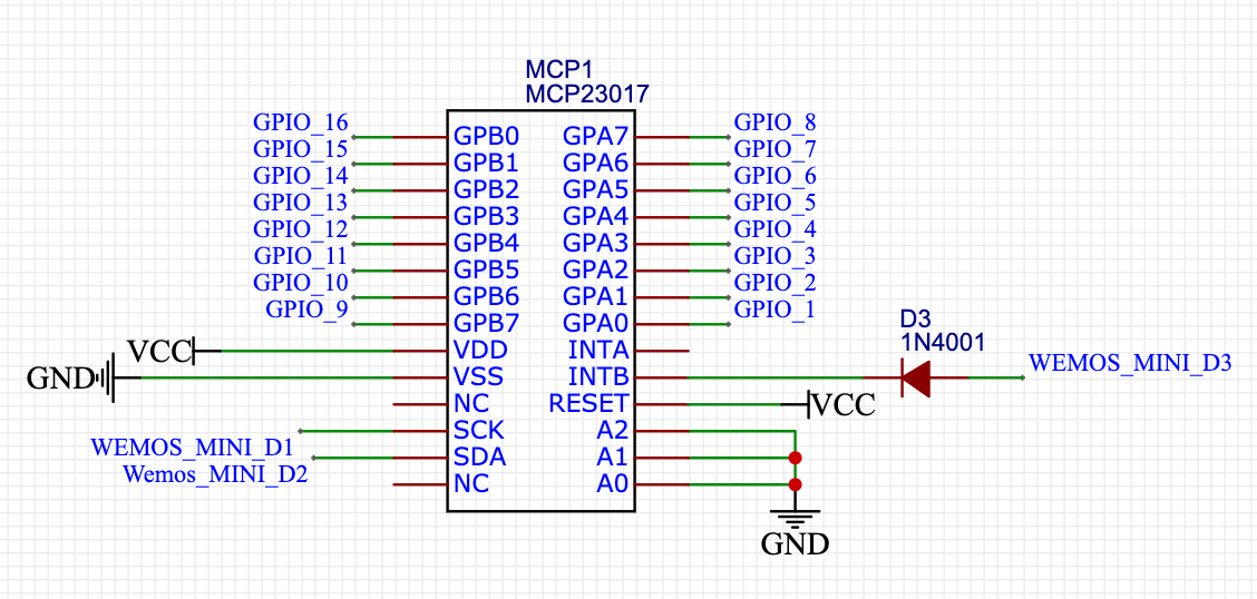
I wanted to attach an MCP23017 port extender to my Wemos and use the interrupt to refresh the values. So I didn't need to poll the MCP23017 all of the time and kept CPU time available for other tasks. The problem with this, is that the MCP23017 pulls it's interrupt pin HIGH when there's no interrupt - which is always the case when the chip power's up. So connecting the interrupt pin to D3 or D4 caused my Mini D1 to not exit boot mode.
I could have simply used D3 and D4 as SDA and SCL pins for the I2c communications and use D1 and D2 as interrupt pins. But not all libraries like that. So the easiest way to get around it was a simple and cheap hardware solution. I connected a diode (doesn't matter which one you take. Just take a low 1N400x one) and that did the following:
The HIGH value of the MCP's interrupt pin is blocked by the diode. When the MCP pulls the interrupt pin low current can flow between the interrupt pin (INPUT_PULLUP) on the Wemos Mini and the MCP's interrupt pin. This made sure the MCP is never able to pull the pin on the Mini high. And the problem was actually solved - easy peasy. I can use D3 and D4 as interrupt pins.Here's the schematic. In my case I use the mirror mode on the MCP's interrupts. So I only need to connect one of the MCP23017's interrupt pins to the Wemos.

I also run the MCP23017 on 3.3V so it's the same as the Wemos mini. -
While we're at this topic. Does any one know what the NRF24L01+ does with it's interrupt pin? I'd like to hook it up to the other pin - d4 in this case. Does it pull high when there's a new message or is it pulled up by default? Which I hope
