💬 Version 3.0 atmega328p test platform
-
After looking at it again with fresh eyes, I've decided to do a version 3. It will drop two of the 10K resistors because they are probably overkill. Also, I'll add to the silkscreen so that it will be more self-documenting than the present version as to which pins are what. I may or may not fiddle just a tad with the spacing on the two AA batteries to make it a bit more symmetric, but it's going to be tight no matter what I do in order to avoid changing the spacing on the radio shields. However, with the switch now gone, it will be easier to add in a separator between the two batteries if needed.
If I had never posted the files I probably wouldn't be doing any of this, but now that it's posted, Ill do a give-back to the community by putting it into a more polished state rather than just leave it as is.
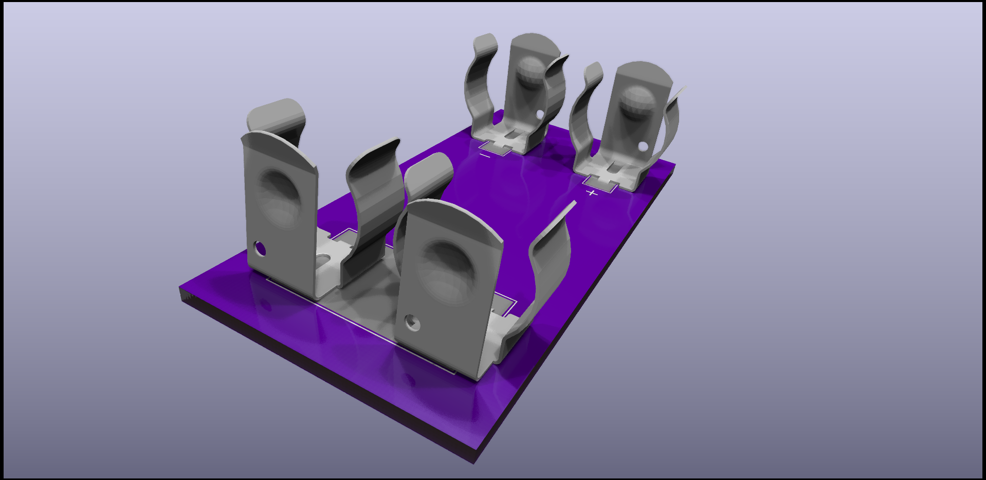
@NeverDie I hit up Keystone Electronics for a 3D model of the battery clip (p/n 92) and then did a little work on setting up 3D models of 2 and 4 of them together - though the 4-piece model is based on the spacing of 16.8mm between centres. If you're interested, I'll share them in a Github repository, since I can't upload them here.
-
@NeverDie I hit up Keystone Electronics for a 3D model of the battery clip (p/n 92) and then did a little work on setting up 3D models of 2 and 4 of them together - though the 4-piece model is based on the spacing of 16.8mm between centres. If you're interested, I'll share them in a Github repository, since I can't upload them here.
@alphaHotel said in 💬 Version 2.0 atmega328p test platform:
@NeverDie I hit up Keystone Electronics for a 3D model of the battery clip (p/n 92) and then did a little work on setting up 3D models of 2 and 4 of them together - though the 4-piece model is based on the spacing of 16.8mm between centres. If you're interested, I'll share them in a Github repository, since I can't upload them here.
Yes, please! Sounds like it may be very useful!
-
@alphaHotel said in 💬 Version 2.0 atmega328p test platform:
@NeverDie I hit up Keystone Electronics for a 3D model of the battery clip (p/n 92) and then did a little work on setting up 3D models of 2 and 4 of them together - though the 4-piece model is based on the spacing of 16.8mm between centres. If you're interested, I'll share them in a Github repository, since I can't upload them here.
Yes, please! Sounds like it may be very useful!
@NeverDie said in 💬 Version 2.0 atmega328p test platform:
Yes, please! Sounds like it may be very useful!
Here's the repo. I only just now created the footprint for the 2-clip version so check measurements and such. Also, when I attach the 3D model to the footprint, I had to change the orientation 180 degrees and offset it by the thickness of the board and had to scale it 0.4 in X, Y, and Z dimensions. Hope it helps.
-
After looking at it again with fresh eyes, I've decided to do a version 3. It will drop two of the 10K resistors because they are probably overkill. Also, I'll add to the silkscreen so that it will be more self-documenting than the present version as to which pins are what. I may or may not fiddle just a tad with the spacing on the two AA batteries to make it a bit more symmetric, but it's going to be tight no matter what I do in order to avoid changing the spacing on the radio shields. However, with the switch now gone, it will be easier to add in a separator between the two batteries if needed.
If I had never posted the files I probably wouldn't be doing any of this, but now that it's posted, Ill do a give-back to the community by putting it into a more polished state rather than just leave it as is.
@NeverDie I wanted to have a closer look at your rev 2 but didn't see a RAR archive of the Kicad project. Don't upload it now though, I can wait for rev 3 for that. In looking at the schematic though, a question came to mind. What's the purpose of the 2 zero ohm bridging resistors, R6 & R7 in the schematic? Could you use a solder jumper/bridge there instead for the same purpose?
-
@NeverDie I wanted to have a closer look at your rev 2 but didn't see a RAR archive of the Kicad project. Don't upload it now though, I can wait for rev 3 for that. In looking at the schematic though, a question came to mind. What's the purpose of the 2 zero ohm bridging resistors, R6 & R7 in the schematic? Could you use a solder jumper/bridge there instead for the same purpose?
@alphaHotel said in 💬 Version 2.0 atmega328p test platform:
Could you use a solder jumper/bridge there instead for the same purpose?
Yes. Solder bridge would serve the same purpose. They're onlly there in case you don't have any interest in measuring current and, thus, don't care to install the 4 header pins or the header pin jumpers.
-
@NeverDie said in 💬 Version 2.0 atmega328p test platform:
Yes, please! Sounds like it may be very useful!
Here's the repo. I only just now created the footprint for the 2-clip version so check measurements and such. Also, when I attach the 3D model to the footprint, I had to change the orientation 180 degrees and offset it by the thickness of the board and had to scale it 0.4 in X, Y, and Z dimensions. Hope it helps.
@alphaHotel said in 💬 Version 2.0 atmega328p test platform:
had to scale it 0.4 in X, Y, and Z dimensions
Update: That's only with the WRL (VRML) files as that file format is "dimensionless" it seems. I'm just learning FreeCAD for manipulating these 3D models so this is my learning curve. The preferred 3D model for CAD programs is STEP and with those, I didn't have to scale or more precisely the scaling factor is the default 1.0. I may remove the WRL files from the repo.
-
@alphaHotel said in 💬 Version 2.0 atmega328p test platform:
Could you use a solder jumper/bridge there instead for the same purpose?
Yes. Solder bridge would serve the same purpose. They're onlly there in case you don't have any interest in measuring current and, thus, don't care to install the 4 header pins or the header pin jumpers.
@NeverDie said in 💬 Version 2.0 atmega328p test platform:
They're onlly there in case you don't have any interest in measuring current and, thus, don't care to install the 4 header pins or the header pin jumpers.
Thank you for providing this insight. I enjoy learning by trying to understand someone else's perspective. It's not always provided as clearly or freely as you have (and do). Very much appreciated.
-
I suppose an alternative would be to omit them entirely, and then if you didn't want to use the header pins, you could just short across the header pads instead. That would be more minimalist, and so more simple and so better. So, I think I'll omit them on version 3.
-
I suppose an alternative would be to omit them entirely, and then if you didn't want to use the header pins, you could just short across the header pads instead. That would be more minimalist, and so more simple and so better. So, I think I'll omit them on version 3.
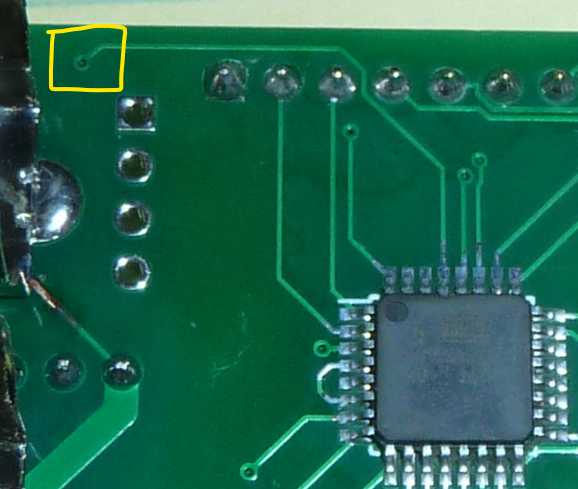
@NeverDie In considering a version 3, please consider turning the via in the following picture into a through-hole. it would allow for easier connection of a reset pin if needed to program the 328p with a programmer.
-
@NeverDie In considering a version 3, please consider turning the via in the following picture into a through-hole. it would allow for easier connection of a reset pin if needed to program the 328p with a programmer.
@alphaHotel You mean a single through-hole for the reset that you could latch onto with maybe a test probe hook/grabber? Yes, that seems like a good idea.
-
@NeverDie In considering a version 3, please consider turning the via in the following picture into a through-hole. it would allow for easier connection of a reset pin if needed to program the 328p with a programmer.
@alphaHotel OK, I squeezed one in for you, near the corner, where it will be easy to attach your hook/grabber:
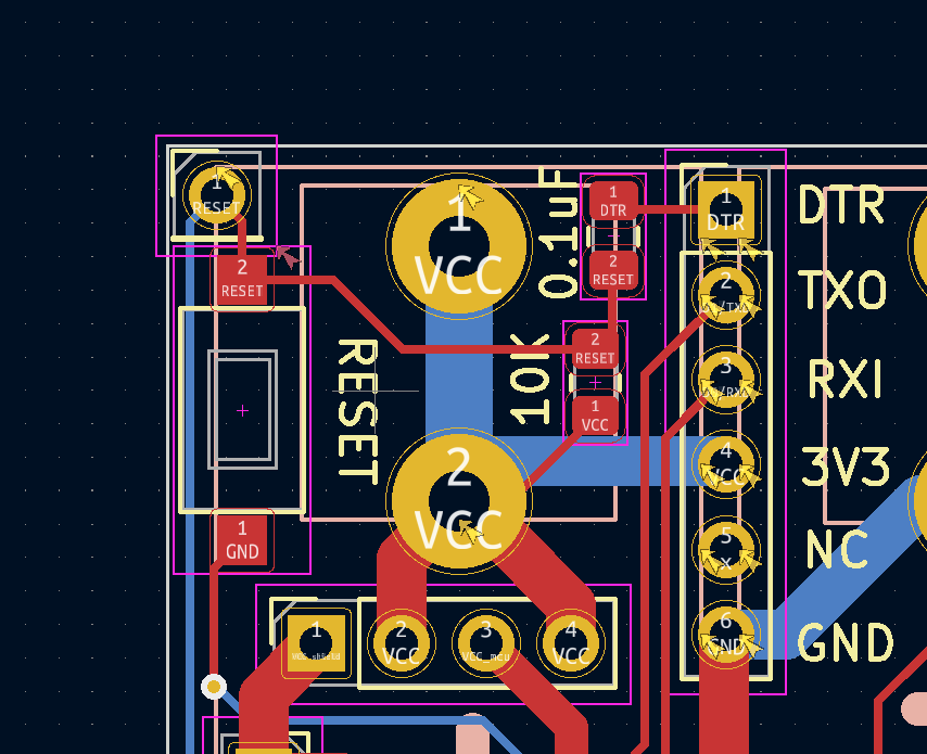
Technically speaking the courtyards overlap, but I'm going to ignore that technical error, as there just isn't much wiggle room. -
@alphaHotel OK, I squeezed one in for you, near the corner, where it will be easy to attach your hook/grabber:
Technically speaking the courtyards overlap, but I'm going to ignore that technical error, as there just isn't much wiggle room. -
@NeverDie Awesome. thanks.
@alphaHotel said in 💬 Version 3.0 atmega328p test platform:
@NeverDie Awesome. thanks.
I uploaded the files for version 3.0, including the KiCad 6.0 project archive as a .zip file contained within the .rar file. As it has already served its purpose for me, I didn't meddle with the spacing on the batteries, but I did go out of my way to avoid possible short-circuits between the battery holder and traces on the PCB.
Enjoy!