
WIP: My first PCB: Arduino Pro Mini + RFM69 small node (feedback wanted)
-
Hi,
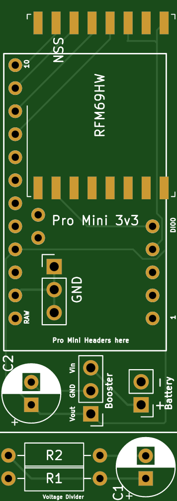
To increase the WAF of my door/window sensors I created this small PCB. It connects a RFM69 to an Arduino Pro Mini with the lowest footprint I could come up with. There is additional space for a booster and a voltage divider though the voltage divider is optional (Just cut it if you don't need it).
Criticism/Feedback and everything in between is very much welcome since I literally have no idea what I am doing and I hope somebody can point out issues before I order my first batch. So: so far this is untested, please don't order it until I got my hands on the first batch.
I was also hoping that somebody could tell me how to set up the project so that mysensors gets a few dollars for every ordered batch, I've seen other projects do that and I want to give back to the community too.
If, unexpectedly, there are no issues with the PCB the next step in the project will be to create a 3D-printable enclosure (I am leaning towards tinkercad, but again, I have no idea what I am doing and I am open to suggestions).
-
Hi,
To increase the WAF of my door/window sensors I created this small PCB. It connects a RFM69 to an Arduino Pro Mini with the lowest footprint I could come up with. There is additional space for a booster and a voltage divider though the voltage divider is optional (Just cut it if you don't need it).
Criticism/Feedback and everything in between is very much welcome since I literally have no idea what I am doing and I hope somebody can point out issues before I order my first batch. So: so far this is untested, please don't order it until I got my hands on the first batch.
I was also hoping that somebody could tell me how to set up the project so that mysensors gets a few dollars for every ordered batch, I've seen other projects do that and I want to give back to the community too.
If, unexpectedly, there are no issues with the PCB the next step in the project will be to create a 3D-printable enclosure (I am leaning towards tinkercad, but again, I have no idea what I am doing and I am open to suggestions).
@kiesel Looks like you are well on your way.
If you post a schematic, you'll likely get more feedback.
If you are using one of those Chinese step up converters to 3.3V, I found I had to add a 1 uF cap on Vin to get good performance at no load.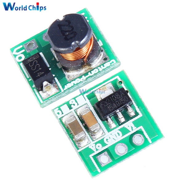
Most designs I've seen also have a 0.1 uF decoupling cap at the power connections to the radio.
I can't tell where you are connecting the door switch, directly to an unused pins on the pro mini?
One limitation to the pro mini is that you only have 2 interrupts and 1 is used for the radio, leaving you 1 for your project, which is probably fine for your application.
If you used a pro micro (32U4) instead, you would have 5 interrupts, leaving 4 for your project. And I don't think I've ever seen an rfm69 board for the pro micro, so it would be a first. Just a thought. -
@kiesel Looks like you are well on your way.
If you post a schematic, you'll likely get more feedback.
If you are using one of those Chinese step up converters to 3.3V, I found I had to add a 1 uF cap on Vin to get good performance at no load.Most designs I've seen also have a 0.1 uF decoupling cap at the power connections to the radio.
I can't tell where you are connecting the door switch, directly to an unused pins on the pro mini?
One limitation to the pro mini is that you only have 2 interrupts and 1 is used for the radio, leaving you 1 for your project, which is probably fine for your application.
If you used a pro micro (32U4) instead, you would have 5 interrupts, leaving 4 for your project. And I don't think I've ever seen an rfm69 board for the pro micro, so it would be a first. Just a thought.Thank you for your feedback!
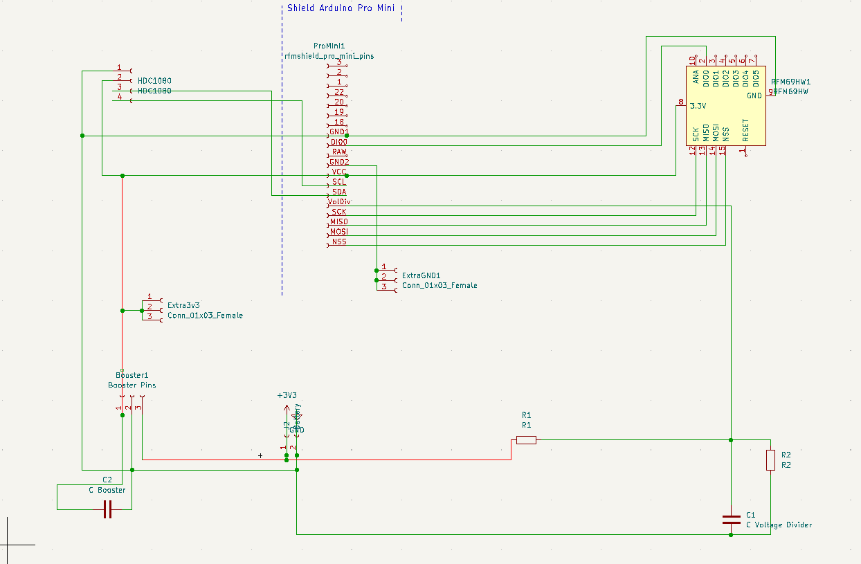
I have (or at least I think) a decoupling cap on the pcb (C2). And you are right, I should have added the schematics from the start.
I tried doing it on openhardware.io but now the pics of the pcb itself show an older version (the schematics are fine though, I'll add them here too).
I added pins for a HDC1080 temperature/humidity sensor, because that's what I'll probably end up adding anway.
1 interrupt should be all that I need, but if I need more I'll probably use this workaround. But thank you for letting me know about the micro, didn't even know that existed :)
-
-
@kiesel Thanks for the schematic.
For the decoupling cap, it should be as close to the 3.3V & Gnd pins of the radio as possible.
Keep us posted, thanks.
Hello! It looks like you're interested in this conversation, but you don't have an account yet.
Getting fed up of having to scroll through the same posts each visit? When you register for an account, you'll always come back to exactly where you were before, and choose to be notified of new replies (either via email, or push notification). You'll also be able to save bookmarks and upvote posts to show your appreciation to other community members.
With your input, this post could be even better 💗
Register Login