A low cost energy meter
-
I am curious to know if my heat pump is actually saving energy. To know this, I would need an energy meter. So I designed and built one. You can see my projoect and I believe it is sufficiently documented for you to build your own. See Energy Meter
My nephew has done the same and is as curious as I. But he knows nothing of MySensors, and how to get the data presented in a reasonable way. I explained to him it is a small matter. This turns out to be not so. Beyond the aforementioned energy meter, it involves an Arduino MySensors Gateway (hardware and software), Home Assistant (software), Virtual Box (Software), and an i86 computer (hardware) which is running linux (software). Just writing that makes the project sound intimidating. It is not, if you break it down to its constituent parts.
The Arduino Serial Gateway (GatewaySerial) can be found as an example in the Arduino IDE, once the Arduino library is loaded. This probrammed Arduino will be connected to the target computer vie the same USB cable used to program the arduino. For my environment, I have some modifications. The wiring of the radio to the Arduino Nano is slightly different. CE is wired to D10 and CS is wired to D9. Also, I am using radio channel 86. These changes are reflected in the following three lines which are added after the line
#define MY_RADIO_RF24#define MY_RF24_CS_PIN 9 // for compatibility with RF-Nano #define MY_RF24_CE_PIN 10 // for compatibility with RF-Nano #define MY_RF24_CHANNEL 86 // 86 is the development channel 121 is the production channelAcquiring an adequate computer for the task can be as simple ordering one from Amazon for around UD$85. Discarded laptops can be found for as little $10 sans battery and power supply. The only important requirement is more than 2GB RAM.
See information about SSH below
Installing Ubuntu on the computer is tedious but easily done. These instructions are for the server version of the operating system (OS). This version has no graphical user interface (GUI). You will need a monitor and a keyboard. If network manager is not installed (nmcli d doesn’t work) or nmcli d doesn’t indicate a wireless network, the internet port will have to be used. If there is only WiFi, a network client device, which connects to the internet port, will have to be used. Official instructions
Installing Virtual Box is also a tedious task. By this time you’re pretty used to using the command line.
Finally, installing Home Assistant will be the training session for working with Home Assistant.
Information about SSH
SSH is programs running on your usual desktop computer and the target computer. When you installed the operating system on the target computer, you entered a username and and password. Once the target computer is up and running, and you’ve found it’s IP address (ip address) you can “ssh” from your usual desktop with “ssh username@xxx.xxx.xxx.xxx (the IP address you just found) You will be prompted for the password.This is just like being at the keyboard and monitor of your target computer. EXCEPT, you can now copy and paste from your usual desktop computer into the window of the target computer. That is, you don’t have to fret about typing in all those commands.
Challenge yourself! :) It's all do-able and you can do it!
OSD
The answer to your first question is, "Yes, you can do it!"
-
Hi OldSurferDude,
I just read through your Energy Meter documentation. Nice work. It gives basic theory and calculations. I've been thinking about building an energy meter for a while now. I'll use this as a reference. Thanks.@KevinT you welcome :)
-
I saw on your git page that you were looking for a HW.
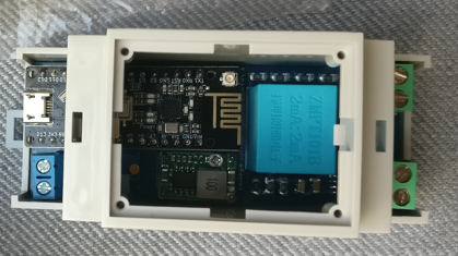
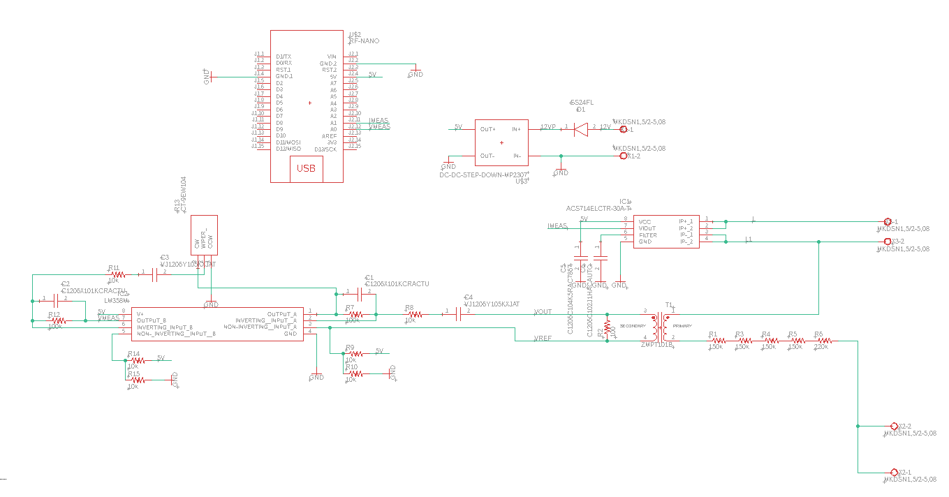
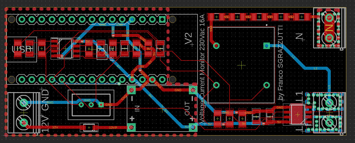
@OldSurferDude would something like this work ? The schematic is very similar.
I would just need to move the current sensor a bit far from the connector, in case of a new PCB order is required
-
I like the work you've done! Making a schematic which can be made into a PCB is a skill that I have yet to acquire.
I appreciate that you have shown me (us) this design, for it gave me serious pause to think. While I point out some areas that would suggest review, I would encourage you fully document what you've done and put it on git.
I checked out the ACS714ELCTR device and, if I understand it correctly, it has to be in series with the heat pump. The wire to the heat pump is 6AWG (50A). So, yes, the current sensor would have to have it's own PCB with suitable trace widths and separation and high current connectors. The resistance of the sensor is negligible (1.2 mΩ) compared to that of the connectors. (20 mΩ); Even 5mΩ @30A is 4.5W and the sensor is cooking away at 1W!
One of the concerns I pointed out was that my design probably would nullify one's homeowner's insurance. An in-line with a 50A circuit, would be a greater concern.
Is the current output the instantaneous current? "5 µs output rise time in response to step input current" Implies that it is, compared to the ~100µs that it takes for the Arduino to read the analog port.
The sensor reports the current as proportional to an positive analog voltage. This means that the output would look like a full wave rectified AC signal. Determining phase angle Φ would involve noting the time of lowest current comparted to the time of lowest voltage as opposed to zero crossing. In this case, one wouldn't know if that was leading a lot or lagging a little (or vice versa), though practical assumptions could be made.
One of the things that the people at Open Energy are troubled with is distortion. The energy AC sign wave is not truly a sign wave, typically there is a flattening at the top. Pumps can cause a very distorted signal! But the concern here is, "How much distortion does your measuring device introduce?" In my device, and this would be true of yours, too. there is the ~100µs between voltage and current readings and an additional ~70µs computational time. But chasing down those problems are not the concern of the low cost meters you and I designed. :)
Good work!
OSD
@OldSurferDude yes, you are correct. this sensor is capable of 50A continuous, which safely I would make it working at 40A max., but for such an important load as in your case I would go for a beefier one, like the ACS75x, 77x, but at this point I would also change the node's form factor for space and insulation reasons.
On my application on the RV I have a max. curr. of 13A running on a AWG14-16 cable (European rules for RVs), so I did not ask myself too many questions beside, of course, safety.
About the signal, it will be a sinusoidal signal swinging around Vcc/2.
Vcc can be easily measured internally on the ATmega328. On all my DC sensors I measure Vcc at every loop, just before measuring the ADCs.Honestly, when the space is not an issue like in my RV, I would rather use a ring core current transformer, and I would get rid of noise, response time, power dissipation, but over all no need to cut any cable.
Long story short, it has been a nice experiment and I used it for 6 months, and then I switched back to my RF-NANO based RS485-Modbus - Mysensors bridge connected to an off-the shelf power analyzer.
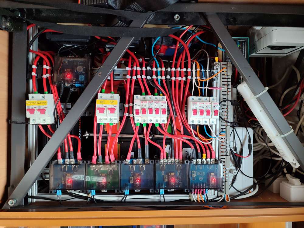
Just for fun I attach a pic of my 12Vdc sensors installed on my RV. Forgive me for the spaghetti wiring on the right side, but this is an area that needs improvement.
Hello! It looks like you're interested in this conversation, but you don't have an account yet.
Getting fed up of having to scroll through the same posts each visit? When you register for an account, you'll always come back to exactly where you were before, and choose to be notified of new replies (either via email, or push notification). You'll also be able to save bookmarks and upvote posts to show your appreciation to other community members.
With your input, this post could be even better 💗
Register Login