Skip to content
  • MySensors
  • OpenHardware.io
  • Categories
  • Recent
  • Tags
  • Popular
Skins
  • Light
  • Brite
  • Cerulean
  • Cosmo
  • Flatly
  • Journal
  • Litera
  • Lumen
  • Lux
  • Materia
  • Minty
  • Morph
  • Pulse
  • Sandstone
  • Simplex
  • Sketchy
  • Spacelab
  • United
  • Yeti
  • Zephyr
  • Dark
  • Cyborg
  • Darkly
  • Quartz
  • Slate
  • Solar
  • Superhero
  • Vapor

  • Default (No Skin)
  • No Skin
Collapse
Brand Logo
  1. Home
  2. Troubleshooting
  3. 433MHz amplified (>5V)

433MHz amplified (>5V)

Scheduled Pinned Locked Moved Troubleshooting
22 Posts 4 Posters 11.5k Views 3 Watching
  • Oldest to Newest
  • Newest to Oldest
  • Most Votes
Reply
  • Reply as topic
Log in to reply
This topic has been deleted. Only users with topic management privileges can see it.
  • A Offline
    A Offline
    andriej
    wrote on last edited by
    #5

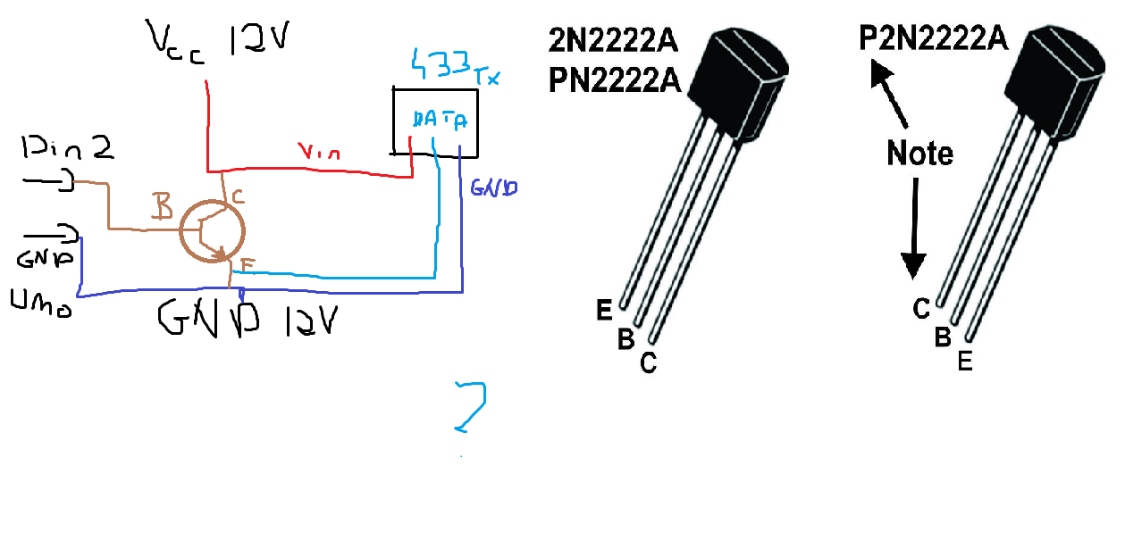
    I got the PN2222A but I struggle what should be connected to emitter, base and collector. What my thougt was: emitter to Data pin, collector to Vcc of 12v supply and base to arduino data pin, no resistors used.
    But should the gnd be both connected? And Vcc of 433 TX is connected to +12v power supply.
    It is Uno so I can power it with usb separately.

    :-)

    1 Reply Last reply
    0
    • A Offline
      A Offline
      andriej
      wrote on last edited by
      #6

      This is how I see it - is it proper idea?idea.png

      :-)

      SparkmanS 1 Reply Last reply
      0
      • A andriej

        This is how I see it - is it proper idea?idea.png

        SparkmanS Offline
        SparkmanS Offline
        Sparkman
        Hero Member
        wrote on last edited by Sparkman
        #7

        @andriej That's not the right way as there's nothing (other than the transistor) limiting the current between Vcc and GND. What you need to do is level shift the output of Pin 2 (0 to 5V) to the data input of the 433 module. The best way to level shift would be to do something like this:

        level shift.gif

        See http://electronics.stackexchange.com/questions/17581/best-way-to-get-5v-or-12v-or-0v-from-arduino-pin for details on this circuit.

        Cheers
        Al

        A 1 Reply Last reply
        0
        • SparkmanS Sparkman

          @andriej That's not the right way as there's nothing (other than the transistor) limiting the current between Vcc and GND. What you need to do is level shift the output of Pin 2 (0 to 5V) to the data input of the 433 module. The best way to level shift would be to do something like this:

          level shift.gif

          See http://electronics.stackexchange.com/questions/17581/best-way-to-get-5v-or-12v-or-0v-from-arduino-pin for details on this circuit.

          Cheers
          Al

          A Offline
          A Offline
          andriej
          wrote on last edited by
          #8

          @Sparkman thank you for your reply!
          So I'd need two transistors - that's ok... But how (and which one) do I connect to DATA pin (as I assume)?
          Or i could bridge P1 and P2 mentioned on schematics above?

          :-)

          SparkmanS 1 Reply Last reply
          0
          • A andriej

            @Sparkman thank you for your reply!
            So I'd need two transistors - that's ok... But how (and which one) do I connect to DATA pin (as I assume)?
            Or i could bridge P1 and P2 mentioned on schematics above?

            SparkmanS Offline
            SparkmanS Offline
            Sparkman
            Hero Member
            wrote on last edited by
            #9

            @andriej P1 would connect to the data pin. Ignore P2 as it is just ground.

            Cheers
            Al

            A 1 Reply Last reply
            0
            • SparkmanS Sparkman

              @andriej P1 would connect to the data pin. Ignore P2 as it is just ground.

              Cheers
              Al

              A Offline
              A Offline
              andriej
              wrote on last edited by
              #10

              @Sparkman Right, now I see.
              Will NPN (2N2222 which I have) do the job?

              :-)

              SparkmanS 1 Reply Last reply
              0
              • A andriej

                @Sparkman Right, now I see.
                Will NPN (2N2222 which I have) do the job?

                SparkmanS Offline
                SparkmanS Offline
                Sparkman
                Hero Member
                wrote on last edited by Sparkman
                #11

                @andriej It'll do the job of Q1, but Q2 is a PNP transistor. For it you would need something like the 2N2907, 2N3906 or 2N4403.

                A 1 Reply Last reply
                0
                • SparkmanS Sparkman

                  @andriej It'll do the job of Q1, but Q2 is a PNP transistor. For it you would need something like the 2N2907, 2N3906 or 2N4403.

                  A Offline
                  A Offline
                  andriej
                  wrote on last edited by andriej
                  #12

                  @Sparkman time for getting parts as I don't have PNP in house.
                  Thank you. :-) Tommorow I'll test it out.

                  Just to be 100% sure - both GND's should be connected together (Uno's and 12V supply?)

                  :-)

                  SparkmanS 1 Reply Last reply
                  0
                  • A andriej

                    @Sparkman time for getting parts as I don't have PNP in house.
                    Thank you. :-) Tommorow I'll test it out.

                    Just to be 100% sure - both GND's should be connected together (Uno's and 12V supply?)

                    SparkmanS Offline
                    SparkmanS Offline
                    Sparkman
                    Hero Member
                    wrote on last edited by
                    #13

                    @andriej said:

                    Just to be 100% sure - both GND's should be connected together (Uno's and 12V supply?)

                    Yes, that's correct.

                    Cheers
                    Al

                    A 1 Reply Last reply
                    0
                    • SparkmanS Sparkman

                      @andriej said:

                      Just to be 100% sure - both GND's should be connected together (Uno's and 12V supply?)

                      Yes, that's correct.

                      Cheers
                      Al

                      A Offline
                      A Offline
                      andriej
                      wrote on last edited by
                      #14

                      @Sparkman thank you very much, it worked absolutely flawless. I can now again control the switches, will test it with different voltages and antennas.

                      One more thing - I've read some time ago that it might be worth considering a capacitor (polarized one) at least 10uF conected to transmitter's Vcc and GND.
                      Do you think it could stabilize power and smooth it even more, so the quality of signal and strenght could be even better?

                      As a antenna currently I use the core from coax tv cable, 174mm long - straight without any shielding.

                      Regards

                      :-)

                      SparkmanS 1 Reply Last reply
                      0
                      • A andriej

                        @Sparkman thank you very much, it worked absolutely flawless. I can now again control the switches, will test it with different voltages and antennas.

                        One more thing - I've read some time ago that it might be worth considering a capacitor (polarized one) at least 10uF conected to transmitter's Vcc and GND.
                        Do you think it could stabilize power and smooth it even more, so the quality of signal and strenght could be even better?

                        As a antenna currently I use the core from coax tv cable, 174mm long - straight without any shielding.

                        Regards

                        SparkmanS Offline
                        SparkmanS Offline
                        Sparkman
                        Hero Member
                        wrote on last edited by
                        #15

                        @andriej Glad to hear it's working. A capacitor between Vcc an GND can help smooth any ripple. It won't hurt to add it if you have one kicking around.

                        Cheers
                        Al

                        A 1 Reply Last reply
                        0
                        • SparkmanS Sparkman

                          @andriej Glad to hear it's working. A capacitor between Vcc an GND can help smooth any ripple. It won't hurt to add it if you have one kicking around.

                          Cheers
                          Al

                          A Offline
                          A Offline
                          andriej
                          wrote on last edited by
                          #16

                          @Sparkman strange thing happened and suddenly everything stopped working.
                          After rewiring (still leaving everything the same, just restarting of power supply) it worked for few minutes and stopped.
                          Currently I've moved from ethernet shield to plain Uno (so only 2 pins are used: GND and D2 - TX Data) and still can't get signal out of the module...
                          I even rewrote the code leaving everything not needed outside. Now I will be removing the cap between Vcc and GND.
                          Hope it helps..

                          :-)

                          1 Reply Last reply
                          0
                          • A Offline
                            A Offline
                            andriej
                            wrote on last edited by
                            #17

                            The only idea I have is that it stopped working because voltage went 12,4V…
                            But all components (except TX module?) should accept it.
                            I've switched from LAN to serial now and back to normal 5V with special antenna.

                            :-)

                            SparkmanS 1 Reply Last reply
                            0
                            • A andriej

                              The only idea I have is that it stopped working because voltage went 12,4V…
                              But all components (except TX module?) should accept it.
                              I've switched from LAN to serial now and back to normal 5V with special antenna.

                              SparkmanS Offline
                              SparkmanS Offline
                              Sparkman
                              Hero Member
                              wrote on last edited by
                              #18

                              @andriej Have you tested each component to see if one of them has failed?

                              Cheers
                              Al

                              A 1 Reply Last reply
                              0
                              • SparkmanS Sparkman

                                @andriej Have you tested each component to see if one of them has failed?

                                Cheers
                                Al

                                A Offline
                                A Offline
                                andriej
                                wrote on last edited by
                                #19

                                @Sparkman it will be hard for me to test now, as I've soldered everything on breadboard.

                                What other PNP transistor would you fit instead of 2N4403?
                                I will be buying few of them and can't exactly find the 440x's

                                :-)

                                SparkmanS 1 Reply Last reply
                                0
                                • A andriej

                                  @Sparkman it will be hard for me to test now, as I've soldered everything on breadboard.

                                  What other PNP transistor would you fit instead of 2N4403?
                                  I will be buying few of them and can't exactly find the 440x's

                                  SparkmanS Offline
                                  SparkmanS Offline
                                  Sparkman
                                  Hero Member
                                  wrote on last edited by Sparkman
                                  #20

                                  @andriej Digikey has a good transistor selector. You can see the specs for the 4403 and then find something with similar specs that may be more readily available where you live.

                                  http://www.digikey.com/product-search/en?pv7=2&FV=fff40015%2Cfff80078%2C1140050%2C1280002%2C142c0044%2C142c02ca%2C142c1dec&k=transistor&mnonly=0&newproducts=0&ColumnSort=0&page=1&quantity=0&ptm=0&fid=0&pageSize=25

                                  Cheers
                                  Al

                                  A 1 Reply Last reply
                                  0
                                  • SparkmanS Sparkman

                                    @andriej Digikey has a good transistor selector. You can see the specs for the 4403 and then find something with similar specs that may be more readily available where you live.

                                    http://www.digikey.com/product-search/en?pv7=2&FV=fff40015%2Cfff80078%2C1140050%2C1280002%2C142c0044%2C142c02ca%2C142c1dec&k=transistor&mnonly=0&newproducts=0&ColumnSort=0&page=1&quantity=0&ptm=0&fid=0&pageSize=25

                                    Cheers
                                    Al

                                    A Offline
                                    A Offline
                                    andriej
                                    wrote on last edited by
                                    #21

                                    @Sparkman Thank you, will find them.
                                    I've also ordered some 20mW modules from China manufacturer with specially-made antenna (spring-one).
                                    I hope I'll get better range with that, especially that they're made for 3.3V and can be powered with max 5V.

                                    :-)

                                    1 Reply Last reply
                                    0
                                    • Yohann StreibelY Offline
                                      Yohann StreibelY Offline
                                      Yohann Streibel
                                      wrote on last edited by
                                      #22

                                      Hi,

                                      I create a rflink pcb with this schema
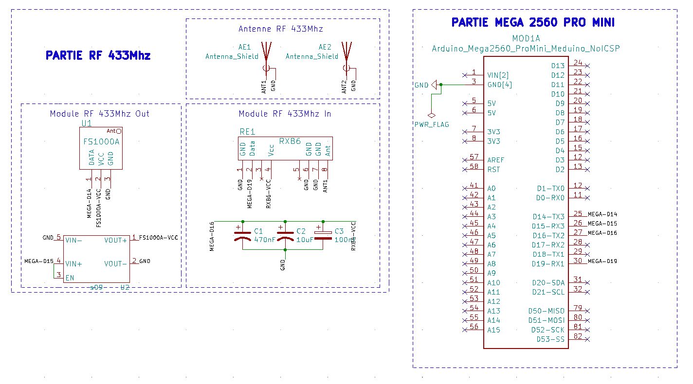
 rflink_schema.jpeg.
                                      I have an emission issue, the module RF 433Mhz Out not have 12v in VOUT+.
                                      What could I need to do.

                                      This is the pcb design, maybe it needs some improvement.
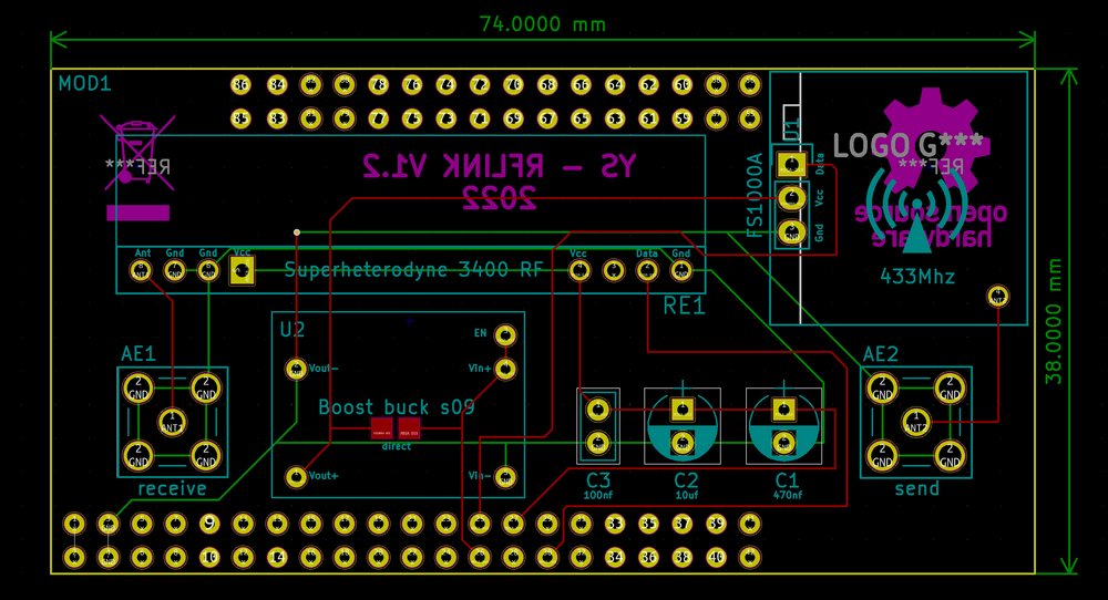
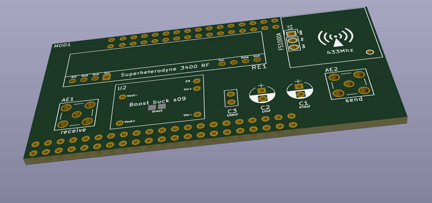
                                      mon_rflink_pcb_design.png

                                      mon_rflink_pcb.png

                                      Thanks

                                      1 Reply Last reply
                                      0
                                      Reply
                                      • Reply as topic
                                      Log in to reply
                                      • Oldest to Newest
                                      • Newest to Oldest
                                      • Most Votes


                                      13

                                      Online

                                      11.7k

                                      Users

                                      11.2k

                                      Topics

                                      113.1k

                                      Posts


                                      Copyright 2025 TBD   |   Forum Guidelines   |   Privacy Policy   |   Terms of Service
                                      • Login

                                      • Don't have an account? Register

                                      • Login or register to search.
                                      • First post
                                        Last post
                                      0
                                      • MySensors
                                      • OpenHardware.io
                                      • Categories
                                      • Recent
                                      • Tags
                                      • Popular