Air Quality Sensor


  • Admin

    @epierre said:

    MH-Z14

    Like this little puppy?


  • Hero Member

    @hek exact !


  • Hero Member

    @epierre said:

    @korttoma look above to S_CO2Sensor.json D_CO2Sensor.xml D_CO2Sensor.json, if you can test it...

    Thanks, found the device files and got the device included again.
    Seems like my MQ-2 is always reporting 0 or nothing at all. I guess I need to try to calibrate it again.
    It will do the calibration every time the sensor is restarted right?
    How can I calibrate the sensor if I put it somewhere where the air is not clean enough? (bring clean air in a jar? 😉 )

    Maybe it would be an idea to add a calibration button to the mix and when run using the button it would save the calibration related data in the RAM so it can then always use this calibrated value and then it would not re-calibrate every time it loses power.
    I have the 10k resistor between GND and A0, is this really necessary?
    Does the potentiometer on the sensor board affect the analog out at all or is it only for sensitivity on the digital out?

    Sorry for all the questions 😉


  • Hero Member

    @korttoma said:

    Thanks, found the device files and got the device included again.

    So you confirm they can be used as is ?

    @korttoma said:

    Seems like my MQ-2 is always reporting 0 or nothing at all. I guess I need to try to calibrate it again.
    It will do the calibration every time the sensor is restarted right?
    How can I calibrate the sensor if I put it somewhere where the air is not clean enough? (bring clean air in a jar? wink )

    this is the ongoing work, except CO2 which is known to be 399ppm (co2now.org) that should report this in clean air, for the other that should be little, and for deadly gases a full warning if this is high.

    @korttoma said:

    Maybe it would be an idea to add a calibration button to the mix and when run using the button it would save the calibration related data in the RAM so it can then always use this calibrated value and then it would not re-calibrate every time it loses power.

    That is an option, but EEPROM has a 100k write cycle only... this is what citizensensors says about it:

    1) Metal oxide gas sensors have intrinsic drift over time i.e. it is necessary to perform calibration on a regular basis.
    
    2) Because of spread in baseline resistance, sensitivity, cross-sensitivity, temperature dependency it is not possible to apply same calibration parameters to all the sensors.
    
    3) This type of sensor is efficient to detect change in concentration but not well adapted to absolute readings because of multiple dependency (T, RH, cross-contaminants).
    
    4) Using smart algorithm allows indicating useful information like the correlation with CO2 in confined space like offices or buildings (see VZ-87 in attachment).
    
    For absolute readings with high accuracy and repeatability I agree with you that you should use another technology.
    

    From this we have the calibration issue... in another post, since they only report resistance, they say they will rebuild all their platform to address callibration issue... but since calibration depends only from a reference gas concentration... only the pre-calibrated sensors remains viable for the low cost MQ/MICS/TGS will never be really calibrated...

    @korttoma said:

    I have the 10k resistor between GND and A0, is this really necessary?
    Does the potentiometer on the sensor board affect the analog out at all or is it only for sensitivity on the digital out?

    no you can remove it, I have observed a different behavior when moving it, it looks like it is shared by both digital and analogic for the same reason. What I'd like to find is where to measure the resistance for there are often some more on the board.

    @korttoma said:

    Sorry for all the questions

    good questions are always useful, especially when they meet my current subject of interrest 😉


  • Hero Member

    @epierre said:

    @korttoma said:

    Thanks, found the device files and got the device included again.
    So you confirm they can be used as is ?

    well, for the device in Vera I had to change the parameter "device_file" from "D_AirQuality1.xml" to "D_CO2Sensor.xml".
    I don't get any errors but I also do not get any values but I guess this is because my node is not sending any values.

    I'll try to look in to why my node is not reporting any value and try to remove the 10kR and see if I can measure the load resistance of my MQ-2 sensor board and maybe even remove some unnecessary components from it...


  • Hi All. Very interesting stuff, thanks all for sharing! I'm attempting to integrate an MQ-2, MQ-6 and MQ-135 (sensors only, no boards) using parts of epierre's sketch but I'm confused on a few things on how to set it up properly:

    1. What resistor(s) should go between A0 and ground? Keep in mind I'm not using a sensor board with built in protection resistor. Should there be a protection resistor then an adjustable pot for calibration?
    2. define RL_VALUE (5)
      -- does this refer to the size of the protection resistor between A0 and ground?
    3. define RO_CLEAN_AIR_FACTOR (9.83)
      -- does this value need to change at all?
    4. float Ro4 = 2.511;
      -- when you say this needs to be tuned to 10k, does that mean put a pot between A0 and ground and adjust until the calibration R0 is 10k?

    Sorry for all the questions, I appreciate any input! Thanks!


  • Hero Member

    @pbo

    1- see http://www.electronicaestudio.com/docs/SHT-114.pdf Fig 2 for wiring, the adjustable resistance is with ground and the sensor.

    2- yes

    3- Ro is calculated on first launch expecting you do this outside.
    Ro = MQCalibration(MQ_SENSOR_ANALOG_PIN);

    4- this is a default value I observed here. again the datasheet recommands for MQ135 20K to be in range with their values:
    we recommend that you calibrate the detector for 100ppm NH3 or 50ppm Alcohol concentration in air and use value of Load resistance that( RL) about 20 KΩ


  • @epierre

    Thanks for fast reply! I think i understand all but point #4... What do you mean by the Ro needs to be tuned to 10k? Using the adjustable resistor? Does that mean that the calibration number in fresh air at startup should ideally reach a set number, 10k?

    Since I don't have access to properly calibrate the sensor against a know quantity of gas, I thought the rough calibration would occur in clean air at start up, is that correct?

    Sorry for all the questions, it's a bit complicated. Thanks again!


  • Hero Member

    @pbo as stated above, the sensors evolve in their life... let's say that the value recommended by the datasheet is the best if you can.

    clean air calibration means that you should have a 0 value in clean air. Let's say that for CO2 the actual value is 399... so it should not be 0, but the clean air calibration is "assumed" quite good for LPG, SO2, NOx... that should be present in very little quantity, and again this is when the value increases a lot that it gets dangerous... there are some discussion on this above.


  • Hero Member

    I tried to analyze what is on the small ciscuitboar for my MQ-2 sensor an here is what I think it contains:
    upload-7d5906ec-43dc-4e10-a66f-65c84d5026cc

    So adding the 10K between AOUT and GND is pointless. So what now? Can I use it as is and just use the 1K value for RL in the sketch or is it recommended to change the 1K to something else (10K)??


  • Hero Member

    @Yveaux right, I opened a dispute with the seller, since I observed also no/nearly no answer to match burning with the sensor, he didn't even answer thus closing the dispute in my favor... that will be a good warning to me about those undocumented sensors comming from only one supplier without datasheet... there are other around, I shall avoid them..


  • Hero Member

    @korttoma You've been lucky finding such a schema, but it is strange there is a resistance on the other side of the sensor, and the variable one is not where expected... maybe the 1K is wrong on the schema, can you mesure it on the board?

    5.1 Ohm is low...

    The RL here is for the voltage comparator that gives the digital output with led.

    MQ-2 datasheet asks for Rs in 3KΩ-30KΩ
    If this is right, then the value that the autocalibration "in clean air" should give you something around 1K.

    The MQ-9 datasheet is a bit more versatile:
    Power of Sensitivity body(Ps): Ps=Vc^2×Rs/(Rs+RL)^2
    Resistance of sensor(Rs): Rs=(Vc/VRL-1)×RL

    MQ-9: Rs(in air)/Rs(100ppm CO)≥5

    I fear they are using a standard board for all sensors and that the resistance value may be wrong from this, just because they want to deliver a digital signal...


  • Hero Member

    @epierre

    I did not find the schema, I measured the board and figured it out myself so it might be wrong.

    Could you draw a schema that would show me exactly how it would preferably look so I can change it? Because I'm clearly not smart enough to understand it from your descriptions. Please explain it to me like I was 4 years old 😉


  • Hero Member

    Now changed my sensor according to this (disconnected the OP related to DOUT) :
    upload-94e081f9-006e-4d91-b736-3f82ef8e119b

    Please confirm that this is how it is preferred to be connected.


  • Hero Member

    Hello,

    I guess here you have the same that the datasheet, so I assume it is ok 😉

    I've been working to port sketches to a Spark Core with good results, the 12 bits ADC gives more precise values, at least the MQ135 is now very sensitive.

    I am also correcting errors in the sketches I have produced.


  • Hero Member

    Hello,

    A good article on the comparison of 3 same MQ-7 sensors

    A lot of good questions, not easy to answer! It is good you tryed it with three sensors instead of just one, and you can see there is a lot of variation from one sensor to the next of the same batch.
    [...]
    As to the value of Ro, that is the million dollar question. You have to have a known calibration source of CO in order to determine that! Each MQ-7 sensor will be different. The normal levels in a lab or home will be (should be!) well below the level that this sensor can detect and discriminate. It's lower limit implied in the data sheet is around 50ppm, which is where it begins to be dangerous for continuous exposure. Do read wiki and other sources about carbon monoxide and levels that can occur under different conditions.

  • Hero Member

    During the weekend I did the hardware changes and tried my MQ-2 sensor again and now if I hit it with smoke (I have smoke on a can) I do get values in Vera under the Variable1 property. No values on the dashboard device itself. I guess some changes are needed for the device file to display the V_VAR1 or we should use something else than V_VAR1.

    If you have already updated the sketch for the MQ-2 please let me know where I can get the latest version so I can try it out.

    btw, is the MQ-2 supposed to give the value 0 after it is calibrated in clean air? My sensor sends the value 0 all the time unless I hit it with my smoke can.


  • Hero Member

    @korttoma said:

    If you have already updated the sketch for the MQ-2 please let me know where I can get the latest version so I can try it out.

    btw, is the MQ-2 supposed to give the value 0 after it is calibrated in clean air? My sensor sends the value 0 all the time unless I hit it with my smoke can.

    Yes I am deeply modifying it, and will have a question for @hek : to have something consistant in time, it owuld be better to have the initial calibration stored, either in EEPROM or as a VAR on the server. Could it be possible that I introduce a loop that wait till the var is answered and if not go into calibration ?

    @korttoma the best sketch so far is the following, to be scaled down to one sensor, remove specific Mega initialization. I will make a simpler one based on this soon, as I have already done it for the Spark core.
    https://github.com/empierre/arduino/blob/master/MQv01dgi_1_4.ino


  • Admin

    @epierre

    The best solution (and most simple) is to keep calibration data in EEPROM.


  • Hero Member

    Now some questions I have currently:

    I've used your clean air calibration in open air given values of air concentration where appropriate. Around sept 20th I applied this method t omy sketches and I have since sensors that are very much more reactive ! Only 2SH12 has no curve, it is voltage for this (damn) sensor doesn't have a datasheet...

    I don't know if this was this predictible...

    They are all placed inside a room that I sometime open to clean air. Also there are restarts that calculates again those values where you see it drop maybe, but anyway it will still go to the previous values.

    MQ135 in CO2:
    MQ135-CO2.png
    MQ2 in Smoke:
    MQ2-Smoke.png
    2SH12 in SO2 in voltage:
    2SH12-SO2.png
    MQ6 in O3:
    MQ6-O3.png


  • Hero Member

    @korttoma I have found a sketch that may interrest you about the gas sensors boards:

    http://www.parallax.com/sites/default/files/downloads/27983-Gas-Sensor-Board-A-Schematic.pdf

    Their document speaks also about calibrating some gases:
    http://www.parallax.com/sites/default/files/downloads/27983-Gas-Sensor-Board-Guide-v1.0.pdf


  • Hero Member

    @Yveaux I have doubts about calculing the resistance, for it is depending on the steps, either 1024 or 4096, and/or the voltage either 5V or 3.3V.

    I started with this formulae:

    return ( ((float)RL_VALUE*(1023-raw_adc)/raw_adc));
    

    But saw Davide Gironi using this one:

    return  (long)((long)(1024*(long)RL_VALUE)/raw_adc-(long)RL_VALUE);
    

    RL_VALUE=22000


  • Hero Member

    @Yveaux @korttoma
    Bummer... this is the same formula when doing the reduction.... one is 1023 the other 1024 the only change.

    The RL_VALUE for Davide was 22k, when I mesure the resistance with Analog out with ground, I get 0,996 or 0,999 ohms depending on the sensor. I guess this is the RL_VALUE of the board which is way below the sensor maker recommendation (between 10K and 47K for a MQ135).

    Also, I saw that the pot on the board does not change the analog to ground resistance, meaning it is used only for comparison of the digital output....

    Am I correct in mesuring this ?


  • Mod

    @epierre said:

    Also, I saw that the pot on the board does not change the analog to ground resistance, meaning it is used only for comparison of the digital output....

    That seems to match the schematic above where the pot connects to + of the lm393


  • Hero Member

    @Yveaux Doing so, I have used a RL_VALUE for each board I mesured, one went to 5MOhms...

    MQ2:-8.85
    MQ6:0.00
    MQ131:0.00
    TGS2600:0.00
    MQ135:0.00
    2SH12:-155004.00
    TGZS2602:0.00
    

    Something to be noted: same boards have the same resistance, whatever the sensor maker recommendation, this is a pity...

    The output I have:

    MQ2    :LPG   :7ppm    CO    :0ppm    SMOKE :10ppm
    MQ6    :LPG   :0ppm    CH4   :0ppm
    MQ131  :CL2   :0ppm    O3    :0ppm
    TGS2600:H2    :0ppm    C2H5OH:0ppm C4H10 :0ppm
    MQ135  :CO2   :0ppm    CO    :0ppm     CH3   :0ppm    NH4    :0ppm
    2SH12  :SO2   :-154588.20 raw 
    TGS2602:C7H8  :0ppm
    Dust   :raw   : 0    Voltage: 0.00 - Dust Density: -0.10
    

    something to remember: MQ135 was calibrated for 1ppm of CO, not 399ppm of CO2, so the calculated value is very low, a per gas Ro must be calculated (clean air calibration) if several gas on one sensor is required to be displayed.


  • Hero Member

    Some interresting points from another discussion on the MQ138 that is given for HCHO.

    Historically a datasheet said so, but it is impossible to read the datasheet curves:
    http://china-total.com/Product/meter/gas-sensor/MQ138.pdf

    The latest ones do not speak of HCHO any more.

    An available alternative: grove is a wsp2110 and datasheet can be found.
    http://www.seeedstudio.com/wiki/Grove_-_HCHO_Sensor


  • Hello all,

    I'm new here, thanks to this topic very interesting for my personal project: a mobile air quality sensor.
    (sorry for my english, i'm french)

    Fistly, congrat's @epierre and the other, for having shared all this informations!
    (it's a litte funny because we had the same idea in the almost same time)
    So after having read the entire subject, here my questions (the number in front is the number post):

    _
    17 - @epierre, I haven't well understand How you can distinguish individual gas from a sensor who react with several gas.

    45 - The "Wunder Weather" list that you talked about, it's a website?

    55 - What David did you answer to you about "if he speaks of the organic sensor or the ceramic ones"?
    Moreover, what are the organic sensors? Have you example?

    72- On winsensor.com, an chinese gas sensor producer, the MQ-7 is more powerfull... I don't know who trust, maybe it's not the same?? See the PDF datasheet here.

    81 - Where did you read that the lastest one don't speak of HCHO anymore?
    After some research, I founded two, one who speak about HCHO here in english , and the other who don't....but I'm not sure (beacause in chinese) here.

    Otherwise, for the WSP2110 datasheet, it is here! But chinese too =/

    Regards,
    Alex.


  • Hero Member

    Hello,

    This is a short post, half has been lost in a forum crash, I hope the best remains 😉

    17 - @epierre, I haven't well understand How you can distinguish individual gas from a sensor who react with several gas.
    

    You cannot as I showed below with the broken perfume bottle, you can guess there is one, but not which one.

    45 - The "Wunder Weather" list that you talked about, it's a website?
    

    This is wunderground.com

    55 - What David did you answer to you about "if he speaks of the organic sensor or the ceramic ones"?
    Moreover, what are the organic sensors? Have you example?
    

    The organic are the one that have a lifetime of 2 years, calibrated but wery expensive (aroung $150+ apiece), the winseng one for example, big and round.

    72- On winsensor.com, an chinese gas sensor producer, the MQ-7 is more powerfull... I don't know who trust, maybe it's not the same?? See the PDF datasheet here.
    

    this is hard to say... the MQ-7 is quite special with a sequence to power it up, and readings every period.

    81 - Where did you read that the lastest one don't speak of HCHO anymore?
    After some research, I found two, one who speak about HCHO here in english , and the other who don't....but I'm not sure (beacause in chinese) here.
    

    I don't see mention of HCHO (formaldehyde) in the english one (n-Hexane, Benzene, NH3, alcohol, ,smoke, CO. I found one in chinese with the link above but the curve couldn't be exploited. Please remark that Alcohool has not a single formula, but here they show only one curve, not very precise.

    Otherwise, for the WSP2110 datasheet, it is here! But chinese too =/
    

    Yes for this one something can be done, but there is no for WSP1110 there is no...


  • Ok! Thanks.

    And what about the ceramic sensors (like MQ serie). How long can we trust them?


  • Hero Member

    @alex said:

    Ok! Thanks.
    And what about the ceramic sensors (like MQ serie). How long can we trust them?

    a bit longer but they vary in time as Davide made the remark, so calibration is not one time in its life...


  • Hello

    @epierre : after received the PPD42NS, compared to the DSM501A, which one is the best do you think?

    Other things, I planned to purchase soon the sensors that I need for my air station.
    You made a list on the #1 post, and it's very useful thanks, but now I have to choose between them for each gas targeted (maybe some sensors are still missing on the list below)

    Which one appears for you, the better for each gas, with a reasonable price?

    O3		    MQ131   MICS-2610    Mics-2614
    NO2 	      MiCS-2710    MiCS-2714
    NO            ? 
    PM10 PM2.5    PPD42NS    SamYoung DSM501
    Benzene	   MQ135			
    CO  	      MQ307A   MQ309A   AQ-7   MiCS-5525   TGS2442
    So2 	      MQ136
    COV       	MQ135  TGS2602
    CO2 	      MQ135

  • Hero Member

    @alex said:

    @epierre : after received the PPD42NS, compared to the DSM501A, which one is the best do you think?

    I currently have only the DSL501A working, many issues with the dead Shinyei (still in dispute escalade) and getting one from another seller takes so much time...

    Which one appears for you, the better for each gas, with a reasonable price?
    O3 MQ131 MICS-2610 Mics-2614
    NO2 MiCS-2710 MiCS-2714
    NO ?
    PM10 PM2.5 PPD42NS SamYoung DSM501
    Benzene MQ135
    CO MQ307A MQ309A AQ-7 MiCS-5525 TGS2442
    So2 MQ136
    COV MQ135 TGS2602
    CO2 MQ135

    The price is low, but so is the result. Only the CO-MH-Z14 is calibrated. For all the others, there is the calibration issue.

    See the sketch for a lit of known/tested sensors (some I don't have but a frien asked me for the curves so I added it to the Mega sketch)
    https://github.com/empierre/arduino/blob/master/AirQuality-Multiple_Gas_Sensor1_4.ino

    • The MiCS are problematic to find in Europe (!) so I have only one that I have not yet tested.
    • The Figaro have been tested, but it is hard to know how to really test them on some gases...
    • The MQxx:
      • MQ2: good result on smoke
      • MQ135 good result on CO2
        The others I'm not yet able to give any opinion.


  • Great project!
    I hooked up an MQ135 (sensor on a little pcb with (i think) smd resistor 102 (=1K ohm) between gnd and B )
    The readings are however all over the place (135ppm to 1332ppm), so i think i need to calibrate. The raw reading is alwas in the range 71-80 (inside).

    I know i have to get it outside and the reading should be 392 or 399 ppm but i am unsure what var i should change?
    The sketch says mq135_ro (this has to be tuned 10K Ohm) but that does not seem to be used in the calculations?

    I tried the sensor outside, but I am getting some different readings: the measured value changes from 59 to 82. The mq135_ro (i suppose that's the suggested ro) from 3081.00 to 81416 (does not go linear with the measured value?
    The sensor was heated for more than 24h and then moved outside (started measuring after 5min, in windy conditions)


  • I'm using the standard Smoke sketch from Mysensor library and it seem to be crashing MySensor plugin on Vera edge. Below is a snapshot of the problem. Any ideas?

    Screen Shot 2015-05-07 at 8.13.01 AM.png


  • Hero Member

    I take it that you are talking about the Air_Quality sketch right? The problem is that you do not have the device files for this kind of sensor in your Vera MySensor plugin. There is another thread that contains the files, I'll see if I can find it.

    Edit: Found the thread -> http://forum.mysensors.org/topic/661/assistance-needed-completing-gas-air-quality-sensor


  • @korttoma

    I'm going to try experiment tomorrow... Thank you!


  • @epierre thank you for sharing this code - your work is stellar. I'm working with a team of three other people to build a payload for a near space weather balloon launch in a couple of weeks.

    We're using the MQ131 Ozone Gas Sensor and your code has been quite useful to us. One question though, when our data logger reads the sensor we're getting a single number value. We're not exactly sure what that number means. Could you help explain what we're seeing? Are we getting a ppb number? ppm? Or something else altogether?


  • Hero Member

    @jroseastro hello, first of all the MQ series are not so precise as that, use it for a test run, but for serious purpose please consider something better and with calibration.

    Ozone is quite chalenging, if you go very high, since the MQ nead heating to work, it will drain fast your batteries.

    For any sensor always refer to the datasheet.

    MQ131 is given from 5 to 100 ppb (reason you get only a single value) if you use the provided calibration sheet. So the result is the one from the curve. We've had a discussion not yet settled with @hek about units and this is why I've not put it, but maybe I should uniformize everything in ppm since this is the most prevalent value used.

    Also the datasheet says you need 6V to heat it, so you cannot heat it from the arduino except with a step up (not that good) or an external power source (best) with a voltage regulator.


  • Hero Member

    I'm now testing the MICS-6814 (3 sensors in one) given for :
    Carbon monoxide CO 1 -1000ppm
    **Nitrogen dioxide NO2 0.05 –10ppm **
    Ethanol C2H5OH 10 –500ppm
    Hydrogen H2 1 –1000ppm
    Ammonia NH3 1 –500ppm
    Methane CH4 >1000ppm
    Propane C3H8 >1000ppm
    Iso-butane C4H10 >1000ppm

    Datasheet maionly speaks on CO, NO2 and NH3:
    http://www.seeedstudio.com/wiki/images/1/10/MiCS-6814_Datasheet.pdf

    Here is are scripts:
    http://www.seeedstudio.com/wiki/Grove_-_Multichannel_Gas_Sensor

    http://www.seeedstudio.com/wiki/images/1/10/MiCS-6814_Datasheet.pdf

    Some readings:

    The concentration of NH3 is 0.99 ppm
    The concentration of CO is 1.20 ppm
    The concentration of NO2 is 0.15 ppm
    The concentration of C3H8 is 1000.04 ppm
    The concentration of C4H10 is 999.98 ppm
    The concentration of CH4 is 2991.14 ppm
    The concentration of H2 is 1.09 ppm
    The concentration of C2H5OH is 1.40 ppm
    

    I guess I'll make a script soon...


  • I think MQ131 need 24 hours preheating time.Because of preheating time it will be costly. and for MiCS 6814 how do you calculate or measured other values of gases?? Because sensor's data sheet it hard to understand


  • Hero Member

    @bhavika said:

    I think MQ131 need 24 hours preheating time.Because of preheating time it will be costly.

    no MQ is expected to run on battery for they always need pre-heating before getting a value.

    and for MiCS 6814 how do you calculate or measured other values of gases?? Because sensor's data sheet it hard to understand

    So fat I only use the provided library. Sensors are said to be factory calibrated, maybe a reason they are so costly. I'm not running it constantly at this time, but I saw no change in the few time I ran it so I'm still expecting to see something.


  • @epierre Hi...it is ameasing your work 😄

    I am wondering about Mq-135. We have troubles with reading differents gases.
    From the datasheet we read the slopes
    Gas X" X0" "Rs/R0 "Rs/R0 pendiente (log y- log y0)/(log x-log x0)"
    Air 200 10 3.6 3.6 0.00000
    co 200 10 1.3 2.9 -0.26783
    nh4 200 10 0.79 2.7 -0.41024
    c02 200 10 0.8 2.4 -0.36673
    3/4/ 200 10 0.72 1.9 -0.32391
    1/4/ 200 10 0.64 1.5 -0.28432
    +- 200 10 0.59 1.4 -0.28845

    the data are in the next worksheet https://docs.google.com/spreadsheets/d/18Z6XyxwXVsWdMIk9vbUuCucaLJDdmR0QUFSTYG79ftw/edit?usp=sharing

    ¿may you share with us your code for this sensor in order to see your slopes and Rs/R0 values ?
    ¿do you know the meaning of the name of gases with 3/4 or 1/4 or +-

    thank you in advance


  • Hero Member

    @haro

    based on a datasheet, this one:
    https://drive.google.com/file/d/0B8OvrwVDp8fCcWpHSjZNVzB1TjQ/view

    I apply a power regression (tool: http://www.xuru.org/rt/PowR.as ) on the following points (I've not marked down values but theses are close match):

    0.8 200 
    1 100
    2.3 10
    

    Result: y = 103.6748512 x-2.81699418
    Residual Sum of Squares: rss = 45.01031346

     ¿do you know the meaning of the name of gases with 3/4 or 1/4 or +-
    

    looks like you had a chinese datasheet 😉 just remember those are correlated gases based on particle size for those captors, so it is not very accurate...

    You can find many more sensors hare : https://github.com/empierre/arduino/blob/master/AirQuality-Multiple_Gas_Sensor1_4.ino or simply in https://github.com/empierre/arduino/blob/master/


  • @epierre
    Hi, May be I do not explain my point correctly (or maybe I misundertood ), let me try again.
    We adopt a code, which is the next. The blue lines are the points (for each gas we need two points) that we need.
    https://docs.google.com/document/d/1CevnhBLL9uoyZ31kkrMn-SXeOF_4e9YFGmchj46pGPY/edit?usp=sharing

    Specifically we read from the datasheet the pairs of points for CO
    point1 (lg200 , lg1.3)
    Point2 (lg10, lg2.9)
    then, we construct the data format:{ x, y, slope};
    COCurve[3] = {1.0,0.462,-0.268};

    We are wondering about the pair of points for the others gases or the { x, y, slope} data for them, could you share them?.

    and the other hand, the name of gases with 3/4 or 1/4 or +- appears as well in your datasheet (figure 3)... do you know why?

    thank you so much


  • Hero Member

    I prefer the power regression than the curves.

    From your datapoints :
    1.3 200
    2.9 10

    I find:
    y = 532.6744764 x-3.73371402
    rss=0

    I don't remember where I found the datasheet with the chinese names that I translated through google.


  • @epierre Now I see your point of view and of course it is better way to reduce the error.

    in the other hand, I found the datasheet in chinese an then a friend translate it.
    the meaning of the name of gases is for 3/4 (Alcohol), 1/4 (Tolueno) or +- (acetona)

    Thank you so much.


  • Hi,

    I've started working with an MQ135 sensor, attached to a board like the disucssion you had from a year ago. I measured some of the resistances between the Aouts and the sensor pins and seems similar with the 1kohm resistance between AO and Gnd, and the pot not changing the output.

    I was wondering if anyone managed to calibrate their board using the AO of this board, and if so how? I can't seem to get a good resolution, as it has noise of at least in the 10's of ppm.

    I'm considering whether its simpler to by pass the board and its amplifier, and directly hook set up onto the sensor itself with the correct resistors.


  • Hero Member

    @Yuki-M said:

    Hi,

    I've started working with an MQ135 sensor, attached to a board like the disucssion you had from a year ago. I measured some of the resistances between the Aouts and the sensor pins and seems similar with the 1kohm resistance between AO and Gnd, and the pot not changing the output.

    I was wondering if anyone managed to calibrate their board using the AO of this board, and if so how? I can't seem to get a good resolution, as it has noise of at least in the 10's of ppm.

    I'm considering whether its simpler to by pass the board and its amplifier, and directly hook set up onto the sensor itself with the correct resistors.

    Calibration is not possible as it varies between the same sensors of this construction class. Check datasheet on minimal sensibility also on low and max values.

    Also without a gas concentration it is not possible to calibrate it. The best guess is that co2now.org gives you that outside (aka clean air) it is 399 for CO2, but that would be only for CO2 and not the other gases !


  • @epierre Thanks for a rapid response!
    Yes I've been trying to calibrate it assuming out door air is at 399ppm. I understand each one has variances but would like to know how you guys worked it out.
    I'm using
    ppm = 116.6020682 (Rs/Ro)^-2.769034857
    from davide's blog http://davidegironi.blogspot.ch/2014/01/cheap-co2-meter-using-mq135-sensor-with.html#.VinvWX4rIuU

    Since the board show RL, I took that to calculate Rs. This lets me calculate Ro, thus calibrate it.

    Not quite sure where I'm going wrong. I had it working 8 months ago, and came back to it and couldn't figure out how i had it working so well.. I was able to get pretty nice graphs and now its very unstable.

    I'm having a play around with it, you can see my current points here https://thingspeak.com/channels/31162


  • Hero Member

    @Yuki-M said:

    @epierre Thanks for a rapid response!
    Yes I've been trying to calibrate it assuming out door air is at 399ppm. I understand each one has variances but would like to know how you guys worked it out.
    I'm using
    ppm = 116.6020682 (Rs/Ro)^-2.769034857
    from davide's blog http://davidegironi.blogspot.ch/2014/01/cheap-co2-meter-using-mq135-sensor-with.html#.VinvWX4rIuU

    Since the board show RL, I took that to calculate Rs. This lets me calculate Ro, thus calibrate it.

    Not quite sure where I'm going wrong. I had it working 8 months ago, and came back to it and couldn't figure out how i had it working so well.. I was able to get pretty nice graphs and now its very unstable.

    would say: let it burn for 24/48 hours to leave it clean itself 😉


  • IN MiCS 2614 , sensitivity factor is defined by "Rs at 100 ppb of O3 divided by Rs at 50 ppb of O3". From where you measured Rs at 100 ppb or 50 ppb.???


  • Hero Member

    Adjusting my mq-135 sensor took several atempts as the CO2 value of the atmosphere is not a constant value of 399ppm.
    This value is measured in Hawaii ( see http://co2now.org/ ) and is probably significantly lower than at your home. In germany for example you should calibrate your sensor when the wind comes from west over the atlantic which brings fresh air along. See http://www.donnerwetter.de/deutschland/co2.htm

    Everytime my sensor passed values below 400 I adjusted the R0 value. In the end I modified the sketch to be able to send this R0 value from FHEM to the sensor to avoid recompiling the sketch everytime.
    See
    https://github.com/windkh/mysensors/tree/master/CO2Sensor/CO2sensor.ino Line 440ff
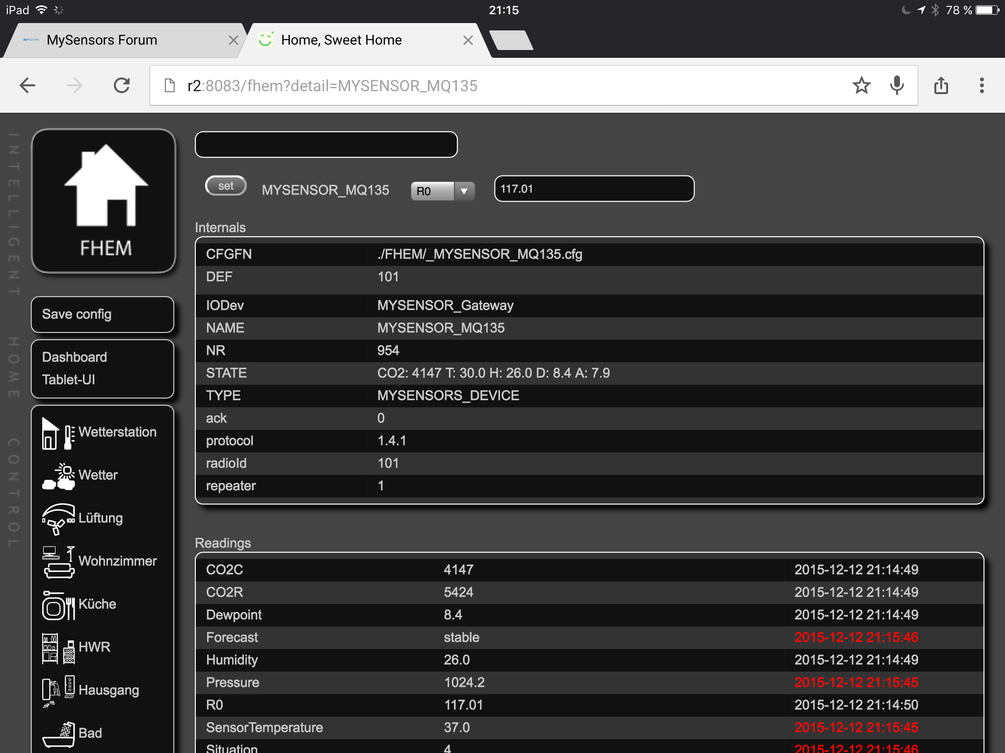
    image.png


  • Hero Member

    The sensor is in my kitchen. The value in the screenshot is very high as I made some french fries 2 hours ago.
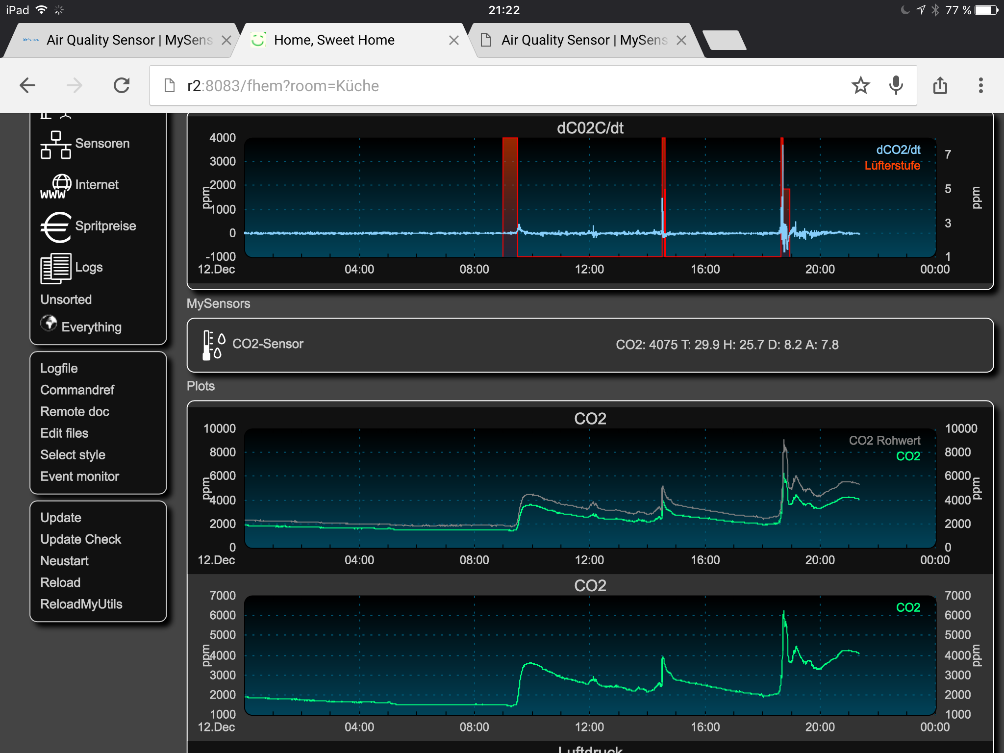
    image.png


  • Hero Member

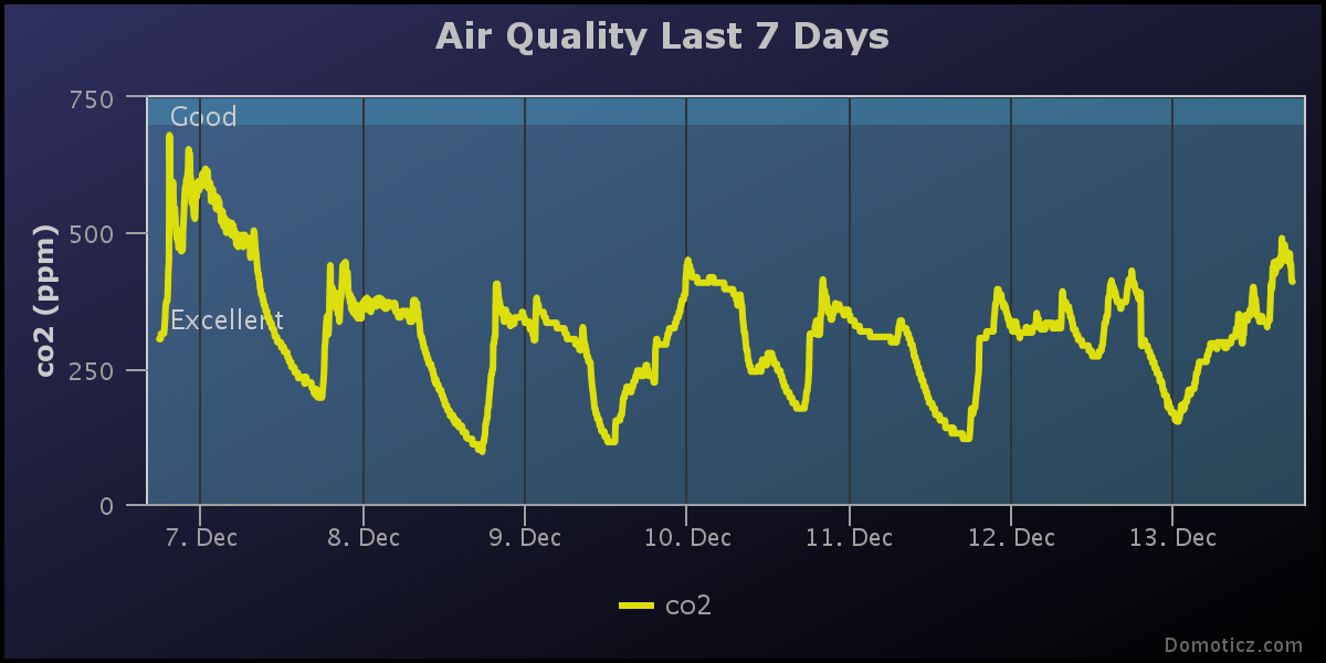
    @Heinz so bad I don't have a MQ135 running anymore to compare, here are the MH-Z14 curves I have near my desk.

    chart(6).png


  • Hero Member

    @bhavika said:

    IN MiCS 2614 , sensitivity factor is defined by "Rs at 100 ppb of O3 divided by Rs at 50 ppb of O3". From where you measured Rs at 100 ppb or 50 ppb.???

    this is just to tell you how much a double concentration scales up, here they just say it is somehow linear at ratio 2


  • @Heinz very nice work 👍 (wie heisst du im FHEM Forum?)

    Does someone have the values a MQ-07 needs to perform properly? I rally don't know how to gather the right values from the description.... 🙂

    Thank you


  • Hero Member

    @Rasenheizung if you base yourself on my template here https://github.com/empierre/arduino/blob/master/AirQuality-Multiple_Gas_Sensor1_4.ino

    H2
    1.3 50
    0.8 100
    0.28 400
    0.16 1000
    0.05 4000

    y = 73.59123879 x-1.355617483
    Residual Sum of Squares: rss = 87393.44418
    H2Curve[3] = {73.5912, -1.355617};

    CO
    1.6 50
    1 100
    0.39 400
    0.21 1000
    0.09 4000

    y = 99.27731641 x-1.513643469
    Residual Sum of Squares: rss = 43168.87424
    COCurve[3] = {99.27731, -1.51364};

    CO is a dangerous gas, the MQ7 is very sensitive to many things and no calibration too... for a serious work please think about using the MICS-6814 that is calibrated, includes 3 gases out of the box, and is very low consumption (can run on battery !)
    https://github.com/empierre/arduino/blob/master/AirQuality-CO-NO2-NH3.ino


  • What is the pre-heating time for TGS2442???


  • Hero Member

    @bhavika said:

    What is the pre-heating time for TGS2442???

    from datasheet: "the sensor’s resistance reaches to 90% of its final value in less than one minute"


  • So what is the conditioning period for testing in it??? It is two days.. What does it mean??


  • Hero Member

    @bhavika said:

    So what is the conditioning period for testing in it??? It is two days.. What does it mean??

    on this kind maybe to have it powered for a full two days to burn out the production "dusts" that may remain in.

    those sensors are not good science, see the correlation of gases they are reported for in the datasheet


  • Hero Member


  • I have a question for the MQ135. Do not always be above 500 ppm, the measured values? I also get values of 0. I suspect that it is due to the conversion. The values vary greatly. Is that normal? I get the values with an ordinary power supply. mq135 werte.PNG


  • This post is deleted!

  • Hero Member

    Looks strange, could you supply your code?
    Btw the sensor draws a lot of current, the power supply should be able to deliver 1A. Did you burn in the sensor for 12-24 hours?


  • I have used the code from epiere. Baking I have not done. I use different power supplies (USB, Samsung and a large controllable power supply). I sometimes feel that contacts do not function properly. But the sensor draws but only about 100 mA = 0.1 A? Then it seems to be on branding. I have three new sensors. Mostly we read that it is only an attempt here is to measure the CO2 content. When I check the values with a measuring instrument with which agree the details here https://olimex.wordpress.com/2015/05/26/experimenting-with-gas-sensors-and-arduino/ Branding should work outdoors? Can you show me a chart or values?


  • This post is deleted!

  • Hero Member

    I used this library:
    https://github.com/GeorgK/MQ135

    Together with this description:
    https://hackaday.io/project/3475-sniffing-trinket/log/12363-mq135-arduino-library

    Simple to use and very good explanations.


  • I've read about. It sounds interesting.

    I stand a little hard with the development. Is there a skit for MQ135.h and MYSENSORS?

    I will test this afternoon.


  • Hero Member

    Hi @paqor,
    I wrote a little sketch which you could use as a start, it uses the MQ135 library.
    I also used a timer library, but this could be replaced by a simple sleep, too.

    RZERO should be changed when calibrating the sensor, this can be done at compile-time or during runtime by sending the value to the sensor via the gateway.

    Unfortunately I could not test the sketch yet, but it should help you getting started.
    If you have a second sensor which provides humidity and temperature then you can also get the corrected ppm from the library,...

    good luck!

    /*
    MQ135 MySensor
    A0      white
    D0      black
    GND     brown
    5V      red
    */
    
    #include <SPI.h>
    #include <MySensor.h>
    #include <MQ135.h>
    #include "Timer.h"
    
    Timer timer;
    
    // 30 seconds
    #define TEMP_UPDATE_INTERVAL 30000
    
    // MQ135
    #define CHILD_ID_CO2 0
    #define CHILD_ID_R0 1
    
    #define CO2_SENSOR_ANALOG_PIN 0
    
    /// Calibration resistance at atmospheric CO2 level
    #define RZERO 300.0
    #define EEPROM_R0 0
    
    MQ135 gasSensor = MQ135(CO2_SENSOR_ANALOG_PIN, RZERO);
    int lastC02;
    float lastR0;
    
    //-----------------------------------------------------------------------------
    // MySensor
    MySensor gw;
    MyMessage msgCO2(CHILD_ID_CO2, V_VAR1);
    MyMessage msgR0(CHILD_ID_R0, V_VAR1);
    
    //-----------------------------------------------------------------------------
    void setup()
    {
        gw.begin(incomingMessage, AUTO, true);
        gw.sendSketchInfo("MQ135 Sensor", "1.0");
        gw.present(CHILD_ID_CO2, S_AIR_QUALITY);
        gw.present(CHILD_ID_R0, S_CUSTOM);
        
        uint8_t R02 = gw.loadState(EEPROM_R0);
    
        // get R0 from EEPROM
        float R0 = R02 * 2;
    
    	// do a plausibility check
        if (R0 > 1.0 && R0 < 400.0) 
        {
            Serial.print(F("Setting R0 from EEPROM: "));
        }
        else
        {
            Serial.print(F("Setting default R0: "));
            R0 = RZERO;
        }
    
        Serial.print(R0);
        Serial.println(F(""));
    
        gasSensor.setR0(R0);
        
        timer.every(TEMP_UPDATE_INTERVAL, timerHandler);
    }
    
    
    bool MQ135Changed()
    {
        bool changed = false;
    
        lastR0 = gasSensor.getRZero();
        Serial.print(F("R0: "));
        Serial.println(lastR0);
    
        {
            float ppm = gasSensor.getPPM();
    
            Serial.print(F("CO2 ppm: "));
            Serial.print(ppm);
    
    
            int roundedPpm = (int)ppm;
            Serial.print(F(" --> "));
            Serial.println(roundedPpm);
    
            if (roundedPpm != lastC02)
            {
                lastC02 = roundedPpm;
                changed = true;
            }
        }
    
        return changed;
    }
    
    
    void timerHandler()
    {
        bool airQualityChanged = MQ135Changed();
        if (airQualityChanged)
        {
            gw.send(msgCO2.set(lastC02));
            gw.send(msgR0.set(lastR0, 2));
        }
    }
    
    
    void loop()
    {
        gw.process();
        timer.update();
    }
    
    
    // Gets the R0 value from the gw passes ot to the lib and stores it into the EEPROM.
    void incomingMessage(const MyMessage& message)
    {
        Serial.println(F("Incoming Message:"));
    
        if (message.isAck())
        {
            Serial.println(F("This is an ack from gateway"));
        }
    
        uint8_t sensor = message.sensor;
        if (sensor == CHILD_ID_R0)
        {
            float R0 = message.getFloat();
    
            Serial.print(F("Incoming R0: "));
            Serial.print(R0);
            Serial.println(F(""));
    
            gw.saveState(EEPROM_R0, (uint8_t)(R0/2));
            gasSensor.setR0(R0);
            gw.send(msgR0.set(R0, 2));
        }
    }


  • I have compiled from various sources themselves something. The result is https://gleisnetze.de/2015/12/25/das-erste-kleine-programm/ described herein. The most plausible values I received with the MQ135.h library. For that I have then added the transfer after MySensors / FHEM.

    Bildschirmfoto vom 2015-12-25 07-53-25.png


  • Hello

    In MiCS 2614 or in any gas sensor. what should be the value of R0... Because in datasheet they mentioned that value is measured in ambient condition. Any default value for that??


  • Hero Member

    @bhavika said:

    Hello

    In MiCS 2614 or in any gas sensor. what should be the value of R0... Because in datasheet they mentioned that value is measured in ambient condition. Any default value for that??

    The datasheed propose the "clean air calibration": "Sensing resistance in air R0 is measured under controlled ambient conditions, i.e. synthetic air at 23 ±5°C and 50 ± 10% RH. Sampling test."
    so you should go outside and mesure the defautl R0 value in your environment.


  • Hero Member

    MQ-135 with 10k results in a R0 of around 360 in my environment. So you could start experimenting with values around 300-500. I had to use a voltage regulator to get reliable values from the sensor.


  • Hero Member

    a little update on the MICS-6814:
    NO2: sensible
    CO: flat
    NH3 flat
    chartNO2.jpeg

    For the HCHO:
    charthcho.jpeg

    sorry for the flat part, some arduino issues at this time


  • Mod

    Welcome @betthorn, great to have you here.


  • Hero Member

    I have had some questions about converting from mg/m3 to ppm gases, here are the weight values and a proposed method:
    NH3 17.03 g/mol
    CO2 44.01
    CO 28.01
    H2S 34.08
    NO2 46.01
    NO 30.01
    O3 48.00
    C6H6 78.11
    C7H8 92.14

    you have:
    NO2 50 μg/m3 gives 26,5868821 ppm
    O3 27 μg/m3 = 0.027 mg/m3 -> (8,31441298,15)/(48101,325)*27=13,7617025 ppm

    correct me if I'm wrong


  • Hero Member

    2016 is where IoT for gas sensors are moving to more maturity, Cooking Hacks / Libellium proposed so far Fibaro sensors, but are now proposing more pricey one that are calibrated.

    See https://www.cooking-hacks.com/shop/sensors/gas


  • Hero Member

    CO2 with MH-Z14
    0_1455112054292_chart(7).png
    NO2 MICS-6814
    0_1455112065552_chart(8).png
    HCHO sensor
    0_1455112071878_chart(9).png


  • In MQ135 sensor's datasheet , which line on the curve is used to find out the concentration of benzene?


  • Hero Member

    @bhavika said:

    In MQ135 sensor's datasheet , which line on the curve is used to find out the concentration of benzene?

    MQ135 is sensitive to particle size, benzene is one of these. I rememer someone who used the chinese datasheet and found a chinese to translate it.


  • @epierre I am testing a stripped-down version of your code from your AirQuality-MQ135.ino. I stripped it to make it run just stand-alone.
    What I don't understand is how to do the calibration. When I run it in outside environment (with 10k resistor), I get these values:

    valr 223
    Vrl / Rs / ratio:13387 / 20875.00 / 0.00
    

    What would be the next step for calibration?


  • Hero Member

    @supersjimmie replace MQ135_DEFAULTRO by your value 20875 in the sketch


  • @epierre Thanks, I thought it would be something like that, but that didn't work.
    I then got

    valr 242
    Vrl / Rs / ratio:5464 / 8520.00 / 0.00
    

    Nothing like around 400ppm.


  • Hero Member

    yes for the code must be updated, the value is the CO2 (or something else) detected above the 399 in atmosphere

      gw.send(msg.set(MQ135_DEFAULTPPM+(int)ceil(valAIQ)));


  • Thanks, but when calibrating something strange happens when I put the module outside:

    valr 270
    Vrl   / Rs       / ratio  / ppm
    61355 / 95673.00 / 0.00 / 399.00
    valr 265
    Vrl   / Rs       / ratio  / ppm
    62928 / 98126.00 / 0.00 / 399.00
    valr 260
    Vrl   / Rs       / ratio  / ppm
    64561 / 100673.00 / 0.00 / 399.00
    valr 256
    Vrl   / Rs       / ratio  / ppm
    378 / 589.00 / 0.00 / 399.00
    valr 252
    Vrl   / Rs       / ratio  / ppm
    1773 / 2764.00 / 0.00 / 399.00
    

    As you can see, the valr decreases slowly, but suddenly Vlr and Rs jump over.
    Vlr is the value of 'val', which is: uint16_t val = ((float)22000*(1023-valr)/valr);
    uint16_t is 16bit, so max 65535. It looks like my environment needs more than that?
    (in fact, your code defines the defaultro as 68550, which is also too much for a uint16?)


  • Hero Member

    @supersjimmie said:

    Vlr is the value of 'val', which is: uint16_t val = ((float)22000*(1023-valr)/valr);

    yes and this is why I did rewrite it to https://github.com/empierre/arduino/blob/master/AirQuality-Multiple_Gas_Sensor1_4.ino but did not updated this one...


  • @epierre I striped-down that AirQuality-Multiple_Gas_Sensor1_4.ino to use only MQ135.
    When used inside, the analogRead is 473, so a reasonble value.
    But the MQCalibration function returns 0. Which means the MQResistanceCalculation also returns 0.

    MQResistenceCalculation only does one calc:
    return (long)((long)(1024 * 1000 * (long)rl_value)/raw_adc-(long)rl_value);
    rl_value = float RL4 = 0.990
    raw_adc = 473 (measured as said above)
    (1024 * 1000 * 0.990) / 473 - 0.990 = 2142.266
    I checked that raw_adc is filled with the correct value (to be sure it is not lost somewhere).

    What looks to fix this, I changed everything to float . So:
    return (float)((float)(1024 .* 1000. * (float)rl_value)/raw_adc-(float)rl_value);
    Which can be simplyfied as:
    return ((1024 * 1000*rl_value)/raw_adc-rl_value);
    I went to float, because the function is created as float MQResistenceCalculation.

    This now gives some ppm values that are within a reasonable range (about 2000 here).

    Now I have to figure out how to do calibration on this method again...


  • Hero Member

    looks like I have to rework something... but not in the todo list right now... Imperihome is now back on top, and Particle on lipo/solar also...


  • Hello,
    I don't know how to calculate 3 numbers of LPGCurve[]. Can you explain clearly for me? Thank you so much !!!

    0_1456336543192_Capture.PNG


  • Hero Member

    @tantt2810 as explained above, if the datasheet has a logarithmic scale, you can use the power regression to approximate the curve. One tool for example to do this calculus:http://www.xuru.org/rt/powr.asp

    for a sensor discussed above I read this on the datasheet:
    H2
    1.3 50
    0.8 100
    0.28 400
    0.16 1000
    0.05 4000

    The xuru website gives me this:

    y = 73.59123879 x-1.355617483
    Residual Sum of Squares: rss = 87393.44418

    and thus I have::
    H2Curve[3] = {73.5912, -1.355617};


  • @epierre Thank you so much !!!
    Have a nice day =)) !!!


  • @epierre

    hi

    i am new here.

    sorry i am a little confused by with these new formulate.

    is it the key for module?


  • Hello,
    I'm don't understand the recipe below. Why RL_Value(Load Resistance)(1023-raw_adc)/raw_adc)? Can you explain for me?
    Thank you so much !!!
    /
    ***************** MQResistanceCalculation ****************************************
    Input: raw_adc - raw value read from adc, which represents the voltage
    Output: the calculated sensor resistance
    Remarks: The sensor and the load resistor forms a voltage divider. Given the voltage
    across the load resistor and its resistance, the resistance of the sensor
    could be derived.
    ***********************************************************************************/
    float MQ2::MQResistanceCalculation(int raw_adc)
    {
    return ( ((float)RL_VALUE
    (1023-raw_adc)/raw_adc));
    }


  • Hero Member

    @jenbaker said:

    sorry i am a little confused by with these new formulate.

    is it the key for module?

    if you have a module the datasheet gives you the values, yes. Remember this is their """""generic"""" calibration, in fact they all copy the other so don't expect your MQ** would follow this by the letter...


  • Hero Member

    @tantt2810 said:

    Hello,
    I'm don't understand the recipe below. Why RL_Value(Load Resistance)(1023-raw_adc)/raw_adc)? Can you explain for me?
    Thank you so much !!!
    Input: raw_adc - raw value read from adc, which represents the voltage
    Output: the calculated sensor resistance
    Remarks: The sensor and the load resistor forms a voltage divider. Given the voltage
    across the load resistor and its resistance, the resistance of the sensor
    could be derived.
    float MQ2::MQResistanceCalculation(int raw_adc)
    RL_VALUE
    (1023-raw_adc)/raw_adc));

    in fact it is above described, you have a voltage, you want a resistance.
    https://learn.sparkfun.com/tutorials/voltage-dividers

    datasheet needs a value which is the Rs/Ro (called here RL) where
    Ro: sensor resistance at 100ppm of NH3 in the clean air.
    Rs:sensor resistance at various concentrations of gases

    here the formula is a simplification of this:

    float Vrl = val * ( 5.00 / 1024.0 ); // V
    float Rs = 20000 * ( 5.00 - Vrl) / Vrl ; // Ohm
    int ratio = Rs/Ro;
    ppm = 37143 * pow (ratio, -3.178);


  • @epierre Hi you,
    I think the Rs/Ro is not RL. In the datasheet RL=5kOhm. As I know it is a resistance on board Arduino, and we set it 5kOhm. Is it right? I also don't know why we set it equal 5kOhm. =))
    And why 20000 is in "float Rs = 20000 * ( 5.00 - Vrl) / Vrl ; // Ohm" ?
    Please help me clearly. Thank you so much !!!


  • Hello,
    I have read the sensitivity characteristics curve in datasheet of MQ135 and I don't know AL R, 3/4, 1/4* and +- mean? Can you help me, please !!!
    NH4 represent for NH3, doesn't it ?
    Thank you so much !!!


  • Hi everyone,
    I have an CO2 MG811 sensor. I don't know where tcm pin connect with ?
    Please help me. Thank you so much !!!!
    0_1457101257425_F08406-CO2-Carbon-Dioxide-Sensor-Module-font-b-MG811-b-font-Voltage-0-2V-Voltage-Output.jpg


  • Hello, I'm working with an MQ-136 sensor, and am interested in measuring H2S and/or SO2 concentrations. I've got a simple sketch written which gives me a fairly consistent value on the serial monitor, but I've tried to run the multiple gas sensor sketch both complete and I also tried picking apart the sketch just to include MQ-136 related variables and algorithms, but I can't get it to work. It's showing too many errors to list here. Does anyone have simple conversions from the serial outputs to usable values for various gases that this sensor can measure?


Suggested Topics

57
Online

11.4k
Users

11.1k
Topics

112.7k
Posts