110v-230v AC to Mysensors PCB board
-
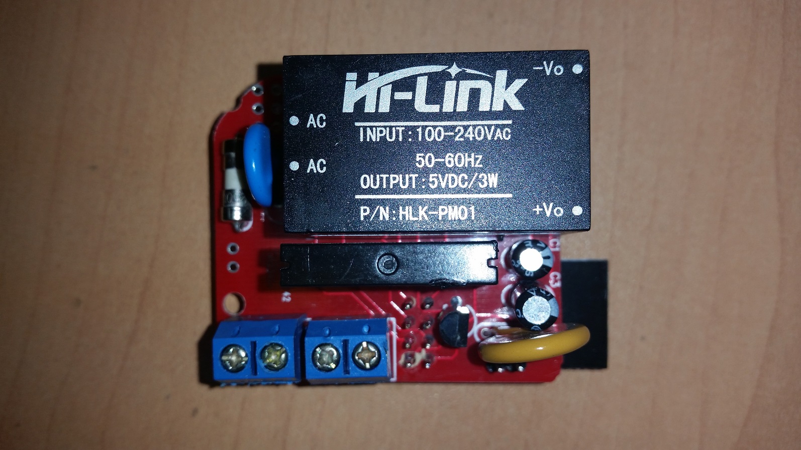
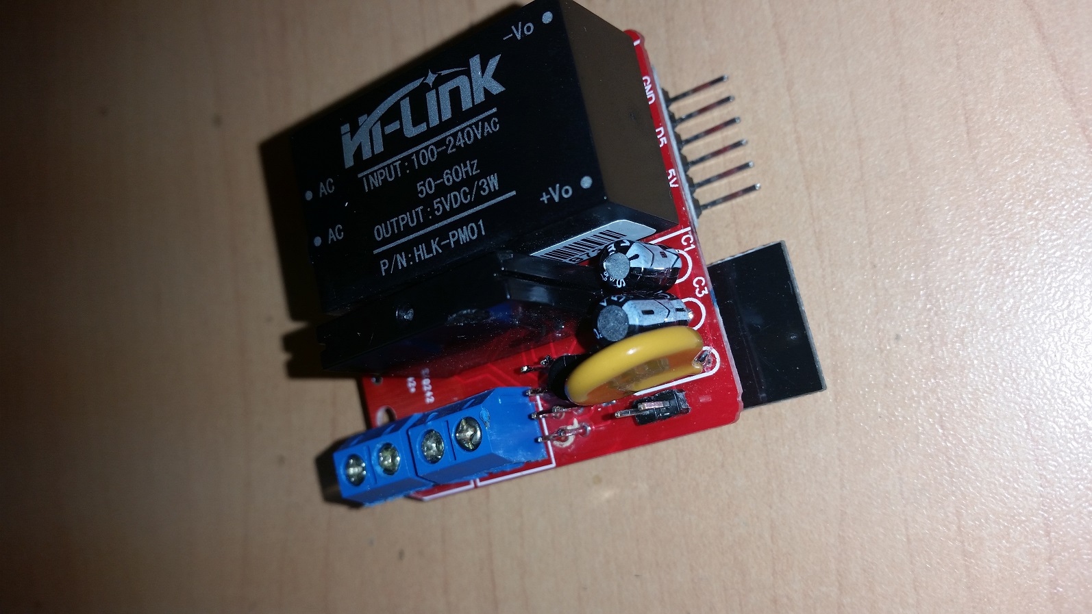
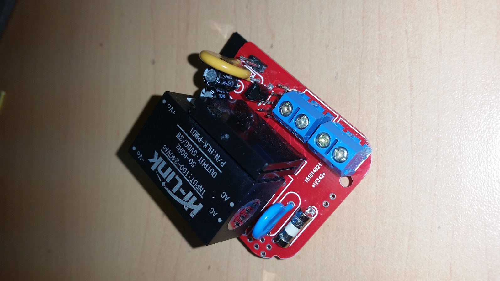
For those who wanted to see some pictures of the board:
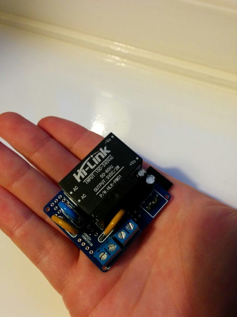
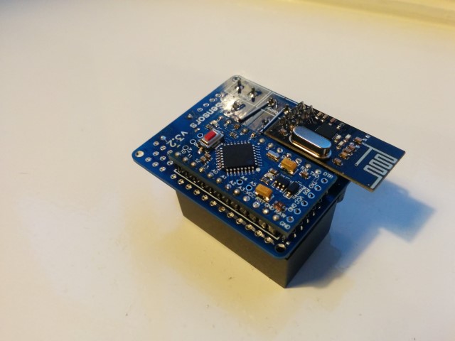
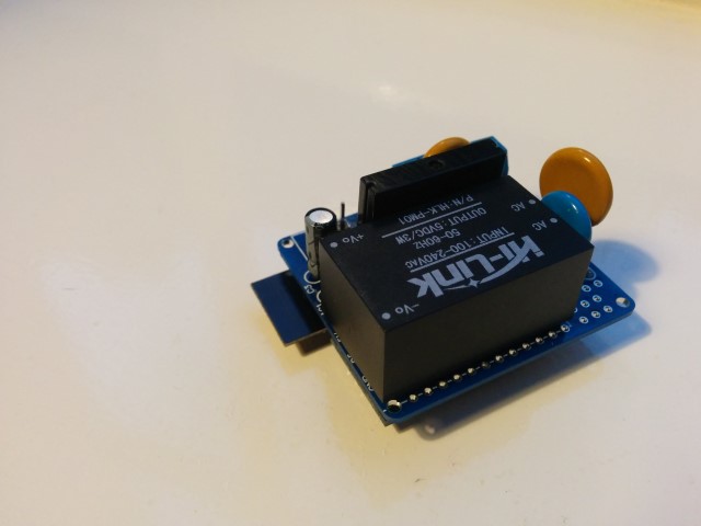
Small notice: These pictures are of a slightly older design. The newer design has a few minor changes like better component placement and a permanent fuse instead of this resettable fuse. But these pictures should at least give you an idea on how everything looks like, and shows how really small it actually is.
Also, I reinforced the traces of the 230v lines, which I absolutely recommend to do! (Although I do recommend to do it slightly more professional than I did on this prototype :))@aproxx said:
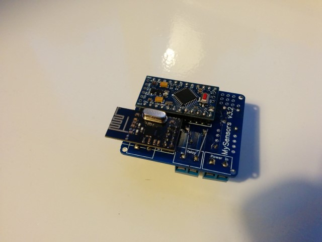
For those who wanted to see some pictures of the board:
Small notice: These pictures are of a slightly older design. The newer design has a few minor changes like better component placement and a permanent fuse instead of this resettable fuse. But these pictures should at least give you an idea on how everything looks like, and shows how really small it actually is.
Also, I reinforced the traces of the 230v lines, which I absolutely recommend to do! (Although I do recommend to do it slightly more professional than I did on this prototype :))I really like this design, but it would be even nicer when this fits a ESP8266 :) Maybe the PCB could be even smaller . And it works together with link text .
So is there maybe one of the PCB designer guys who can build /draw / design this 230v to ESP8266 PCB ? -
WOW, REALLY GREAT JOB!
-
Hello everyone,
This is a gr8 project, i am looking forward to make few sensor for my home. As i don't have any experience with electronics and very new to all these terms and components.
I would request anyone of you to, kindly post some pictures of the board with components in place that i can copy and make my boards.
**Specially 3 pin regulator and Capacitors **My first assembled board is not working, it looks like m doing something wrong with either the capacitors or the regulator. I checked my NRF24l01 VCC pin and not getting any voltage at all.
Please help me guys......
Thanks and Regards
Brij -
Hello everyone,
This is a gr8 project, i am looking forward to make few sensor for my home. As i don't have any experience with electronics and very new to all these terms and components.
I would request anyone of you to, kindly post some pictures of the board with components in place that i can copy and make my boards.
**Specially 3 pin regulator and Capacitors **My first assembled board is not working, it looks like m doing something wrong with either the capacitors or the regulator. I checked my NRF24l01 VCC pin and not getting any voltage at all.
Please help me guys......
Thanks and Regards
Brij@Brijesh-Mishra said:
I would request anyone of you to, kindly post some pictures of the board with components in place that i can copy and make my boards.
@the-cosmic-gate has already posted images above.
Perhaps you should post a picture of what you've done?
-
Thanks a lot for your response, this is what i have done so far.
-
Could I ask to the smart PCB builder's / designers to make the same 230v PCB but not using an Arduino but one of the ESP8266 versions , the the board could be even smaller and easier to fix in the wholes
-
Could I ask to the smart PCB builder's / designers to make the same 230v PCB but not using an Arduino but one of the ESP8266 versions , the the board could be even smaller and easier to fix in the wholes
@the-cosmic-gate, greetings to you. Kindly let me know, is there any issue with the component placement in the board. Not sure why it's not working :(.
Thanks
Brijesh -
@aproxx Great job. Just started to work with mysensors and I was looking for a power supply alternative to mobile phone chargers. Though one question; the board that you included the relay was really interesting. Why did you not proceed on this? Also, do you sell the PCB's?
-
@the-cosmic-gate, greetings to you. Kindly let me know, is there any issue with the component placement in the board. Not sure why it's not working :(.
Thanks
Brijesh@Brijesh-Mishra said:
@the-cosmic-gate, greetings to you. Kindly let me know, is there any issue with the component placement in the board. Not sure why it's not working :(.
Thanks
Brijesh
There absolutely nothing wrong, but I want to use the ESP8266 to build in instead of the arduino and 2.4 ghz radio (the ESP8266 is an Arduino incl WiFi) so the PCB can be much smaller I think.
-
@Brijesh-Mishra , I see two issues with your photos. 1) the 3.3V regulator is on backwards. If you earlier in this thread someone comments that the regulator needs to be put on backward. The white design on the board is not correct. That was also my experience with the boards I built. The flat side of the regulator should face the two cap's. 2) more importantly, it appears that you used a thermal fuse in the spot where fuse #1 goes. Fuse #1 is supposed to be a 300ma slo blow fuse. If that is what you have there no problem, but it looks like the thermal discussed in the thread. This board does not have a place for the thermal fuse. I would consider this a serious safety issue, but I am not an expert. Hope this helps.
@novicit, Thanks a lot for your help. i will make a new board as per your guidance and share the photos soon.
Regards
Brijesh -
-
Hi,
I now received PCBs from DirtyPCB. I'm searching components (but not from China sellers).
Can I use this varistor on the AC side?: http://uk.farnell.com/multicomp/mcsr391k10ds/varistor-60j-250vrms/dp/1856880
And on the DC side?: http://uk.farnell.com/multicomp/mcvz1206m050agt/varistor-multilayer-4vac-0402/dp/2462756Thanks in advance!
-
Hi all,
**UPDATE April 17 2016 **
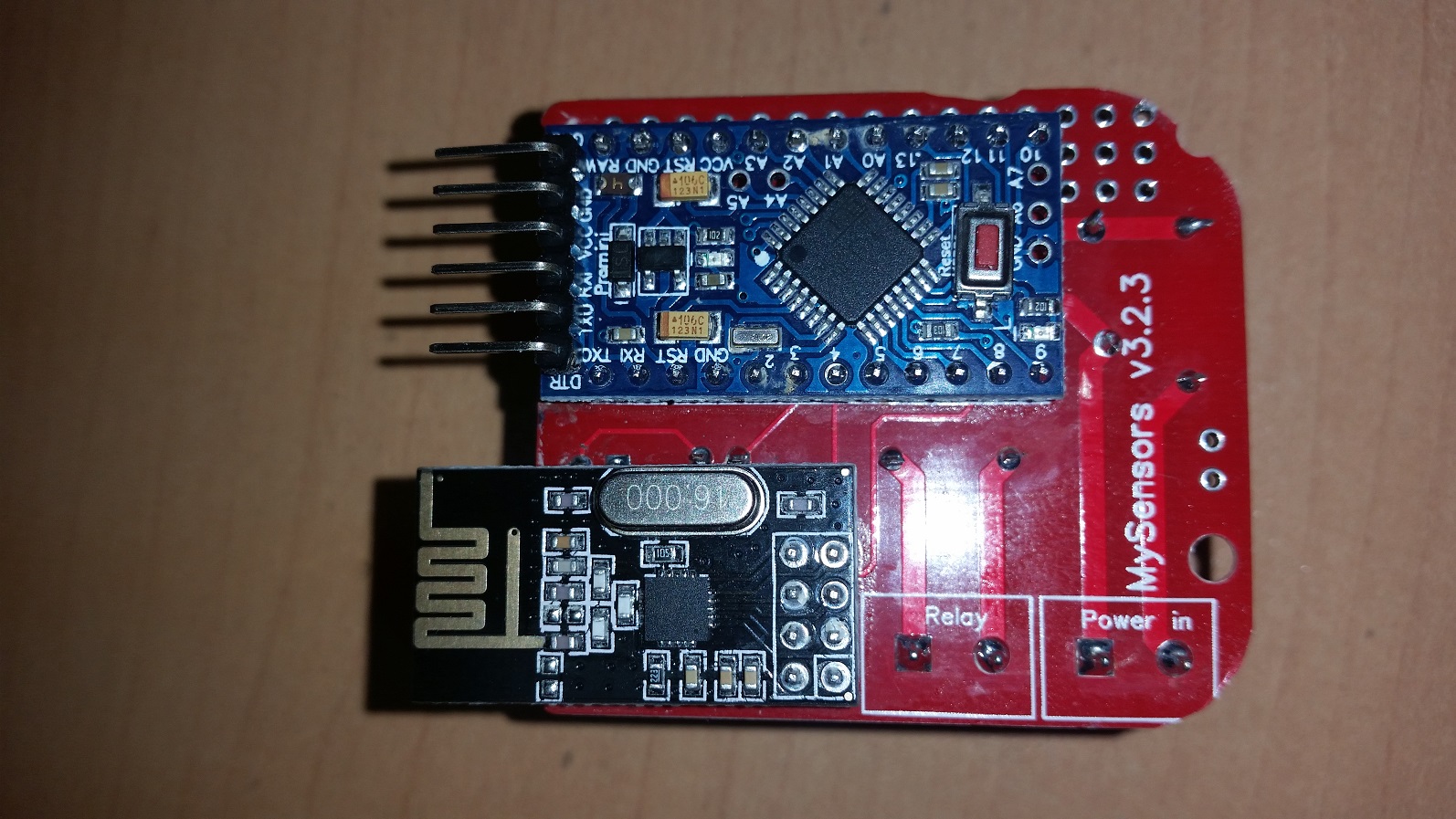
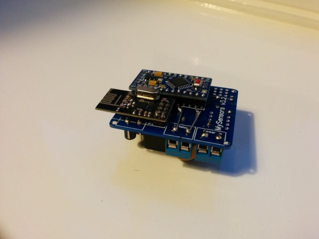
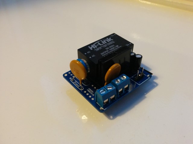
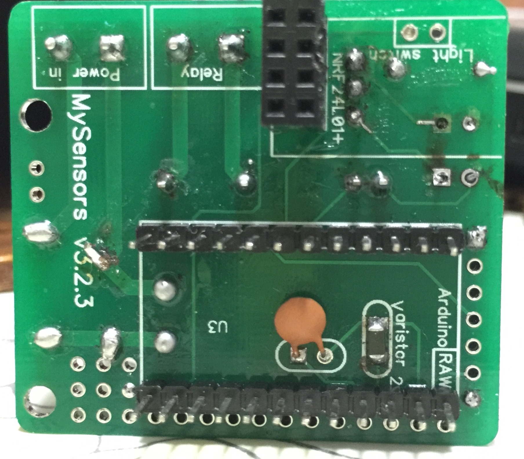
The latest version of this board is available HERE.After spending a few months on this forum and a few prototypes later, I decided I wanted to build a small but cheap PCB which could be placed in either the wall behind the light switch, or above the lamp.
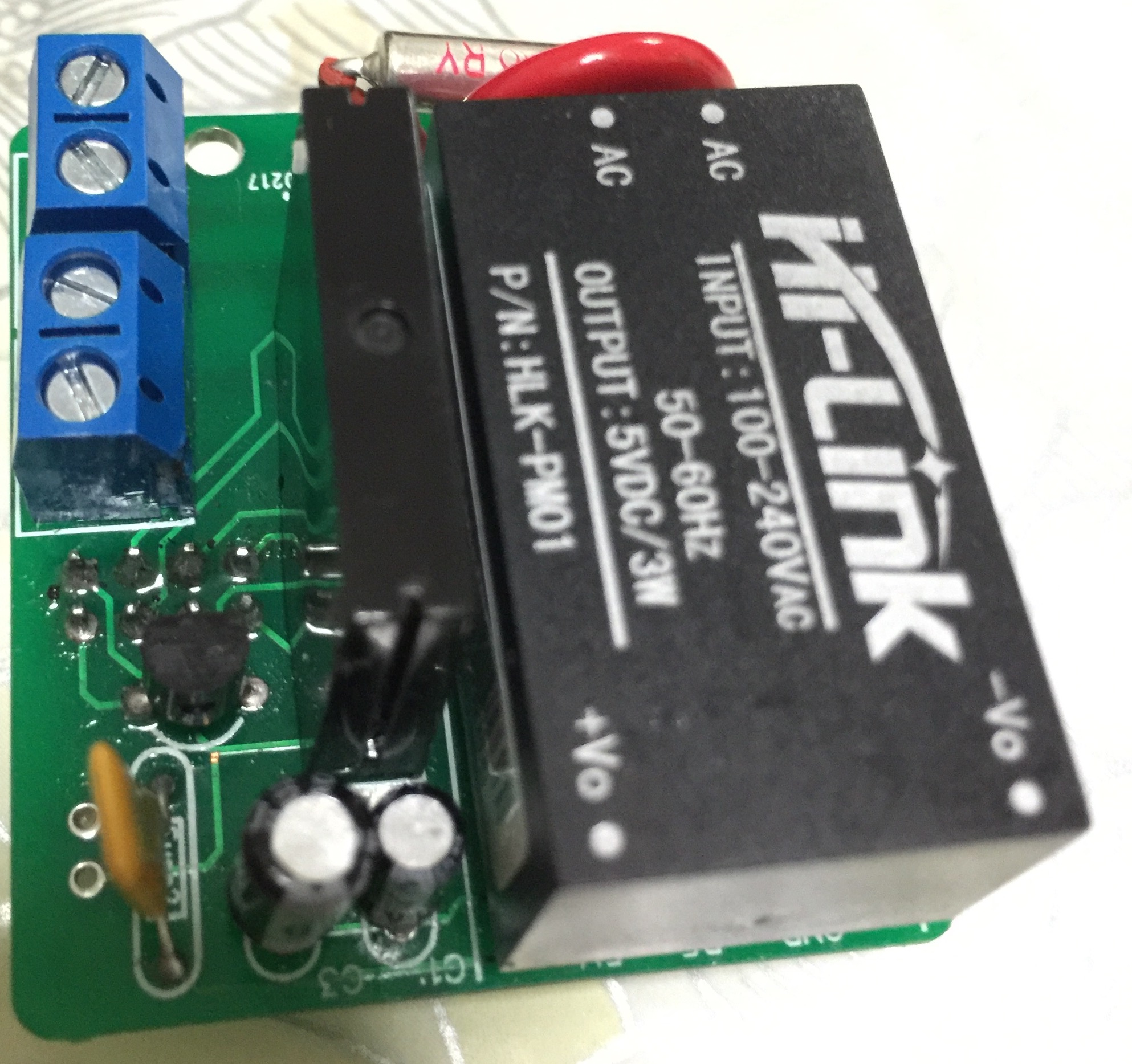
Besides the boards I've seen on this forum, I wanted these boards to contain a module to go from 230v AC to 5/3.3v DC in order to power an Arduino nano and the NRF module. I eventually ended up with a PCB which is about 4 by 4.5cm. So with all components attached I'm hoping to get in stuffed in a 5x5x3cm plastic printed case.
Modules which I've used to power the board:
[http://www.aliexpress.com/item/5-pcs-HLK-PM01-AC-DC-220V-to-5V-Step-Down-Power-Supply-Module-Intelligent-Household/32319202093.html?spm=2114.32010308.4.19.8oKfZgUPDATE: 2015/09/18
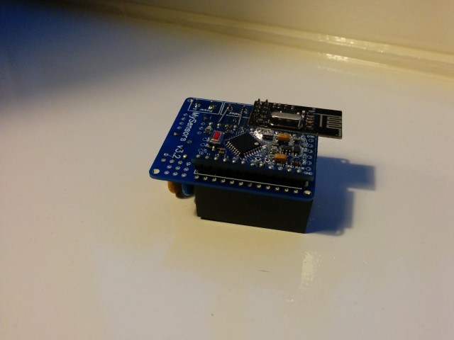
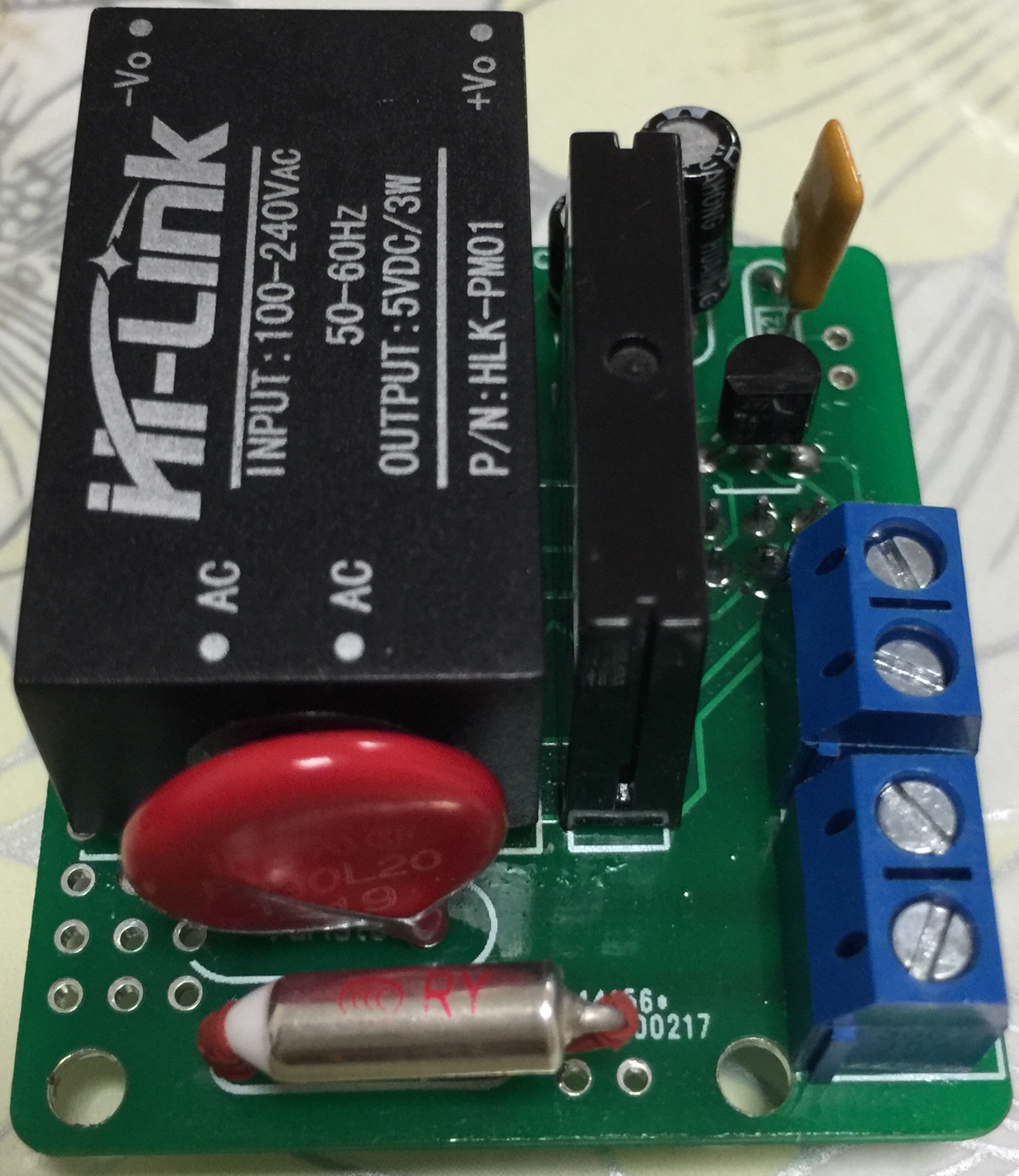
As promised, I've got an update for this project. The board has been tested in the past week, and everything is working as expected. Compared to the previous board I've posted, I have updated the following:
• Solder pads of LE33CZ have been placed a little wider apart to avoid short circuit while soldering.
• Solder pads of the resettable fuse (Fuse2) has been placed closer together to better fit the fuses of the BOM.
• Moved the NRF24L01 connector a bit away from the solid state relay. Should make it easier to solder.
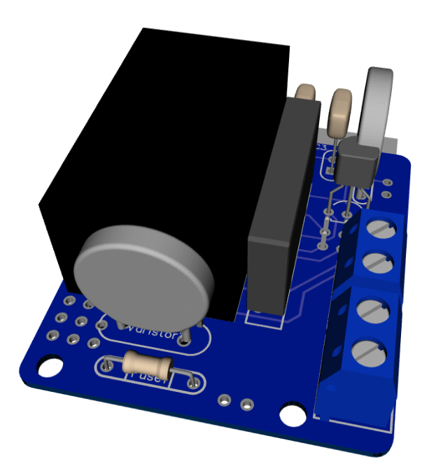
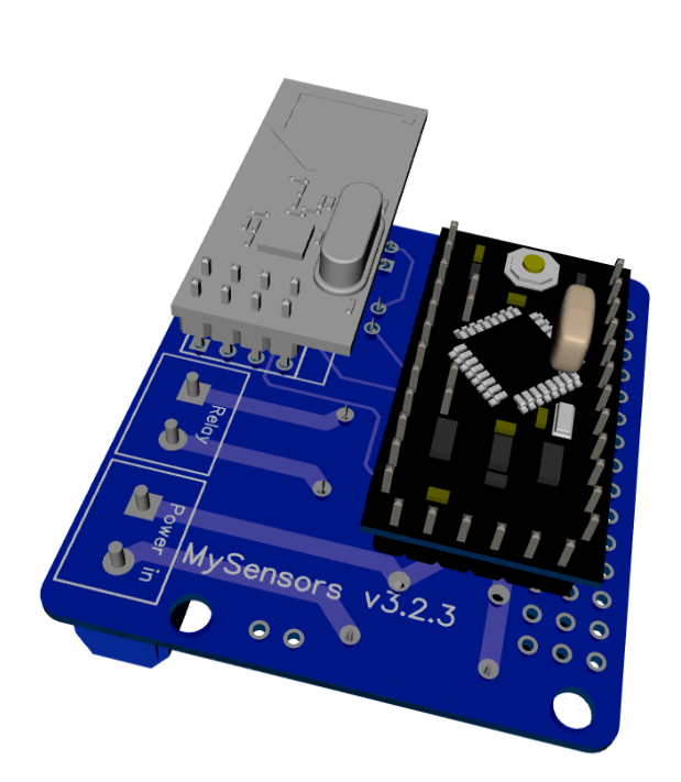
• Moved Fuse2 to another location on the board, away from the 230v circuit.Some 3D pictures (Top and bottom):
Anyone who is interested can order the PCB HERE
Some documentation, complete list of required components and all gerber / DipTrace files (in case you would like to make some modifications) can be found here: MySensors board v3.2.3.zip.
@aproxx hi wonderful design , i was going to make a similar but i can't find EAGLE part and footprint
for HLK-PM01 ,and actually i don't know how to design the part library .
so please if you can share it i will be thankful -
@punter9 check our hardware site openhardware.io