Which are the *best* NRF24L01+ modules?
-
Register 6 (RF_SETUP) bit 7 (CONT_WAVE) on p 55 of the rev 1 datasheet.
Set it up to transmit constantly (carrier only, no data) and measure the Vcc current usage. (For a short time obviously!) Probably close to the current it would take while sending data.
Likewise, measure current while waiting to receive with no actual data coming in (unless that's what your standby is).
I haven't tried the constant-wave transmit mode, I just remembered that it was mentioned in the datasheet.
-
For the IcStation module I profiled directly above, the receive current (using the microcurrent) measures out at 8.4mA using this sketch to put the module into receive mode:
/* Adapted by NeverDie on 8/11/2015 for uCurrent measurements.
 *  Sketch for measuring receive current.
 */

/*
 Copyright (C) 2011 J. Coliz <maniacbug@ymail.com>

 This program is free software; you can redistribute it and/or
 modify it under the terms of the GNU General Public License
 version 2 as published by the Free Software Foundation.

 TMRh20 2014 - Updates to the library allow sleeping both in TX and RX modes:
      TX Mode: The radio can be powered down (.9uA current) and the Arduino slept using the watchdog timer
      RX Mode: The radio can be left in standby mode (22uA current) and the Arduino slept using an interrupt pin
 */

/**
 * Example RF Radio Ping Pair which Sleeps between Sends
 *
 * This is an example of how to use the RF24 class to create a battery-
 * efficient system.  It is just like the GettingStarted_CallResponse example, but the
 * ping node powers down the radio and sleeps the MCU after every
 * ping/pong cycle, and the receiver sleeps between payloads.
 *
 * Write this sketch to two different nodes,
 * connect the role_pin to ground on one.  The ping node sends the current
 * time to the pong node, which responds by sending the value back.  The ping
 * node can then see how long the whole cycle took.
 */

#include <SPI.h>
#include <avr/sleep.h>
#include <avr/power.h>
#include "nRF24L01.h"
#include "RF24.h"
#include "printf.h"


// Set up nRF24L01 radio on SPI bus plus pins 7 & 8
RF24 radio(7,8);

// sets the role of this unit in hardware.  Connect to GND to be the 'pong' receiver
// Leave open to be the 'ping' transmitter
const int role_pin = 5;

const uint64_t pipes[2] = { 0xF0F0F0F0E1LL, 0xF0F0F0F0D2LL };   // Radio pipe addresses for the 2 nodes to communicate.

// Role management
// Set up role.  This sketch uses the same software for all the nodes
// in this system.  Doing so greatly simplifies testing.  The hardware itself specifies
// which node it is.

// The various roles supported by this sketch
typedef enum { role_ping_out = 1, role_pong_back } role_e;

// The debug-friendly names of those roles
const char* role_friendly_name[] = { "invalid", "Ping out", "Pong back"};

// The role of the current running sketch
role_e role;

void setup(){

  // set up the role pin
  pinMode(role_pin, INPUT);
  digitalWrite(role_pin,HIGH);
  delay(20); // Just to get a solid reading on the role pin

  // read the address pin, establish our role
  if ( digitalRead(role_pin) )
    role = role_ping_out;
  else
    role = role_pong_back;

  Serial.begin(57600);
  while (!Serial) {
    ; // wait for serial port to connect. Needed for Leonardo only
  }
  printf_begin();
  printf("\n\rRF24/examples/pingpair_sleepy/\n\r");
  printf("ROLE: %s\n\r",role_friendly_name[role]);

  radio.begin();

  // Open pipes to other nodes for communication

  // This simple sketch opens two pipes for these two nodes to communicate
  // back and forth.
  // Open 'our' pipe for writing
  // Open the 'other' pipe for reading, in position #1 (we can have up to 5 pipes open for reading)

  if ( role == role_ping_out ) {
    radio.openWritingPipe(pipes[0]);
    radio.openReadingPipe(1,pipes[1]);
  } else {
    radio.openWritingPipe(pipes[1]);
    radio.openReadingPipe(1,pipes[0]);
  }


  // Dump the configuration of the rf unit for debugging
  radio.printDetails();
}

void loop(){

  radio.startListening();

}
I can't promise to do the other measurements, as I'm facing some deadlines I need to attend to. If anyone else would like to pick up the baton and carry it forward, please feel free.
-
I understand about other deadlines - I appreciate the efforts you have made so far.
Sounds like all that's needed in the final version of your testing is a bent-pin 2x8 connector test shim such as you have described and photographed, and a $400 DVM :-)
-
I understand about other deadlines - I appreciate the efforts you have made so far.
Sounds like all that's needed in the final version of your testing is a bent-pin 2x8 connector test shim such as you have described and photographed, and a $400 DVM :-)
@Zeph said:
Sounds like all that's needed in the final version of your testing is a bent-pin 2x8 connector test shim such as you have described and photographed,
Yes, a 2x4 connector, or I actually used (2) 1x6 female headers (I didn't have 1x4 female headers readily at hand)
and a $400 DVM :-)
I imagine some of the cheaper DVM's would get the job done too. That's another topic entirely though.
I'm not sure where you draw the line on how much testing is enough. I think it probably already is enough. 80/20 rule. :relaxed:
-
Have you decided to toss the blob modules (or put them in the back of the drawers), in favor of genuine Nordic only?
@Zeph said:
Have you decided to toss the blob modules (or put them in the back of the drawers), in favor of genuine Nordic only?
No, at present I still prefer the blob modules. It may yet turn out that there's a better PCB or antenna or something for the genuine chips that will make a huge difference in their effective performance, but so far I'm underwhelmed by the modules with genuine chips. Also, modules with the genuine chips seem to cost around ~$3/each, and so for about only an extra dollar I could have an RFM69HW. Yesterday I ordered a couple Moteino's with the RFM69HW, and so after they arrive I'll see how that goes rather than re-invent the wheel. They were kinda pricey, which is my main reservation about them.
If others are happy with their genuine chip NRF24L01+ modules, then good for them. Unfortunately I can't count myself among them, and so I'm restless to find something and settle on it. My guess is it may be the blob module, or it may be the RFM69.
-
Ah, OK.
I saw the testing as serving two purposes:
- Learning a "power signature" to distinguish variations on the chips
- Finding out how bad (or good) the variants are in regard to power usage
Seems like the first is nailed. The latter has begun to be characterized (thanks to you). The idle and sleep power is substantially greater on the blobs (for example). If the 8.4 ma for Receive is for the blobs, that doesn't sound bad, don't know about transmit.
And if powered by the mains, it doesn't much matter.
@Zeph said:
....don't know about transmit.
Blob module transmit current was about 20ma, (my interpretation of the oscilliscope pictures I posted). I was surprised that the "listening" current was just 8.4ma, because that's lower than the spec sheet for "receiving" current. I don't know, but perhaps "receiving" consumes more current than just "listening."
On a relative scale compared to the other modules, the blob modules obviously consume more current. However, on an absolute scale, they seem like they may be good enough..
And if powered by the mains, it doesn't much matter.
-
@Zeph Looks as though you could use the LTC2440 to measure the sleep and standby currents and read the results with your arduino: http://dangerousprototypes.com/forum/viewtopic.php?f=2&t=4247#p45583
or maybe use one of these breakout boards to similar effect:
http://www.ebay.com/itm/LTC2400-24bit-analog-to-digital-converter-ADC-module-temp-sensor-SPI-AVR-arduino-/111005456125?pt=LH_DefaultDomain_0&hash=item19d870d6fd -
I'm seeing similar results with my radios. I bought these from aliexpress and then after reading the various threads about fakes and the problems people were having, I bought a bunch of authentic modules from ITEAD just to avoid those headaches. The real modules have much cleaner PCB's and better looking solder joints. The two types seem to be able to talk to each other OK but if set two modules at opposite ends of the house (with 2 exterior walls in between as well), the cheap modules still connect and the genuine ones don't. I'm assuming this is similar to what you're seeing with the real modules having a lower transmit power. I'm now regretting spending the extra money on the genuine modules (if anyone in the CONUS wants some genuine modules, PM me and I'll sell you some at my cost).
-
I'm seeing similar results with my radios. I bought these from aliexpress and then after reading the various threads about fakes and the problems people were having, I bought a bunch of authentic modules from ITEAD just to avoid those headaches. The real modules have much cleaner PCB's and better looking solder joints. The two types seem to be able to talk to each other OK but if set two modules at opposite ends of the house (with 2 exterior walls in between as well), the cheap modules still connect and the genuine ones don't. I'm assuming this is similar to what you're seeing with the real modules having a lower transmit power. I'm now regretting spending the extra money on the genuine modules (if anyone in the CONUS wants some genuine modules, PM me and I'll sell you some at my cost).
Thank you! Finally some confirmation of what I've been saying.
I received some "genuine" modules from AliExpress today: http://www.aliexpress.com/item/Free-shipping-Original-Genuine-NRF24L01-Wireless-Module-2-4G-wireless-communication-module-2-54mm-Interface-2/1781618813.html
Power Down (Sleep): 0.5uA
Standby: 23.5uA
Listening: 8.6ma
The transmit waveform looks exactly the same as the the module from Itead.Therefore, I deem them genuine.
-
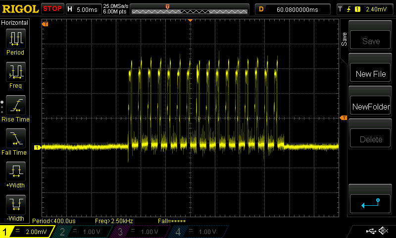
I was able to sharpen my o-scope pictures by turning on Hi-Res mode. With this better detail, a lot more is apparently different between the genuine modules and the blob modules.
Here are some transmit shots of the new genuine modules:

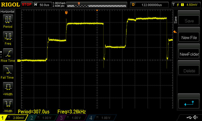
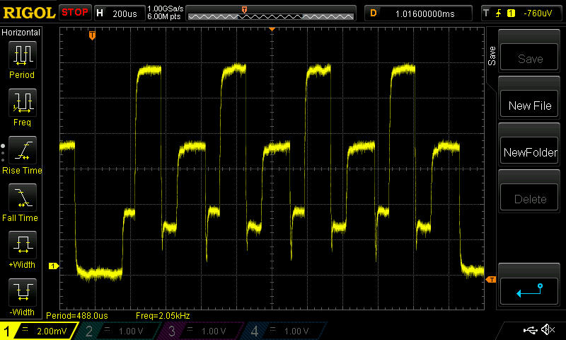
and here are some shots of the blob module, also now taken at Hi-Res on the o-scope:
As you can see now that I'm using Hi-Res mode, even the shapes of the waveforms are completely different looking.
Reminder: because I'm now using a 1/2 ohm sense resister, each verticle devision now represents 4ma.
So, eyeballing it, the genuine chips are using about 12ma for their transmit current, whereas the blob module chips are closer to about 18ma.Also, the second peak after the first peak is higher on the genuine chips, whereas it is lower on the blob chips. I don't know what those peaks represent.
-
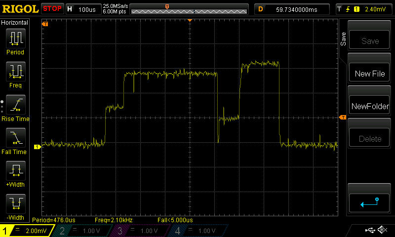
So, for completeness, here's the Hi-Res o-scope pictures of the red module, whose tracecode suggests it may be fake, as previously noted:
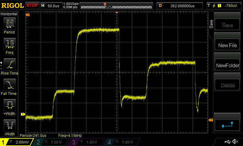
In this case, one thing that jumps out as different than the other two is that the height of the second tall peak is much lower than the first tall peak. In the genuine chip, the second tall peak is actually higher than the first tall peak, so it's quite a distinctive difference.
-
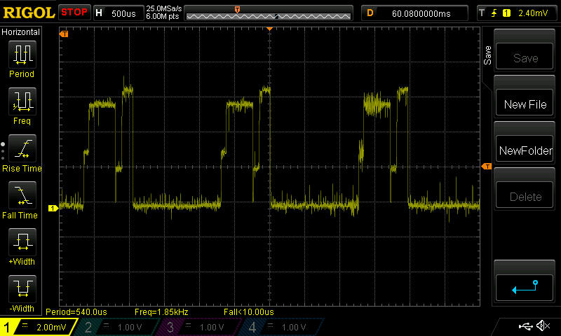
I have a hypothesis for what's going on. According to the NRF24L01+ datasheet,
• 11.3mA TX at 0dBm output power
• 13.5mA RX at 2Mbps air data rateTherefore, I think Mirf probably does a TX, waits for an ACK, and if it isn't found, it tries 3 more times. Therefore, on the genuine chip, you see one tall peak for TX, followed by a second taller peak for RX. It does it again3 times, because, for measurement repeatability, I deliberately removed anything that might receive or ACK its transmissions. So, all the ACKs fail and it transmits 3 more times after the first transmission. That's the hypothesis.
Anyhow, now that I've switched over to the TBRH20 library, this could be checked more easily.
Although already shown above, here it is again for easy reference:
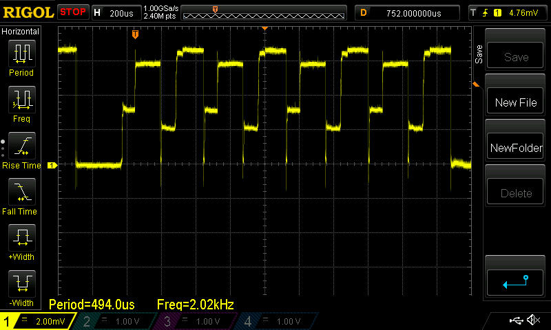
If the hypothesis is true, then the TX and RX currents measure out to exactly what one would expect based on the above specs in the datasheet.
Also, it would explain why it is that before and after the transmission burst, the measured current is the same as the second peak current. That's because the chip is in RX mode between transmissions.
So, from the looks of things, if it doesn't receive an ACK within 250uSeconds (as measured above) after transmission ends, it tries again (up to 3 times). In fact, according to the datasheet, the default for ARD (automatic retransmission delay) is 250 uSeconds. It appears to match up exactly!
-
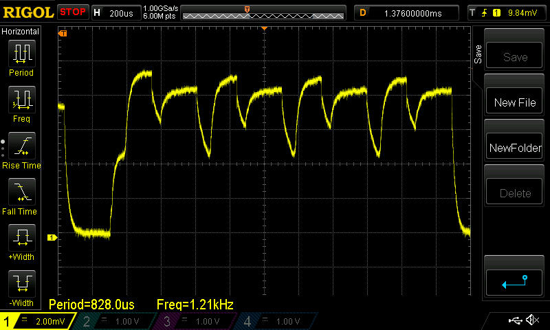
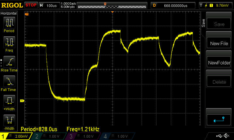
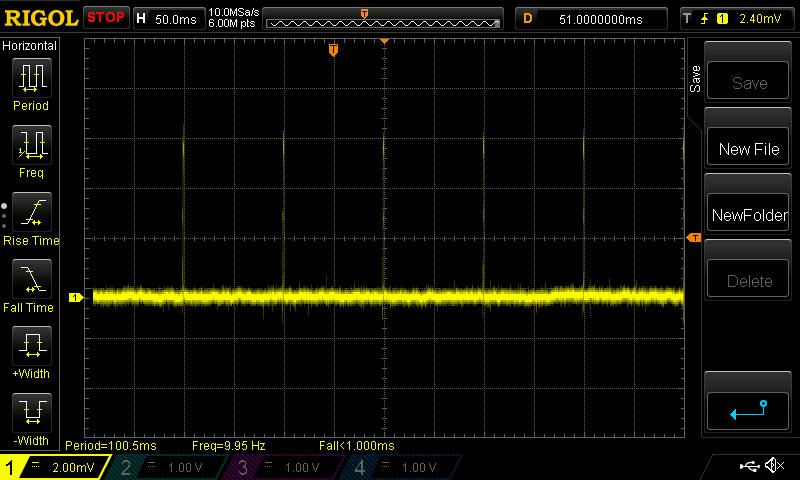
So, indeed, that's what's happening.
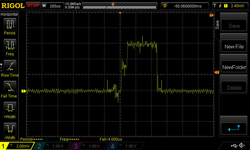
I just switched to TBRH20 and wrote a simple loop to send a packet every 100ms, and to not be listening inbetween. Apparently the default behavior for TBRH20 is to try 16 times to send the packet before giving up!
As before, this is just one shot on the oscilliscope. I'm zooming in on each successive screen by adjusting the time base. I did the measurement on one of the modules with a "genuine" Nordic chip.
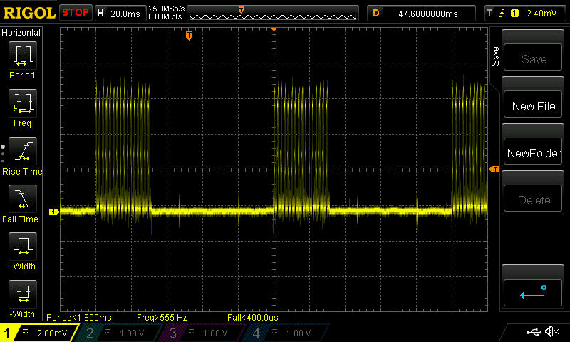
I would guess that in this case TBRH20 is managing the retries in software on the Arduino rather than utilizing the radio chip, because the time between retries is much larger: about 1.5ms.
BTW, I switched to a Mega2560 to do the testing, and, although I haven't yet investigated it, I think the new type of noise that's now evident is probably from the 5v and/or 3v voltage regulator. It doesn't obscure the view, so for now I'm not really concerned.
-
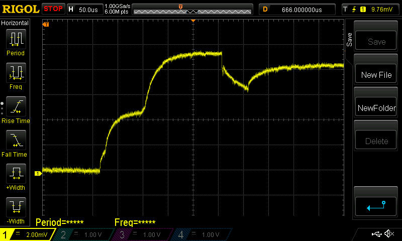
Nailed it. If I explicitly turn ACKing off, then:
What's shown is just a single transmit pulse at 100ms intervals, and with no RX current afterward, as would be required if an ACK was being listened for.
Bottom line: now that the anatomy of the Tx current is known, it should help spot and identify clone chips by comparing their Tx current waveform against that of chips known to be genuine.
-
You've nailed it indeed.
I'm guessing that the first peak on the blob chips is higher because it has higher RF output as well.
If you set bit 0 of register 6 to a 1 on the Blob (unused on the nRF24L01+), and if this chip is a Si24R01 or derivative, it will switch from +2~3dBm to +7dBm RF output, and probably draw even more power.
-
I'm seeing similar results with my radios. I bought these from aliexpress and then after reading the various threads about fakes and the problems people were having, I bought a bunch of authentic modules from ITEAD just to avoid those headaches. The real modules have much cleaner PCB's and better looking solder joints. The two types seem to be able to talk to each other OK but if set two modules at opposite ends of the house (with 2 exterior walls in between as well), the cheap modules still connect and the genuine ones don't. I'm assuming this is similar to what you're seeing with the real modules having a lower transmit power. I'm now regretting spending the extra money on the genuine modules (if anyone in the CONUS wants some genuine modules, PM me and I'll sell you some at my cost).
@TD22057 said:
I'm seeing similar results with my radios. ... The two types seem to be able to talk to each other OK but if set two modules at opposite ends of the house (with 2 exterior walls in between as well), the cheap modules still connect and the genuine ones don't. I'm assuming this is similar to what you're seeing with the real modules having a lower transmit power.
My hypothesis: The blob units have more transmit power (perhaps being Si24R01 or related) and thus a higher first peak, but perhaps no better receive sensitivity.
If so a blob to genuine would have at least as good a range as blob to blob, and a genuine to blob would have similar range as a genuine to genuine.
Of course testing that may involve a one way transmission, where we check for lost packets on the receive side (without expecting a round trip).
If however the blobs have managed to beat the genuine receive sensitivity, then they are really hot stuff!
-
@TD22057 said:
I'm seeing similar results with my radios. ... The two types seem to be able to talk to each other OK but if set two modules at opposite ends of the house (with 2 exterior walls in between as well), the cheap modules still connect and the genuine ones don't. I'm assuming this is similar to what you're seeing with the real modules having a lower transmit power.
My hypothesis: The blob units have more transmit power (perhaps being Si24R01 or related) and thus a higher first peak, but perhaps no better receive sensitivity.
If so a blob to genuine would have at least as good a range as blob to blob, and a genuine to blob would have similar range as a genuine to genuine.
Of course testing that may involve a one way transmission, where we check for lost packets on the receive side (without expecting a round trip).
If however the blobs have managed to beat the genuine receive sensitivity, then they are really hot stuff!
@Zeph said:
@TD22057 said:
I'm seeing similar results with my radios. ... The two types seem to be able to talk to each other OK but if set two modules at opposite ends of the house (with 2 exterior walls in between as well), the cheap modules still connect and the genuine ones don't. I'm assuming this is similar to what you're seeing with the real modules having a lower transmit power.
My hypothesis: The blob units have more transmit power (perhaps being Si24R01 or related) and thus a higher first peak, but perhaps no better receive sensitivity.
If so a blob to genuine would have at least as good a range as blob to blob, and a genuine to blob would have similar range as a genuine to genuine.
Of course testing that may involve a one way transmission, where we check for lost packets on the receive side (without expecting a round trip).
If however the blobs have managed to beat the genuine receive sensitivity, then they are really hot stuff!
@Zeph I'm pretty sure the blob modules are using the RFM75 die because the above mA and uA measurements appear to be a good match for the electrical specification on page 22 of http://www.hoperf.com/upload/rf/RFM75 Datasheet v1.0.pdf
Makes me wonder if it would perform the same or differently if it were installed on the manufacturer recommended PCB along with all the recommended passive components, because you can buy proper RFM75 modules cheaper than "genuine" NRF24L01+ modules.
-
Look at this RFM75 module. It's got the blob. It sounds like a bad horror movie.