Low Power: How much current? [Solved]
-
How much current are you drawing, and at what voltage?
As a point of comparison, Rocket Scream's Mini Ultra 8Mhz Arduino from a few years ago was drawing "a minimum of 1.7uA." http://www.rocketscream.com/blog/product/mini-ultra-8-mhz-arduino-compatible/
Anyone beating that? With a radio included, I'd be surprised, but who knows?
If not, let's raise the bar: anyone drawing less than, say, 10uA in power down mode, including radio in power down mode? 20uA? 50uA? 100uA?
Anyone measuring?
-
In my case, like I have already said on some posts.
Measurements done with uCurrent Gold and multimeter, 2x aaa battery.
In Powerdown:- arduino pro mini, with reg and led removed, without anything else connected: 140nA at 3.3v 8Mhz
- with board I designed (booster, supervisor...), same arduino plugged in, nrf24, bh1750, I am under uA near ulpnode results from hallard.me . It oscillates between 500nA-1uA. The difference comes from power circuit management as radio and sensors are shut off by mosfets (one for radio, one for sensors power rail).
So it is under battery discharge.
@scalz said:
In my case, like I have already said on some posts.
Measurements done with uCurrent Gold and multimeter, 2x aaa battery.
In Powerdown:- arduino pro mini, with reg and led removed, without anything else connected: 140nA at 3.3v 8Mhz
- with board I designed (booster, supervisor...), same arduino plugged in, nrf24, bh1750, I am under uA near ulpnode results from hallard.me . It oscillates between 500nA-1uA. The difference comes from power circuit management as radio and sensors are shut off by mosfets (one for radio, one for sensors power rail).
So it is under battery discharge.
Impressive!
Would you mind posting a link to where you describe the details of what you've done? I tried quickly scanning through your prior postings, but it's not jumping out at me. Also, I did a global search for 140na, and this is the only thread where that came up.
-
Here's a well written short article on how to easily bring the power-down sleep current of a $2, 3.3V, 8Mhz, Arduino Pro Mini to 4.5uA in just a few short steps: http://www.home-automation-community.com/arduino-low-power-how-to-run-atmega328p-for-a-year-on-coin-cell-battery/
-
@Neverdie: thx. I already know this. And if you want to go below 1uA you need to disable WDT.
My learning resources for this stuff ultra low power are:- http://www.gammon.com.au/power
- hallard.me
- jeenode
- lowpowerlab
There are lot of tricks to get ulp. with mosfets, pinmode, good reinit of i2c if you shut off...
For the moment my code is just tests. And I need to clean it. Then, I know Charles will release his ulpnode lib soon. And it will focus on all aspects. So I don't need to reinvent the wheel, and will try to help Charles if I can, to improve it, and thank to him. So I focus on my others projects, waiting my pcb and the lib to see. -
@Neverdie: thx. I already know this. And if you want to go below 1uA you need to disable WDT.
My learning resources for this stuff ultra low power are:- http://www.gammon.com.au/power
- hallard.me
- jeenode
- lowpowerlab
There are lot of tricks to get ulp. with mosfets, pinmode, good reinit of i2c if you shut off...
For the moment my code is just tests. And I need to clean it. Then, I know Charles will release his ulpnode lib soon. And it will focus on all aspects. So I don't need to reinvent the wheel, and will try to help Charles if I can, to improve it, and thank to him. So I focus on my others projects, waiting my pcb and the lib to see.@scalz said:
@Neverdie: thx. I already know this.
Sorry, I should have addressed it to @!scalz, or else <@noobs> or something, as I meant it for others with interest in the topic who maybe hadn't started yet. The sites you cited are good and have their place, but for a noob they may look daunting. In contrast, the site I cited above, while not as advanced or as effective as what you're doing, still offers huge results for very little effort. Also, since you hadn't said how you achieved your low current, there needs to be some baseline, which it helps establish. In particular what I liked about it is what can be achieved with relative ease with a simple, off-the-shelf, $2 Arduino Mini Pro, which until there are better options is what I'm likely to deploy because of its low cost, small size, and (with simple mods anyone can do) remarkably low power. In contrast, for example, Gammon advocates using a barebones arduino (basically the DIP chip itself and maybe only a little more), which, for many, would be harder to deploy because it lacks common header pins on a PCB format that they're familiar with.
-
@NeverDie great article about low power easy to read and doable . I will be using this info and trying the coin battery method for my remote application coming up!
-
@Sparkman said:
@5546dug @NeverDie One thing to be cautious of is that not all Mini's use the same board configuration so the instructions may need to be altered depending on exactly with Mini you have.
Cheers
AlAt the moment I'm wondering whether different Pro Mini's might consume more power than others, even if setup the same. I followed the author's directions, but I'm getting 17uA of current in power-down sleep mode (forever), not the 4.5uA that the author claims to have measured on his. Maybe it has to do with the configuration differences you're referring to? Or, I suppose it could be measurement error (either mine or the author's or both). I'm using a uCurrent Gold in conjunction with a Fluke 87V to do my measurements. The author didn't say how he did his, so I sent him an email asking for the details of how he measured.
I am pleased though at having gotten such a gigantic reduction by following such a simple 3 step process.
-
@NeverDie Experience the same... even though I have same boards/same batch and same actions to reduce power they are difference in how fast they drain battery.
Controller: Proxmox VM - Home Assistant
MySensors GW: Arduino Uno - W5100 Ethernet, Gw Shield Nrf24l01+ 2,4Ghz
MySensors GW: Arduino Uno - Gw Shield RFM69, 433mhz
RFLink GW - Arduino Mega + RFLink Shield, 433mhz -
@NeverDie Experience the same... even though I have same boards/same batch and same actions to reduce power they are difference in how fast they drain battery.
@sundberg84 said:
@NeverDie Experience the same... even though I have same boards/same batch and same actions to reduce power they are difference in how fast they drain battery.
What magnitude of variation are you noticing? e.g. what are the high and low numbers?
-
@NeverDie Sorry i dont have the equipment for numbers... Only some run out of batteries in 3 month and some last for... A very long time.
-
I have a hunch as to what's causing my higher current drain. I took a more careful look at the author's photo, and it looks as though he didn't solder evem a single wire to the board. Rather, it appears he connected Vcc and Ground through probe clips or something.
In my case, I soldered on 30 header pins, and so my hunch is that the residual solder flux is causing a current drain that may account for much of the difference between the author's measurements and mine.
I'll try the author's three steps again on a new Pro Mini board, equivalent to the first, but this time I won't solder on any header pins.
@NeverDie said:
I have a hunch as to what's causing my higher current drain. I took a more careful look at the author's photo, and it looks as though he didn't solder evem a single wire to the board. Rather, it appears he connected Vcc and Ground through probe clips or something.
In my case, I soldered on 30 header pins, and so my hunch is that the residual solder flux is causing a current drain that may account for much of the difference between the author's measurements and mine.
I'll try the author's three steps again on a new Pro Mini board, equivalent to the first, but this time I won't solder on any header pins.
Apparently not. I couldn't find another Pro Mini board of the same design, so I tried one with a different design, but this time I didn't solder anything. I followed the same steps as before, and I got the very same 17.2uA as I got before with the Pro Mini that I soldered 30 header pins on.
So, same current measured on different boards, but connected differently. Unless someone has an alternate theory, it seems to me like that maybe really is the current.
Anyone else tried it and measured it? The three steps take less than 5 minutes. You just remove two components (or remove one component and cut a trace to the other) and upload a "deep sleep forever" script and then you're ready to take measurements.
-
@Neverdie: I am not at home today. But I remember that I had difference using lowpowerlab lib. Very strange. So I started to write my own function.
One trick to check if you want: test sketch J from http://www.gammon.com.au/forum/?id=11497
I had better result with it. -
OK I am going to join the party as this is exactly what I have been testing this past week. I have a uCurrent Gold and running on an 8Mhz 3.3v Nano Pro from this site:
https://www.sparkfun.com/products/11114
I have un-soldered the smt jumper to bypass all voltage regulating and running off of 2 AA Batteries.
I am using the BinarySwitchSleepSensor sketch from the MySensors library. This uses pin 2/3 as an interrupt and sleeps until a pin hits GND. It wakes up, sends the new state, and goes back to sleep. The sketch also makes pin 2/3 high and uses the internal pull-up resistor.
Originally I was getting 23-24uA in sleep mode when GND was not connected to pin 2/3. 117uA when GND was connected to pin 2/3. We will refer to this as open and closed pin state.
Here is my methods:
I downgraded my version of Arduino IDE to 1.0.6 from the latest build 1.6.5 and here are my new numbers:2.5-2.7uA sleep mode - Open pin state
98-100uA sleep mode - Closed pin stateThen I deleted from the sketch the digitalWrite on pin 2/3 and used an external resistor thanks to the advice from AWI. I plugged in an 10M Resistor to pin 2 to VCC and GND was the switch. Here are my new numbers:
2.5-2.7uA sleep mode - Open pin state
3.1-3.2uA sleep mode - Closed pin stateSo far today I have not gotten any false positives in my setup which is freaking amazing.
Now I used a quick sketch "DallasTemperatureSensor" from the MySensors library to test what my current would be in sleep mode with a watchdog timer. I did NOT connect a temp sensor but my sleep current is: 7.6uA - 7.8uA.
I hope this helps and if you need any testing let me know.
I have a post on the Arduino forums here:
http://forum.arduino.cc/index.php?topic=341958.msg2360300#msg2360300You can see me talking to the guy who actually wrote up the gammon website and you can ask him things directly if you ever wanted too. Very helpful guy!
-
Thanks! Very timely, as I was just now hunting for a 3.3v 8Mhz Pro Mini that might work.
Sparkman is right. Now that I'm looking more closely, I'm finding that there are a lot of "configurations" of the pro mini. Amazon is selling some (possibly fake) Sparkfun pro mini's that superficially resemble the one brolly759 has, except they're missing the solder jumper, and some of the passives look smaller.
http://www.amazon.com/gp/product/B00JNYXC8Q/ref=ox_sc_act_title_1?ie=UTF8&psc=1&smid=A1LHQ5G6ONPXVT
http://www.amazon.com/gp/product/B00Q9YAP2E/ref=ox_sc_act_title_2?ie=UTF8&psc=1&smid=A34K5WF5Z9R33P
I'm in a bit of a hurry because I don't want to lose momentum, so I'll be the guinea pig and order the red ones. If they don't measure out well, then I'll order one direct from Sparkfun.
Ultimately, though, I'd like to find a source for a truly low power "configuration" at closer to the $2 from China. If that's not possible, then before giving up I want to at least understand why it's not possible.
-
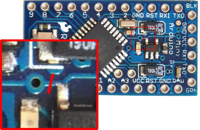
I think at one time, the pro mini did not have the power jumper and china copies the boards and resells them. They probably never refreshed the product line. Here is an article in 2013 of someone trying to do low power on the boards that you are referring too:
Here is the trace you need to cut to bypass all the voltage regulation crap:
link textIf you have one of the cheap boards, I would cut the PCB trace first and retest before buying new stuff. Let me know what happens.
-
@Neverdie: during my low power tests, I have used these http://s.click.aliexpress.com/e/feUvNFufi and it worked like I said. Arduino pro mini, I think you know it, is basically an atmel with some components. And I think most of arduino clones follow Arduino reference schematics. Just rooting and placements is different. So, in theory, it should work. but maybe bad components like capa, and I am not sure, could be the cause. but, in this case, it means that you can't be sure with all clones too and you need to find the good supplier. very strange and not cool. or maybe could it be counterfeil atmel...I don't think.
Did you tried Sketch J from Gammon. Do you have still the problem??
And of course like Brolly said, I removed voltage reg stuff.