Skip to content
  • OpenHardware.io
  • Categories
  • Recent
  • Tags
  • Popular
Skins
  • Light
  • Brite
  • Cerulean
  • Cosmo
  • Flatly
  • Journal
  • Litera
  • Lumen
  • Lux
  • Materia
  • Minty
  • Morph
  • Pulse
  • Sandstone
  • Simplex
  • Sketchy
  • Spacelab
  • United
  • Yeti
  • Zephyr
  • Dark
  • Cyborg
  • Darkly
  • Quartz
  • Slate
  • Solar
  • Superhero
  • Vapor

  • Default (No Skin)
  • No Skin
Collapse
Brand Logo
  1. Home
  2. Hardware
  3. MySensors shield and RGBW Controller
  • Getting Started
  • Controller
  • Build
  • Hardware
  • Download/API
  • Forum
  • Store

MySensors shield and RGBW Controller

Scheduled Pinned Locked Moved Hardware
66 Posts 16 Posters 32.1k Views 21 Watching
  • Oldest to Newest
  • Newest to Oldest
  • Most Votes
Reply
  • Reply as topic
Log in to reply
This topic has been deleted. Only users with topic management privileges can see it.
  • L Offline
    L Offline
    LastSamurai
    Hardware Contributor
    wrote on last edited by
    #41

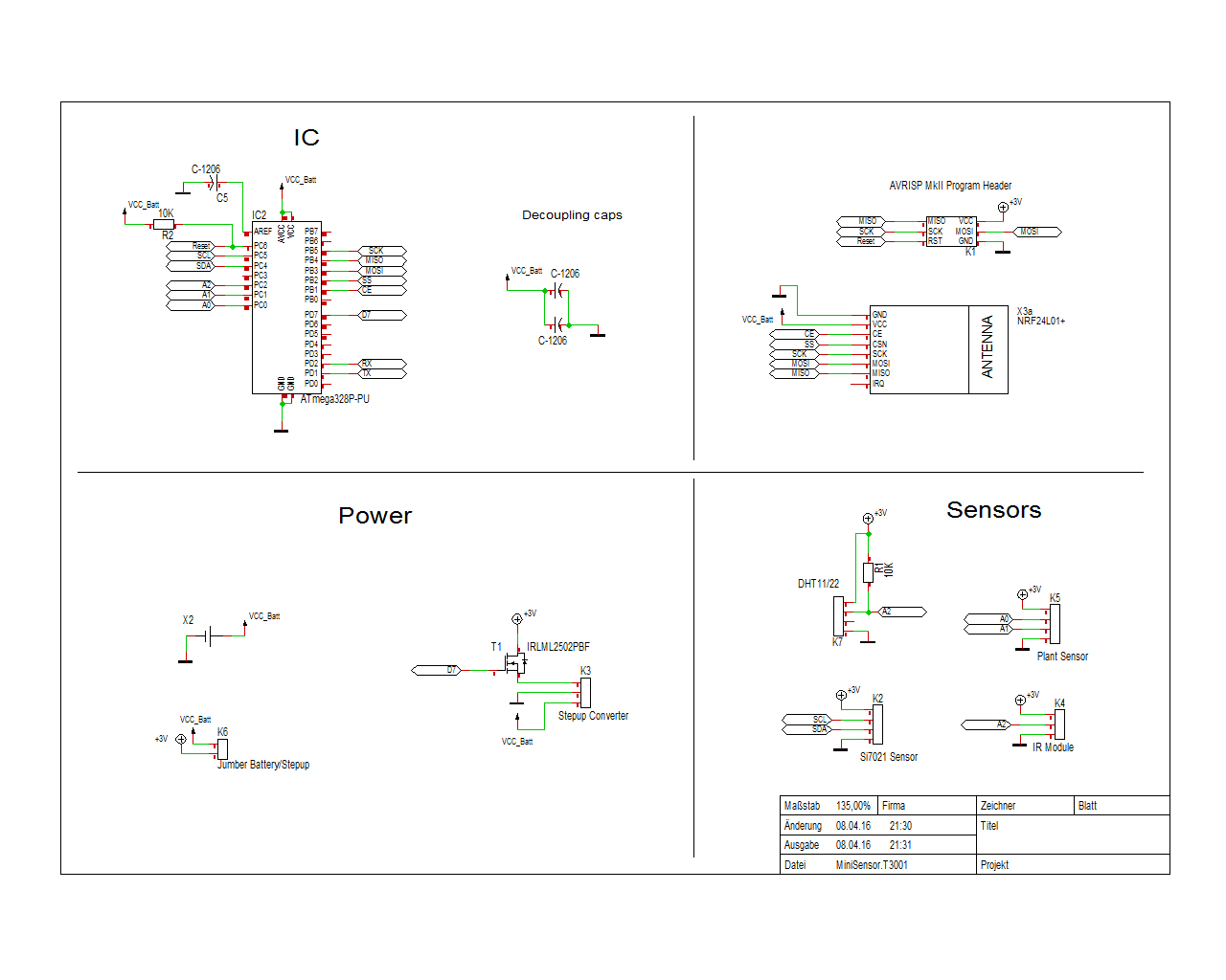
    I just realized that I forgot to actually forgot to add the schematics... hard for you guys to help like that^^. So here they are, I hope you guys find some errors that I overlooked ;)

    0_1460320572976_MiniSensor.jpg

    1 Reply Last reply
    0
    • L Offline
      L Offline
      LastSamurai
      Hardware Contributor
      wrote on last edited by
      #42

      Any feedback? I will keep working on it for the next days. I am also thinking about adding some kind of light sensor. What is the cheapest one that works well with <=3.3V? What do you guys use?

      1 Reply Last reply
      0
      • GertSandersG Offline
        GertSandersG Offline
        GertSanders
        Hardware Contributor
        wrote on last edited by
        #43

        I use an LDR

        1 Reply Last reply
        0
        • L Offline
          L Offline
          LastSamurai
          Hardware Contributor
          wrote on last edited by
          #44

          @GertSanders Thanks, that seems to be the easiest solution.
          I am still working on the board so any mistake you guys might find... tell me :)

          I finally got around to post the RGBW controller part on openhardware.io. Here is the discussion thread.

          1 Reply Last reply
          1
          • L Offline
            L Offline
            LastSamurai
            Hardware Contributor
            wrote on last edited by
            #45

            Does anyone have a link (ebay aliexpress) or name for a nice coincell holder that I can use for my pcb. I used to use some with 2 pins as a connection to the pcb and a plane and some kind of sping on the other side. These work well but its very hard to get the coin cells out again when testing. I saw some pictures of coin cell holders where you just push the cell in from the side but can't find them online.

            Also do you guys know any other sensors that could be of use (so that I can integrate them here) or see any errors in my schematics? Otherwise I can hopefully do the pcb design later this week and finally order the boards.

            GertSandersG 1 Reply Last reply
            0
            • L LastSamurai

              Does anyone have a link (ebay aliexpress) or name for a nice coincell holder that I can use for my pcb. I used to use some with 2 pins as a connection to the pcb and a plane and some kind of sping on the other side. These work well but its very hard to get the coin cells out again when testing. I saw some pictures of coin cell holders where you just push the cell in from the side but can't find them online.

              Also do you guys know any other sensors that could be of use (so that I can integrate them here) or see any errors in my schematics? Otherwise I can hopefully do the pcb design later this week and finally order the boards.

              GertSandersG Offline
              GertSandersG Offline
              GertSanders
              Hardware Contributor
              wrote on last edited by
              #46

              @LastSamurai
              Look for Keystone Technologies. They make the battery holder on the Adafruit RTC breakout.

              L 1 Reply Last reply
              0
              • GertSandersG GertSanders

                @LastSamurai
                Look for Keystone Technologies. They make the battery holder on the Adafruit RTC breakout.

                L Offline
                L Offline
                LastSamurai
                Hardware Contributor
                wrote on last edited by LastSamurai
                #47

                @GertSanders Thanks you very much but I just can't find any of them (at least at a reasonable price) on aliexpres or ebay(.de).
                Should you (or someone else) know a link to one, please send it to me!

                1 Reply Last reply
                0
                • L Offline
                  L Offline
                  LastSamurai
                  Hardware Contributor
                  wrote on last edited by LastSamurai
                  #48

                  So I got my pcbs yesterday and started to test them. After some problems with power supply (here) I got the pro mini + nrf to work and send/receive commands. Today I connected the led lights and nothing happened (although it should start with a little power on all channels). After some time of testing to figure out the error the AMS suddenly got very hot and I disconnected the power as fast as possible. Now the pro mini doesn't react anymore to programming (or even serial in/output). I think I somehow broke it. Before I destroy another one though:
                  do you guys have any idea if there might be an error in my schematics (especially concerning the mosfet part)?

                  The schematics are in the pdf:
                  link text

                  This is my current code:

                  /**
                  Based on the MySensors Project: http://www.mysensors.org
                  
                  This sketch controls a (analog)RGBW strip by listening to new color values from a (domoticz) controller and then fading to the new color.
                  
                  Version 1.0 - Changed pins and gw definition
                  Version 0.9 - First version
                  
                  TODO
                  safe/request values after restart/loss of connection
                  */
                  
                  
                  #define SN   "RGBW test"
                  #define SV   "v1.0 29042016"
                  
                  // Load mysensors library	
                  #include <MySensor.h>	
                  // Load Serial Peripheral Interface library  
                  #include <SPI.h>
                  
                  // Arduino pin attached to driver pins
                  #define RED_PIN 3 
                  #define WHITE_PIN 9	// this is not a pwm pin! change it if you want pwm
                  #define GREEN_PIN 5
                  #define BLUE_PIN 6
                  #define NUM_CHANNELS 4 // how many channels, RGBW=4 RGB=3...
                  
                  #define SENSOR_ID 1
                  
                  // Smooth stepping between the values
                  #define STEP 1
                  #define INTERVAL 10
                  const int pwmIntervals = 255;
                  float R; // equation for dimming curve
                  
                  // change the pins to free up the pwm pin for led control
                  #define RF24_CE_PIN   4 //<-- NOTE!!! changed, the default is 9
                  #define RF24_CS_PIN   10  // default is 10
                  #define RF24_PA_LEVEL RF24_PA_MAX
                  
                  MyTransportNRF24 transport(RF24_CE_PIN, RF24_CS_PIN, RF24_PA_LEVEL);
                  MySensor gw(transport);	
                     
                  // Stores the current color settings
                  byte channels[4] = {RED_PIN, GREEN_PIN, BLUE_PIN, WHITE_PIN};
                  byte values[4] = {100, 100, 100, 100};
                  byte target_values[4] = {100, 100, 100, 100}; 
                  
                  
                  // stores dimming level
                  byte dimming = 100;
                  byte target_dimming = 100;
                  
                  // tracks if the strip should be on of off
                  boolean isOn = true;
                  
                  // time tracking for updates
                  unsigned long lastupdate = millis();
                       
                  void setup() 
                  {
                    // Initializes the sensor node (with callback function for incoming messages)
                    gw.begin(incomingMessage);	// 123 = node id for testing	
                         
                    // Present sketch (name, version)
                    gw.sendSketchInfo(SN, SV);				
                         
                    // Register sensors (id, type, description, ack back)
                    gw.present(SENSOR_ID, S_RGBW_LIGHT, "RGBW test light", true);
                  
                    // request current values from gateway/controller
                    //gw.request(SENSOR_ID, S_RGBW_LIGHT);
                  
                    // Set all channels to output (pin number, type)
                    for (int i = 0; i < NUM_CHANNELS; i++) {
                      pinMode(channels[i], OUTPUT);
                    }
                  
                    // set up dimming
                    R = (pwmIntervals * log10(2))/(log10(255));
                  
                    // init lights
                    updateLights();
                    
                    // debug
                    if (isOn) {
                      Serial.println("RGBW is running...");
                    }
                   
                    Serial.println("Waiting for messages...");  
                  }
                  
                  void loop()
                  {
                    // Process incoming messages (like config and light state from controller) - basically keep the mysensors protocol running
                    gw.process();		
                  
                    // and set the new light colors
                    if (millis() > lastupdate + INTERVAL) {
                      updateLights();
                      lastupdate = millis();
                    } 
                  }
                  
                  // callback function for incoming messages
                  void incomingMessage(const MyMessage &message) {
                  
                    Serial.print("Got a message - ");
                    Serial.print("Messagetype is: ");
                    Serial.println(message.type);
                  
                    // acknoledgment
                    if (message.isAck())
                    {
                     	Serial.println("Got ack from gateway");
                    }
                    
                    // new dim level
                    else if (message.type == V_DIMMER) {
                        Serial.println("Dimming to ");
                        Serial.println(message.getString());
                        target_dimming = message.getByte();
                    }
                  
                    // on / off message
                    else if (message.type == V_STATUS) {
                      Serial.print("Turning light ");
                  
                      isOn = message.getInt();
                  
                      if (isOn) {
                        Serial.println("on");
                      } else {
                        Serial.println("off");
                      }
                    }
                  
                    // new color value
                    else if (message.type == V_RGBW) {    
                      const char * rgbvalues = message.getString();
                      inputToRGBW(rgbvalues);    
                    }  
                  }
                  
                  // this gets called every INTERVAL milliseconds and updates the current pwm levels for all colors
                  void updateLights() {  
                  
                    // update pin values -debug
                    //Serial.println(greenval);
                    //Serial.println(redval);
                    //Serial.println(blueval);
                    //Serial.println(whiteval);
                  
                    //Serial.println(target_greenval);
                    //Serial.println(target_redval);
                    //Serial.println(target_blueval);
                    //Serial.println(target_whiteval);
                    //Serial.println("+++++++++++++++");
                  
                    // for each color
                    for (int v = 0; v < NUM_CHANNELS; v++) {
                  
                      if (values[v] < target_values[v]) {
                        values[v] += STEP;
                        if (values[v] > target_values[v]) {
                          values[v] = target_values[v];
                        }
                      }
                  
                      if (values[v] > target_values[v]) {
                        values[v] -= STEP;
                        if (values[v] < target_values[v]) {
                          values[v] = target_values[v];
                        }
                      }
                    }
                  
                    // dimming
                    if (dimming < target_dimming) {
                      dimming += STEP;
                      if (dimming > target_dimming) {
                        dimming = target_dimming;
                      }
                    }
                    if (dimming > target_dimming) {
                      dimming -= STEP;
                      if (dimming < target_dimming) {
                        dimming = target_dimming;
                      }
                    }
                  
                    /*
                    // debug - new values
                    Serial.println(greenval);
                    Serial.println(redval);
                    Serial.println(blueval);
                    Serial.println(whiteval);
                  
                    Serial.println(target_greenval);
                    Serial.println(target_redval);
                    Serial.println(target_blueval);
                    Serial.println(target_whiteval);
                    Serial.println("+++++++++++++++");
                    */
                  
                    // set actual pin values
                    for (int i = 0; i < NUM_CHANNELS; i++) {
                      if (isOn) {
                        // normal fading
                        // analogWrite(channels[i], dimming / 100 * values[i]);
                        // non linear fading, idea from https://diarmuid.ie/blog/pwm-exponential-led-fading-on-arduino-or-other-platforms/
                        analogWrite(channels[i], pow (2, (values[i] / R)) - 1);
                      } else {
                        analogWrite(channels[i], 0);
                      }
                    }
                  }
                  
                  // converts incoming color string to actual (int) values
                  // ATTENTION this currently does nearly no checks, so the format needs to be exactly like domoticz sends the strings
                  void inputToRGBW(const char * input) {
                    Serial.print("Got color value of length: "); 
                    Serial.println(strlen(input));
                    
                    if (strlen(input) == 6) {
                      Serial.println("new rgb value");
                      target_values[0] = fromhex (& input [0]);
                      target_values[1] = fromhex (& input [2]);
                      target_values[2] = fromhex (& input [4]);
                      target_values[3] = 0;
                    } else if (strlen(input) == 9) {
                      Serial.println("new rgbw value");
                      target_values[0] = fromhex (& input [1]); // ignore # as first sign
                      target_values[1] = fromhex (& input [3]);
                      target_values[2] = fromhex (& input [5]);
                      target_values[3] = fromhex (& input [7]);
                    } else {
                      Serial.println("Wrong length of input");
                    }  
                  
                  
                    Serial.print("New color values: ");
                    Serial.println(input);
                    
                    for (int i = 0; i < NUM_CHANNELS; i++) {
                      Serial.print(target_values[i]);
                      Serial.print(", ");
                    }
                   
                    Serial.println("");
                    Serial.print("Dimming: ");
                    Serial.println(dimming);
                  }
                  
                  // converts hex char to byte
                  byte fromhex (const char * str)
                  {
                    char c = str [0] - '0';
                    if (c > 9)
                      c -= 7;
                    int result = c;
                    c = str [1] - '0';
                    if (c > 9)
                      c -= 7;
                    return (result << 4) | c;
                  }
                  
                  1 Reply Last reply
                  0
                  • L Offline
                    L Offline
                    LastSamurai
                    Hardware Contributor
                    wrote on last edited by
                    #49

                    I finally found the mistake (with some help). The pins for the mosfets were switched. I rotatet them and now its working perfectly. Smooth dimming and switching between colors is really cool. New pictures are on my openhardware.io project page.
                    Now I need to get some more features for the code (linear fading, remembering the values after restarts...) and then perhaps sometime in the future a better (and fixed) version of the pcb.

                    1 Reply Last reply
                    1
                    • A Offline
                      A Offline
                      activemind
                      wrote on last edited by
                      #50

                      @LastSamurai This is a very nice and useful board you have here. But I was more interested in the first PCB you made with heftier FETs. Would it be okay if I took that first rev as a base and modified it for my needs. I need a VERY simple 3 channel (RGB) controller with hefty (> 5A) FETs.

                      How do I access the board files of that first rev to use them as base?

                      -AM

                      1 Reply Last reply
                      0
                      • L Offline
                        L Offline
                        LastSamurai
                        Hardware Contributor
                        wrote on last edited by
                        #51

                        @activemind said:

                        @LastSamurai This is a very nice and useful board you have here. But I was more interested in the first PCB you made with heftier FETs. Would it be okay if I took that first rev as a base and modified it for my needs. I need a VERY simple 3 channel (RGB) controller with hefty (> 5A) FETs.

                        How do I access the board files of that first rev to use them as base?

                        -AM

                        Thanks you! The old files are here I think. It has been done with Target3001 and kicad. You could just take my newest board and replace the FETs. Or just order my boards and solder the FETs onto the smd pads (not perfect but should work too).
                        I did some updates in the newer versions so be carefull to catch that (e.g. use pwm pins for all 4 colors).

                        Once I find the time I'll upload some pictures here too. At the moment I am using 3 of my boards to light up a room. Looks very nice imho.

                        1 Reply Last reply
                        0
                        • A Offline
                          A Offline
                          activemind
                          wrote on last edited by
                          #52

                          Thanks @LastSamurai . I went ahead and ordered v1.3 of the board just to try them out. If I can solder heftier FETs then your board is EXACTLY what I am looking for. I dont care much about 4th channel since all of my applications will be high power RGB floods.

                          I didnt look too closely but is there provision for current limiting ressistors in each of the channels.

                          I will go ahead and load your files in KiCad and see if I can find my way around. Never done any PCB dev but want to give it a try :-)

                          -AM

                          L 1 Reply Last reply
                          0
                          • A activemind

                            Thanks @LastSamurai . I went ahead and ordered v1.3 of the board just to try them out. If I can solder heftier FETs then your board is EXACTLY what I am looking for. I dont care much about 4th channel since all of my applications will be high power RGB floods.

                            I didnt look too closely but is there provision for current limiting ressistors in each of the channels.

                            I will go ahead and load your files in KiCad and see if I can find my way around. Never done any PCB dev but want to give it a try :-)

                            -AM

                            L Offline
                            L Offline
                            LastSamurai
                            Hardware Contributor
                            wrote on last edited by LastSamurai
                            #53

                            @activemind Cool, I guess you are the first one (beside me^^) using these boards. It's nice to see that my work can help others. Some feedback later on would be great :+1:

                            Current limiting resistors are not part of the board atm. Did not really need them. I only added pulldowns to the control lines.
                            But just have a look with kicad; the program (while having some strange menues/shortcuts) isn't that hard to learn and if you continue to work with electronics its a nice skill to have. I am 100% selft taught and my designs (mostly :stuck_out_tongue_closed_eyes: ) work.

                            1 Reply Last reply
                            0
                            • A Offline
                              A Offline
                              activemind
                              wrote on last edited by
                              #54

                              @LastSamurai Thats a bummer that there are no current limiting ressistor. They are a must with any kind of RGB flood. Hmmm!

                              I understand why you did not need them because you are primarily driving strips and not RGB floods!

                              Maybe you can add them to your TODO list for the next rev as optional components.

                              Yeah, I installed KiCad and now need to load your files to see if I can stumble my way around :-)

                              -AM

                              L 1 Reply Last reply
                              0
                              • A activemind

                                @LastSamurai Thats a bummer that there are no current limiting ressistor. They are a must with any kind of RGB flood. Hmmm!

                                I understand why you did not need them because you are primarily driving strips and not RGB floods!

                                Maybe you can add them to your TODO list for the next rev as optional components.

                                Yeah, I installed KiCad and now need to load your files to see if I can stumble my way around :-)

                                -AM

                                L Offline
                                L Offline
                                LastSamurai
                                Hardware Contributor
                                wrote on last edited by
                                #55

                                @activemind Yes, I will include that in my next version (whenever that will be^^). You could just add them "after" the board before connection the actual RGB lights though (if you use TH components).

                                Ok have fun ;) If you have questions feel free to send me a message here.

                                1 Reply Last reply
                                0
                                • A Offline
                                  A Offline
                                  activemind
                                  wrote on last edited by
                                  #56

                                  @LastSamurai Thanks for the offer. I might take you up on it though :-P

                                  I think I am going to start another thread once I have something meaningful to update.

                                  -AM

                                  1 Reply Last reply
                                  0
                                  • L Offline
                                    L Offline
                                    LastSamurai
                                    Hardware Contributor
                                    wrote on last edited by
                                    #57

                                    Just a short update: I now have 5 of these controllers controlling different led strips in my apartment. They are all working without a problem (some of them for nearly half a year now).
                                    I did some small updates to the code (which you can get via github) and will try to update the pcb later to fix that one annoying error with the mosfets.

                                    1 Reply Last reply
                                    2
                                    • L Offline
                                      L Offline
                                      LastSamurai
                                      Hardware Contributor
                                      wrote on last edited by
                                      #58

                                      I will try to upload the changed pcb tomorrow. Today I added my sensor platform that I am currently using with a motion sensor to light up a room when someone enters.
                                      I will also try to add some pictures of my current setup soon.

                                      Here is the sensor platform: https://www.openhardware.io/view/261

                                      J 1 Reply Last reply
                                      1
                                      • L LastSamurai

                                        I will try to upload the changed pcb tomorrow. Today I added my sensor platform that I am currently using with a motion sensor to light up a room when someone enters.
                                        I will also try to add some pictures of my current setup soon.

                                        Here is the sensor platform: https://www.openhardware.io/view/261

                                        J Offline
                                        J Offline
                                        Jan Gatzke
                                        wrote on last edited by
                                        #59

                                        @LastSamurai

                                        I tried the new version of the pcb. I think the hardware is just working fine. However I have a problem with the sketch or domoticz. I can switch the light on and off. This switches all channels. So the FETs and the Arduino seem to work fine. I can dim the light, too. What does not work is the color selection with domoticz. If I select another color nothing happens. All 4 channels seem to habe the same level all the time. Any idea?

                                        1 Reply Last reply
                                        0
                                        • L Offline
                                          L Offline
                                          LastSamurai
                                          Hardware Contributor
                                          wrote on last edited by
                                          #60

                                          @Jan-Gatzke Was this due to the error in my fading code? Otherwise you have to connect a serial to usb controller to the node and check what the converter method does that converts domoticz to RGBW values.

                                          J 1 Reply Last reply
                                          0
                                          Reply
                                          • Reply as topic
                                          Log in to reply
                                          • Oldest to Newest
                                          • Newest to Oldest
                                          • Most Votes


                                          6

                                          Online

                                          11.7k

                                          Users

                                          11.2k

                                          Topics

                                          113.0k

                                          Posts


                                          Copyright 2019 TBD   |   Forum Guidelines   |   Privacy Policy   |   Terms of Service
                                          • Login

                                          • Don't have an account? Register

                                          • Login or register to search.
                                          • First post
                                            Last post
                                          0
                                          • OpenHardware.io
                                          • Categories
                                          • Recent
                                          • Tags
                                          • Popular