Skip to content
  • MySensors
  • OpenHardware.io
  • Categories
  • Recent
  • Tags
  • Popular
Skins
  • Light
  • Brite
  • Cerulean
  • Cosmo
  • Flatly
  • Journal
  • Litera
  • Lumen
  • Lux
  • Materia
  • Minty
  • Morph
  • Pulse
  • Sandstone
  • Simplex
  • Sketchy
  • Spacelab
  • United
  • Yeti
  • Zephyr
  • Dark
  • Cyborg
  • Darkly
  • Quartz
  • Slate
  • Solar
  • Superhero
  • Vapor

  • Default (No Skin)
  • No Skin
Collapse
Brand Logo
  1. Home
  2. Hardware
  3. Test of Step-Up-Modules (sparkfun, Pololu & china-module) / any other?

Test of Step-Up-Modules (sparkfun, Pololu & china-module) / any other?

Scheduled Pinned Locked Moved Hardware
26 Posts 8 Posters 16.0k Views 6 Watching
  • Oldest to Newest
  • Newest to Oldest
  • Most Votes
Reply
  • Reply as topic
Log in to reply
This topic has been deleted. Only users with topic management privileges can see it.
  • icebobI Offline
    icebobI Offline
    icebob
    wrote on last edited by
    #21

    @ericvdb Sorry, I read somethingh wrong :)

    1 Reply Last reply
    0
    • E ericvdb

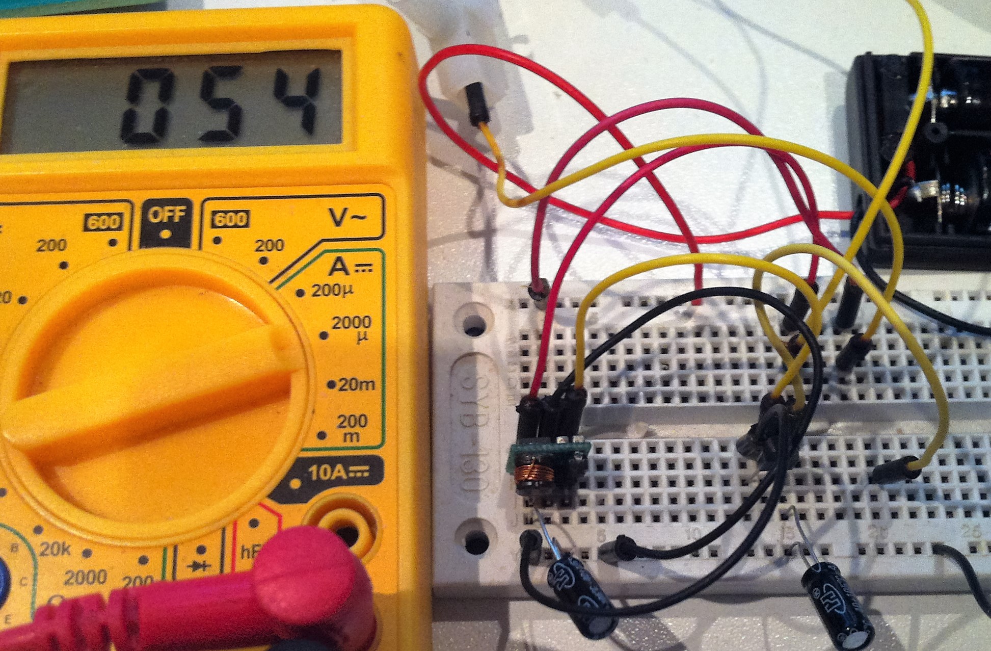
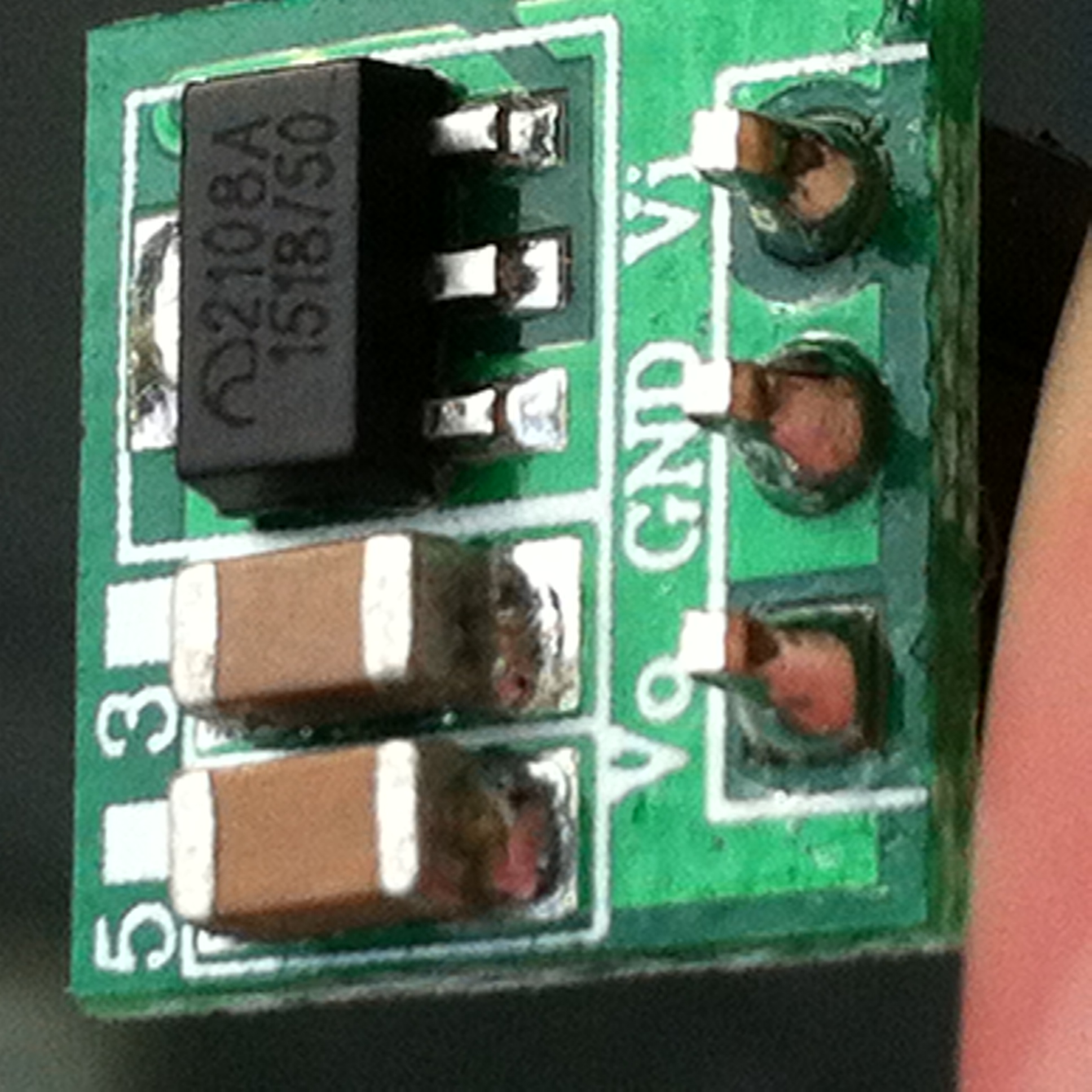
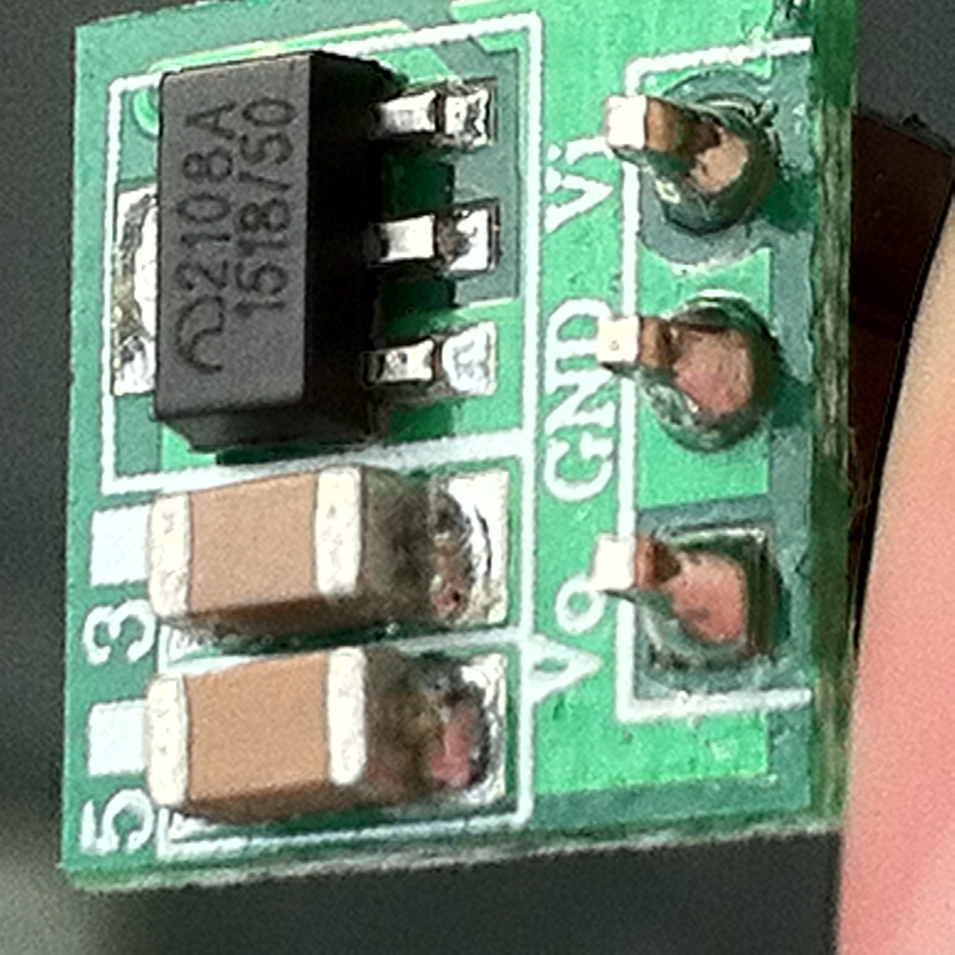
      Just took the time to shoot a pic of my Step-Up consumption, including a Voltage regulator MCP1702-3.3

      As you can see, it's consuming 54uA with nothing connected.

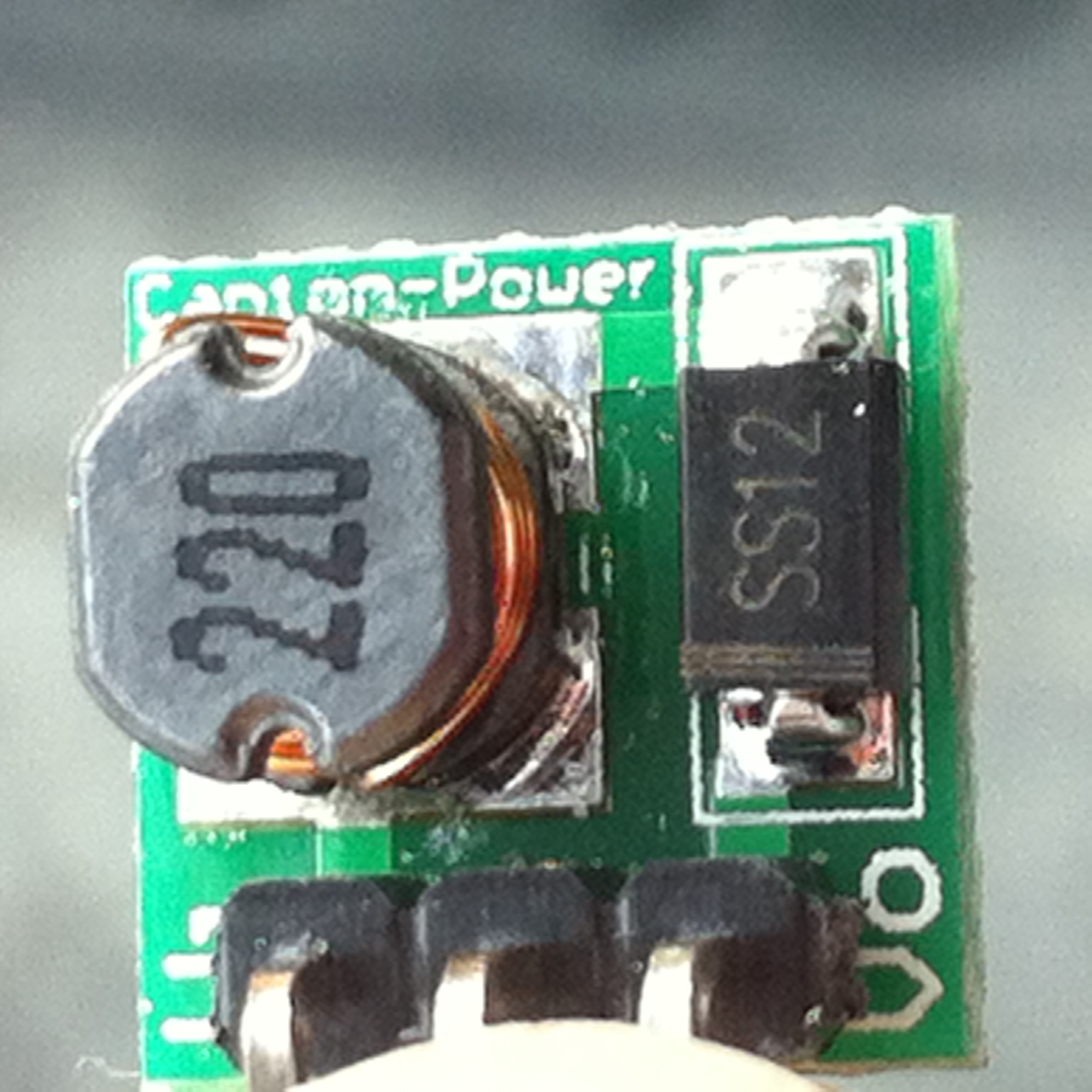
      Step-Up module: link

      The capacitors are really important, one on the input of the step-up module, the other on the output of the MCP1702-3.3, both are 22uF. Without them, consumption is 2.20mA

      IMG_0688 (2).JPG

      rvendrameR Offline
      rvendrameR Offline
      rvendrame
      Hero Member
      wrote on last edited by
      #22

      @ericvdb , do you have any data sheet for this step-up? Or do you know which is the core chip?

      Home Assistant / Vera Plus UI7
      ESP8266 GW + mySensors 2.3.2
      Alexa / Google Home

      1 Reply Last reply
      0
      • E Offline
        E Offline
        ericvdb
        wrote on last edited by
        #23

        No time to look for the datasheet atm, but here are some pics:

        IMG_0695.JPG

        IMG_0696.JPG

        IMG_0697.JPG

        1 Reply Last reply
        0
        • scalzS Offline
          scalzS Offline
          scalz
          Hardware Contributor
          wrote on last edited by scalz
          #24

          Hi.

          maybe it could help some people to "evaluate theoretical" quiescent current...

          if I remember right (I am not in front of my stuff), we can calculate the theoretical power consumption at Input like this:

          I_input = (Vout * I_circuit)/(Vbat * Eff)

          where
          I_input = power consumption at Input
          Vout = booster voltage output
          I_circuit = power consumption of the circuit
          Vbat = battery voltage
          Eff = booster efficiency for Vout and Vbat

          Now, if we take MCP1651, and says we have:

          • a circuit which consumes 50uA (including booster quiescent current, sensors, leakage and a well designed circuit...)
          • a MCP16251 booster with 3.3V output on a single 1.5V cell. Efficiency won't be the same during the whole life. And it is not an ultra high efficiency booster or it it would be named like "ultra high" (when they can, they do advertisement ;) ). This is why we can only see the efficiency at 1mA. But what is efficiency under very light loads (<100uA)? It should need to be tested. no matter, we assume it is like on datasheet.
            So here we have Eff=85% at VIN=1.5V and Eff=80% at 0.9V (near end of life)

          Some maths gives us:
          I_input = (Vout * I_circuit)/(Vbat * Eff)
          I_input = (3.3V * 50uA)/(1.5V * 0.85)
          I_input= 129uA
          So it should use approximatively 129uA at Input/batt.

          Another maths, if batt is at the end of life:
          I_input = (3.3V * 50uA)/(0.9V * 0.80)
          I_input= 229uA

          So here we can see that quiescent current of booster is not always the biggest problem.

          I hope it can help in your choice. And I hope to have not done a mistake lol!

          1 Reply Last reply
          0
          • icebobI Offline
            icebobI Offline
            icebob
            wrote on last edited by
            #25

            @scalz: thank you for you calculation. It's interesting. I will measure it if I receive the MCP16251.

            1 Reply Last reply
            0
            • Adi VacaruA Offline
              Adi VacaruA Offline
              Adi Vacaru
              wrote on last edited by
              #26

              This guy has actually tested the mcp16251 and posted his findings on YouTube https://m.youtube.com/watch?v=O5o6JUjz6Yc

              1 Reply Last reply
              0
              Reply
              • Reply as topic
              Log in to reply
              • Oldest to Newest
              • Newest to Oldest
              • Most Votes


              18

              Online

              11.7k

              Users

              11.2k

              Topics

              113.1k

              Posts


              Copyright 2025 TBD   |   Forum Guidelines   |   Privacy Policy   |   Terms of Service
              • Login

              • Don't have an account? Register

              • Login or register to search.
              • First post
                Last post
              0
              • MySensors
              • OpenHardware.io
              • Categories
              • Recent
              • Tags
              • Popular