In wall light switch node - Custom PCB
-
@Sefi-Ninio - Soon as i get home from work tonight i will get that sorted for you. However i do advise you waiting for revision 3 to come out as currently a new sketch/program can't be uploaded to the uC while the radio is attached.
@samuel235 said:
@Sefi-Ninio - Soon as i get home from work tonight i will get that sorted for you. However i do advise you waiting for revision 3 to come out as currently a new sketch/program can't be uploaded to the uC while the radio is attached.
Thanks!
When do you think rev. 3 will come out and tested? -
Depending on my full-time job workload, I'm hoping to have the designs completed and sent off for manufacturing by sunday, but then we face the 3 week wait for the shipping, and then the testing +/- a week for constant testing measures.
-
Other than re-designing pretty much all of my board to allow for jumpers on the SPI lines that collide with the nRF24 lines, to allow for SPI uploads, how else would you go about this?
The other option would be to run with a 8MHz external crystal to allow my FTDI Serial header to upload sketches. Which if i'm honest, I'de rather not do due to power consumption (If it was a case of using a 16MHz crystal the power consumption would be worth the clock speed increase to get the uC back to sleep quicker, but on wake the uC only have one thing to process then it will go back to sleep anyway, it isn't like it has a lot to process before sleeping again).
-
OK then,
But a thought: if instead of soldering the radio to the PCB, we solder female pins? That way we can easily detach the radio when we want to flush new sketch and attach again. -
OK then,
But a thought: if instead of soldering the radio to the PCB, we solder female pins? That way we can easily detach the radio when we want to flush new sketch and attach again.@Sefi-Ninio - This was a plan of mine right from the start as stated in a few of the early comments. However, to me, this is not an option due to the height restrictions on the board. I really want to keep this as thin as possible to accommodate for various 'new' style switches that take up more than normal ones in terms of the depth of the back box.
I would turn the radio round and stack it on top of the coin-cell but i do not want to be battling with any interference, it will have enough to contend with being nested inside of a metal backbox as it is.
MySensors 2.1.1
Controller - OpenHAB (Virtual Machine)
Gateway - Arduino Mega MQTT Gateway W5100 -
@Sefi-Ninio - This was a plan of mine right from the start as stated in a few of the early comments. However, to me, this is not an option due to the height restrictions on the board. I really want to keep this as thin as possible to accommodate for various 'new' style switches that take up more than normal ones in terms of the depth of the back box.
I would turn the radio round and stack it on top of the coin-cell but i do not want to be battling with any interference, it will have enough to contend with being nested inside of a metal backbox as it is.
@samuel235
While we're on the subject of switches - how is it that you are able to control the switch without a relay on board? -
@samuel235
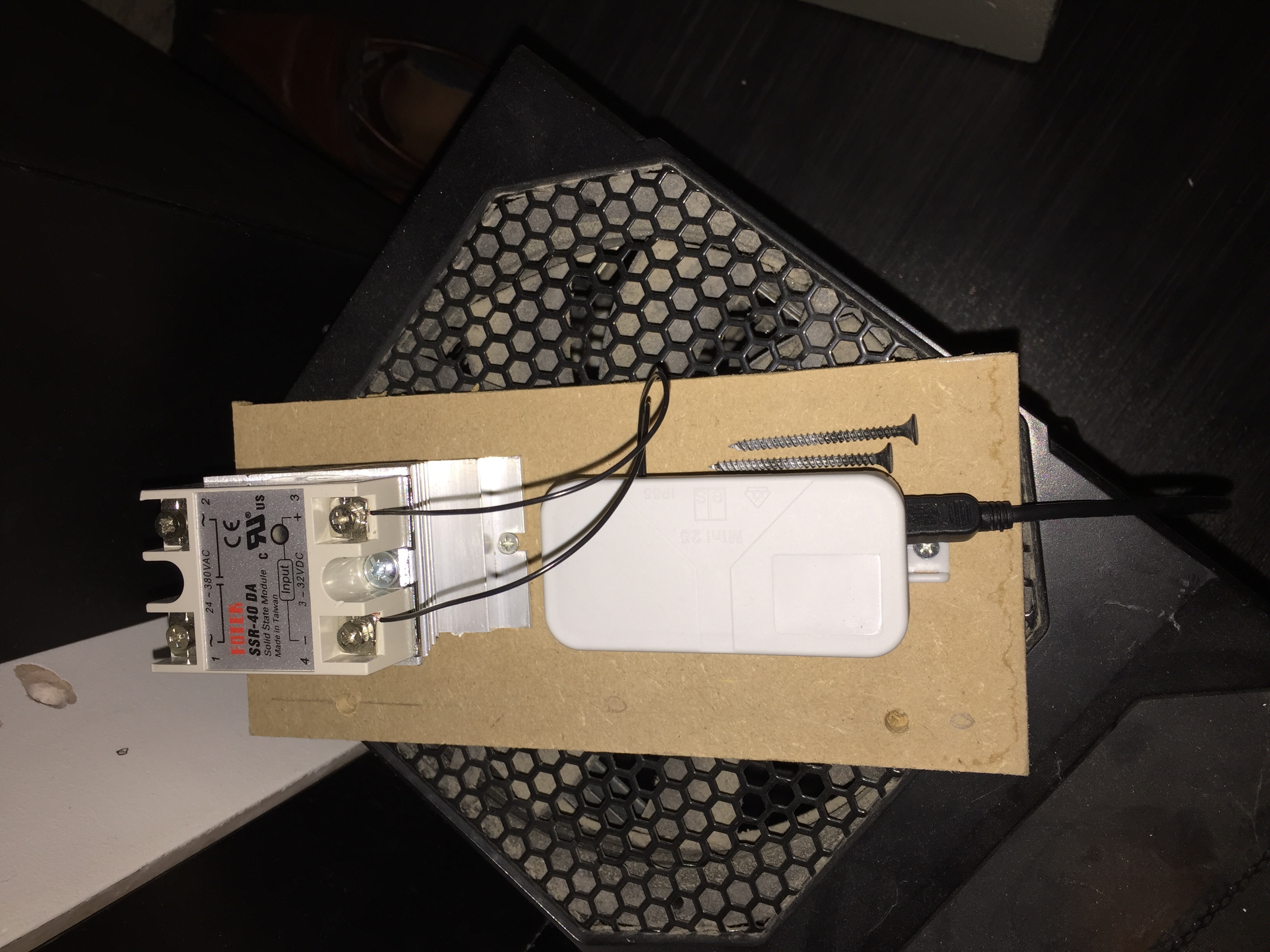
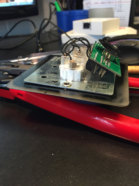
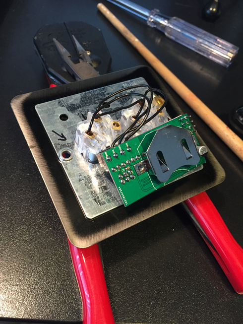
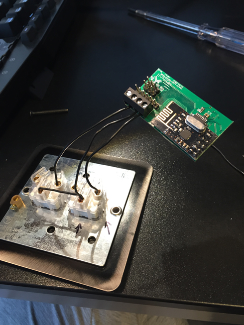
While we're on the subject of switches - how is it that you are able to control the switch without a relay on board?The light switch board itself sends a signal to my controller, that then triggers my other node (relay with button actuator node) to toggle on or off. I've attached a image of my other node that we speak about here that the one side of the relay is connected to my lighting circuit and then i have another switch connected to that node to be able to locally switch the light in case the controller goes down for some unknown reason.
-
So here we have it guys, Revision 2 is now complete, tested and working perfectly! Its been a grueling process but so rewarding. I plan on making a few tiny little changes, including some headers/jumpers to allow ISP uploads while the radio is attached and pull-up resistors to the switch lines. I will get these all ironed out in the next few days and get the designs sent off to get the final boards manufactured. However, I don't feel that there is a great rush for this last board as the upgrades are very minor ones that won't effect its usability right now. The files on the original post are all up to date and relevant including the schematic. I'm yet to test the current draw, I'm trusting that it is sleeping in between the switch toggles, would this be tested via the current draw, if so where should it be measured to confirm this?
Here are a few photographs of the final board attached to a switch plate:
@samuel235 said:
So here we have it guys, Revision 2 is now complete, tested and working perfectly! Its been a grueling process but so rewarding. I plan on making a few tiny little changes, including some headers/jumpers to allow ISP uploads while the radio is attached and pull-up resistors to the switch lines. I will get these all ironed out in the next few days and get the designs sent off to get the final boards manufactured. However, I don't feel that there is a great rush for this last board as the upgrades are very minor ones that won't effect its usability right now. The files on the original post are all up to date and relevant including the schematic. I'm yet to test the current draw, I'm trusting that it is sleeping in between the switch toggles, would this be tested via the current draw, if so where should it be measured to confirm this?
Here are a few photographs of the final board attached to a switch plate:
But here, you show the PCB connected directly to the switch, right?
-
Indeed this is. However I have two switches for this light setup. So, this board is essentially a slave device for the light itself. The relay module that i just posted a picture of is connected to another switch with two length of wire/cable, one connected to GND and the other connected to pin 3. The relay module itself uses the RelayWithButtonActuator sketch, then i can use the local switch and this slave board to control the lighting.
-
OK, so if I get you correctly, the wall switch, when turned on, is detected by the slave module that updates the gateway, which in turn issues a command to the relay module to turn the light on/off. And the slave module detects the switch state change because it makes or breaks the connection.
Correct?That is a smart approach! But for each light you have 2 modules (slave on the switch side and relay on the lamp itself)... That can sum up to a lot of nodes for the entire property...
More so considering a light with 4 way switch (3 different switches that can turn it on/off) - that would require 3 slave modules and a relay module.Also - what are the expectations for battery drain?
@Sefi-Ninio If i understand you correctly, you are correct. However, not every light needs two modules, this has two because i want two switches for this light. For a light that needs only one switch i use the locally connected switch on the relay node itself.
I'll sort out a rough diagram later illustrating this.
MySensors 2.1.1
Controller - OpenHAB (Virtual Machine)
Gateway - Arduino Mega MQTT Gateway W5100 -
@Sefi-Ninio If i understand you correctly, you are correct. However, not every light needs two modules, this has two because i want two switches for this light. For a light that needs only one switch i use the locally connected switch on the relay node itself.
I'll sort out a rough diagram later illustrating this.
@samuel235
Thanks, I'd really appreciate that!Saw you added the gerber files, thanks for that. Could you also provide the BOM file?
a couple more questions, if you don't mind:- Do you know how long the battery is expected to last before it needs to be replaced?
- Does the module support GPIO pins as well, for some sensors to be connected?
Thanks again for taking your time to help!
-
@samuel235
Thanks, I'd really appreciate that!Saw you added the gerber files, thanks for that. Could you also provide the BOM file?
a couple more questions, if you don't mind:- Do you know how long the battery is expected to last before it needs to be replaced?
- Does the module support GPIO pins as well, for some sensors to be connected?
Thanks again for taking your time to help!
@Sefi-Ninio - I will get the BOM uploaded when i get home again. This full-time job really does get in the way of my 'MySensors Life' ahaha. I'm sorry, i forgot to get the BOM last night.
To answer your questions:
-
The only calculations i've done are based on Maniacs workings regarding coin cell powering the uC with an led and rf module. He worked out it should last as long as the battery does, he claimed it used less power than the battery discharge rate. So around 1 year 4 months he calculated. With my current plans for revision 3 having an external 8MHz crystal on board, it should still remain at around that length of time.
-
It doesn't unfortunately since this was designed to be a minimal sized board that fits in the most shallow socket box I work with, i'm a building (plasterer and tiler) by trade and as this is the smallest back box we generally use in the building trade i wanted it to fit in without issues. It was designed to be just a light switch, i did have enitial thoughts to be able to interface the switch with a motion detector and even a temperature sensor to feed back to the controller the temp for the room. But i have a much bigger and more productive module in the design phases at the moment to handle this for each room. I will release another thread based on this new module soon.
-
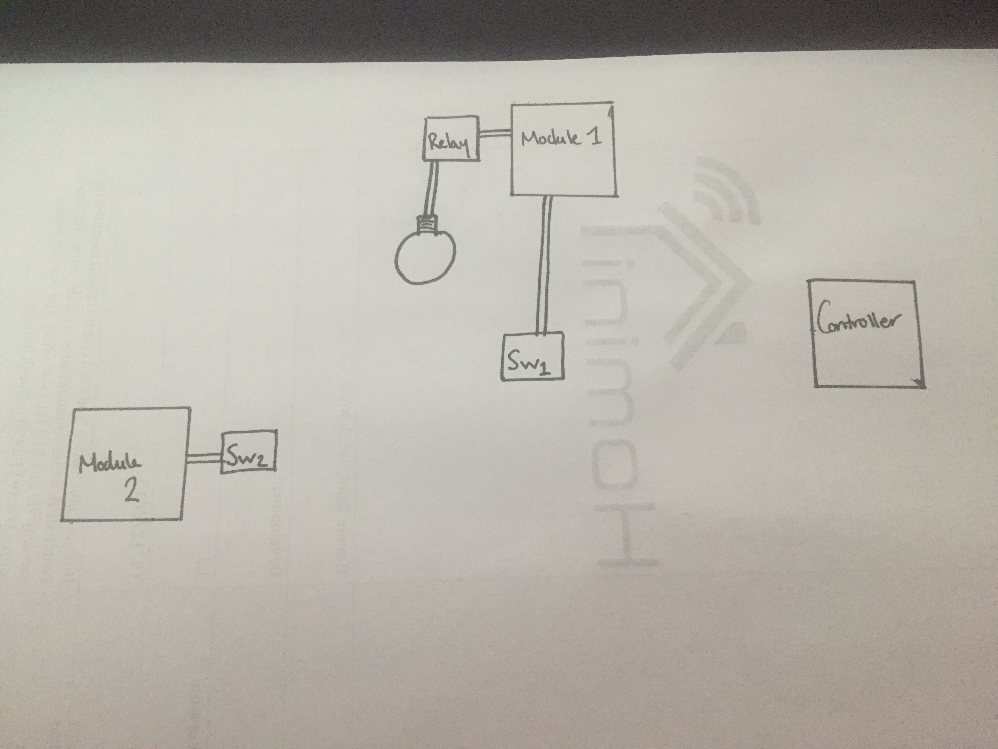
This is my current setup @Sefi-Ninio. The controller is an obvious one for you. Module 1 is currently just an arduino nano connected to a SSR with a NPN transistor (serving as an amp, just to relieve the arduino from harder work than needed to turn the relay). I will at some point have this all on one board, this is designed to be placed in the ceiling close to the light itself. Depending on your needs, this can run either of the MySensors sketches, Relay or RelayWithButtonActuator. I have chose to have mine run the second, so i have a locally connected switch to this module to operate the light from upstairs, this will work whether or not the controller is alive. If you only need one switch and can run a cable/wire, this is your best bet. If not you can either use my board as a 'wireless switch' or as a slave switch for the light.
My board will enable you to control the light module through the controller, however if this controller goes offline, obviously my board will not work. So, if do only need one switch and can run a cable from the light to the switch go with my first example, if you need a secondary switch or even just a case of a wireless switch then go with my board.
-
This is my current setup @Sefi-Ninio. The controller is an obvious one for you. Module 1 is currently just an arduino nano connected to a SSR with a NPN transistor (serving as an amp, just to relieve the arduino from harder work than needed to turn the relay). I will at some point have this all on one board, this is designed to be placed in the ceiling close to the light itself. Depending on your needs, this can run either of the MySensors sketches, Relay or RelayWithButtonActuator. I have chose to have mine run the second, so i have a locally connected switch to this module to operate the light from upstairs, this will work whether or not the controller is alive. If you only need one switch and can run a cable/wire, this is your best bet. If not you can either use my board as a 'wireless switch' or as a slave switch for the light.
My board will enable you to control the light module through the controller, however if this controller goes offline, obviously my board will not work. So, if do only need one switch and can run a cable from the light to the switch go with my first example, if you need a secondary switch or even just a case of a wireless switch then go with my board.
Hello, I'm also very interested about light switch, which is connected to controller, topic. I'm freshman at MySensons comunity, so don't judge me if I have silly questions :)
How You was writting in Your last posts, it is possible to use same PCB like RelayWithButtonActuator sketch. Please corect me if I'm wrong. If I want to control 1 light bulb with 1 button, then I connect solid state relay (SSR) to SW1 and button to SW2.
Questions:- Am I right with this description?
- SSR needs 5VDC input, so in same circuit we would need a step up from 3VDC to 5VDC. But if we were using step up, does 3V battery still have long life (about 1years and 4 months theoricaly)?
Another questions with the look ahead of same project. I think it will be interesting @sundberg84 too.
I was thinking how to put everything in one place with same priorities: safe and small as possible node.
I drew an example:
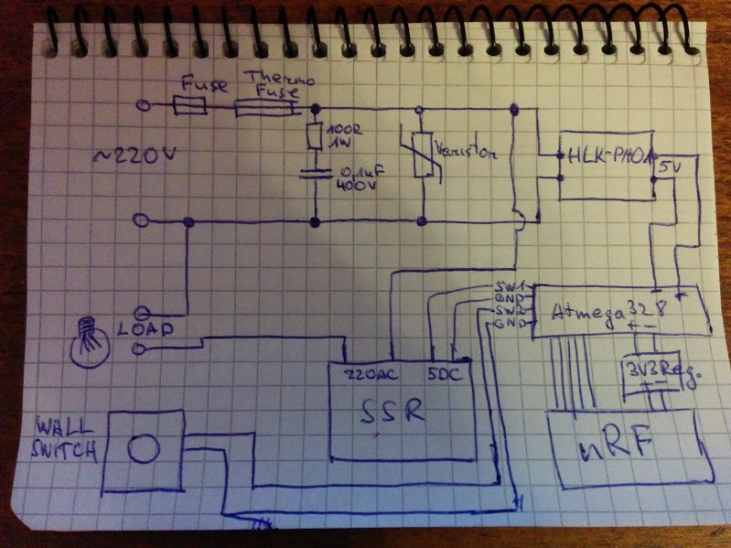
From here I have few questions too:
- I ordered SSR G3MB-202P and in datasheet there was written that it has snubber circuit already. So do I need another snubber circuit near the thermo fuse?
- What would be smarter if we want to make 'universal' PCB for at least 4 switches with buttons: to integrate SSR relays into PCB or make just the connections, like in already made @samuel235 PCB like SW1 and SW2?
Thanks for answers!
-
I'm currently attempting to find a solution to my ISP uploading with the radio attached dilemma.
My initial thought was to have 3 sets of 2pin headers with jumpers on, then remove the jumpers when you need to upload through ISP. But I'm really struggling to do this with the size of the board.
My next thought was to have 3 sets of Surface Mount header pads, then solder them together, then if i needed to use ISP, just de-solder this connection with solder wick, then solder it back together once ISP connection is complete.
The only real need that we would need to upload to this board would be to change the node ID if its set manually (which i do) or to update the sketch with more up to date solutions. The only way around this would be to use a controller such as MysController where you can do OTA uploads, but this would require me to have a crystal on board to allow the use of FTDI to get the bootloader and sketch on in the first place. Am i correct in thinking this, or is there a way to upload just a sketch to the uC through ISP where it allows a bootloader to be present on the uC, as far as i understand when you 'upload using programmer' it uses all of the uC's flash for the program you're loading.
-
Hello, I'm also very interested about light switch, which is connected to controller, topic. I'm freshman at MySensons comunity, so don't judge me if I have silly questions :)
How You was writting in Your last posts, it is possible to use same PCB like RelayWithButtonActuator sketch. Please corect me if I'm wrong. If I want to control 1 light bulb with 1 button, then I connect solid state relay (SSR) to SW1 and button to SW2.
Questions:- Am I right with this description?
- SSR needs 5VDC input, so in same circuit we would need a step up from 3VDC to 5VDC. But if we were using step up, does 3V battery still have long life (about 1years and 4 months theoricaly)?
Another questions with the look ahead of same project. I think it will be interesting @sundberg84 too.
I was thinking how to put everything in one place with same priorities: safe and small as possible node.
I drew an example:
From here I have few questions too:
- I ordered SSR G3MB-202P and in datasheet there was written that it has snubber circuit already. So do I need another snubber circuit near the thermo fuse?
- What would be smarter if we want to make 'universal' PCB for at least 4 switches with buttons: to integrate SSR relays into PCB or make just the connections, like in already made @samuel235 PCB like SW1 and SW2?
Thanks for answers!
Firstly, thank you for showing so much interest!
To answer your questions:
- Yes you're correct, in theory.
- In my relay module i use a NPN transistor to bring the load off of the arduino/uC itself and to create a 'boost' for the SSR to properly register the switch. However, i do use a standard SSR, not a on-board style one. (this is the one i use).
Me and Sundberg have shown interest in each others projects, hopefully soon i will be moving onto a module that will incorporate in-wall powering for itself and its sensors, that i hope to work with @sundberg84 to develop a solution that i have a feeling many of people will like here.
Your next questions:
- I'm not very confident in answering this question right now and i hope that Sundberg will assist you here with that.
- The smart approach (Which i do plan on creating at some point) would be to create a board that has the relays on board along with screw terminals for 4 switches, so one ground and 4 digital input pins. Because these switches will be local to the relays, the board itself wont need to sleep at all, so then this means the only limit on the amount of switch you use are the amount of pins available. Right now my limit of 2 switches is dictated by the amount of interrupt pins we have on board of the ATmega328p-au. If the module sleeps to save energy the only way to have a switch work is to attach it to an interrupt enabled pin, which we only have two of.
There seems to be a slight miss understanding with a few people around here on the duty of this module. This is simply a slave to a relay module because i can not round a cable/wire all the way from the desired location of my relay module, acting as a second switch as i also have a locally connected switch to the relay module, shown in my previous image/sketch.
-
Battery voltage measuring investigations and monitoring methods are now being discussed at http://forum.mysensors.org/topic/3398/another-battery-monitoring-thread/5. This will enable me to have the controller act accordingly when the battery is running low, even have an indicator on the switch itself to let us know when we need to replace the battery before it is too late and we can not use the light switch any more.
Please be sure to add your input on this topic to help us develop this product further.
-
I'm currently researching into capacitive touch sensing. I'm very tempted to create face plates from a 3DPrinter and enable it to have multiple capacitive sensors behind this plate to allow the use as a light switch. This will be an additional option, not necessary for this PCB to work. You will still be able to use a normal switch connected to the PCB. Just would be different software, potentially.
-
Project has been uploaded to https://www.openhardware.io/view/48/Homini-In-Wall-Battery-Powered-Light-Switch-Module
MySensors 2.1.1
Controller - OpenHAB (Virtual Machine)
Gateway - Arduino Mega MQTT Gateway W5100