RELAY 433MHZ + KEYPAD 4x4 COMANDER (vera-domoticz)
-
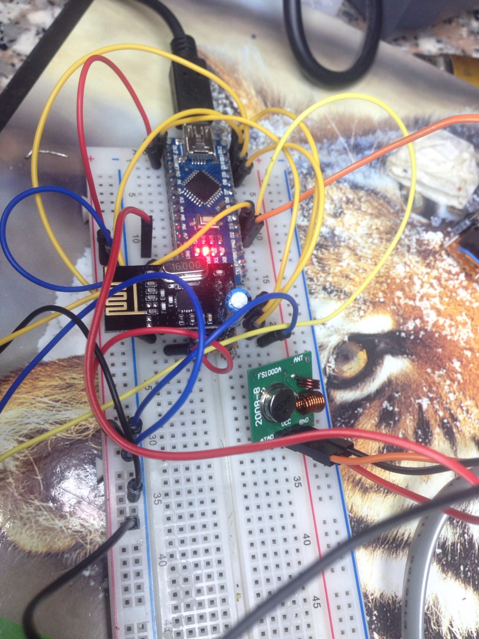
Hello everyone , I'm trying to create a gateway with the following modules ;
433 sender
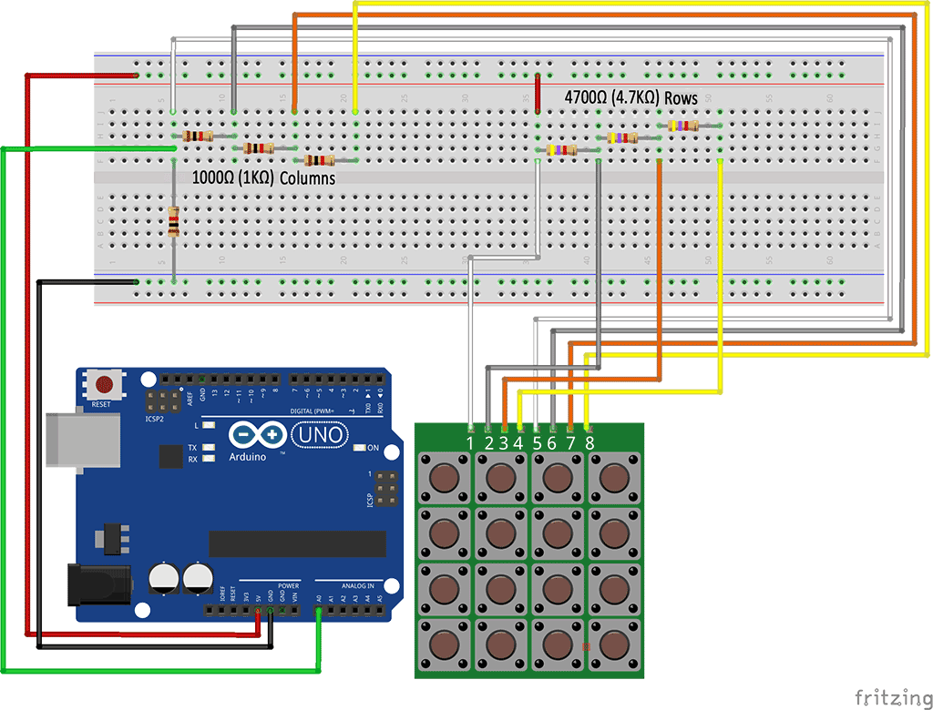
4x4 keypad
Arduino mini / nano
NRF24L01
10uf Capacitorhe project is in development I'm stuck in the insertion of the keypad would use 4 -pin analog and 4 digital pins . I welcome suggestions on code.
link where it started my idea: http://forum.mysensors.org/topic/1557/combined-mysensor-gateway-with-433mhz-transmitter-homeeasy-klik-aan-klik-uit
link original code which I then edited: https://github.com/meijeren/MySensors-RF433-Node
https://codebender.cc/sketch:209936
-
@Michel-It There is an Adruino module for scanning 4x4 key matrixs. You can find it here: http://playground.arduino.cc/Main/KeypadTutorial
-
I have one better, but how to implement it in code mysensor?

.
New Code > sketch + Library > https://codebender.cc/sketch:183503
Original Code
#include <MyTransportNRF24.h>
#include <MyHwATMega328.h>
#include <MySensor.h>
#include <SPI.h>
#include <Wire.h>
#include <RCSwitch.h>
RCSwitch mySwitch = RCSwitch();

#define NODE_ID          165
#define NODE_VERSION     "1.1"
#define NODE_DESCRIPTION "MikRelay"


#define NUMFLAKES 10
#define XPOS 0
#define YPOS 1
#define DELTAY 2

#define RADIO_TX_PIN 2
#define NUMBER_OF_RELAYS 11 // Total number of attached relays
typedef struct
{
  unsigned long address;
  unsigned char unit;
  bool dimmer;
} MikParams;
MikParams Mik_PARAMS[NUMBER_OF_RELAYS] =
{
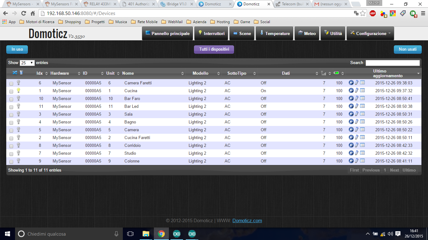
  {87311, 24, false},
  {87500, 24, false},
  {87491, 24, false},
  {87359, 24, false},
  {87539, 24, false},
  {87548, 24, false},
  {87536, 24, false},
  {87356, 24, false},
  {87503, 24, false},
  {4011779, 24, false},
  {4011968, 24, false}

};


// NRFRF24L01 radio driver (set low transmit power by default)
MyTransportNRF24 radio(RF24_CE_PIN, RF24_CS_PIN, RF24_PA_LEVEL_GW);
//MyTransportRFM69 radio;
// Message signing driver (none default)
//MySigningNone signer;
// Select AtMega328 hardware profile
MyHwATMega328 hw;
// Construct MySensors library
MySensor gw(radio, hw);

void setup()
{
  mySwitch.enableTransmit(RADIO_TX_PIN);
  // init done
  // Show image buffer on the display hardware.
  // Since the buffer is intialized with an Adafruit splashscreen
  // internally, this will display the splashscreen.
  // Initialize library and add callback for incoming messages
  gw.begin(incomingMessage, NODE_ID, false);

  delay(2000);

  // Send the sketch version information to the gateway and Controller
  gw.sendSketchInfo(NODE_DESCRIPTION, NODE_VERSION);

  // Fetch relay status
  for (int sensor = 1; sensor <= NUMBER_OF_RELAYS; sensor++) {
    // Register all sensors to gw (they will be created as child devices)
    gw.present(sensor, S_LIGHT);
  }
}

void loop()
{
  // Alway process incoming messages whenever possible
  gw.process();
}

void incomingMessage(const MyMessage &message)
{
  if ((message.sensor < 1) && (message.sensor >= NUMBER_OF_RELAYS))
  {
    return;
  }
  if (message.type == V_LIGHT)
  {
    mySwitch.send(Mik_PARAMS[message.sensor - 1].address, Mik_PARAMS[message.sensor - 1].unit);
    // Store state in eeprom
    gw.saveState(message.sensor, message.getBool());
    // Write some debug info
    Serial.print("Incoming change for sensor:");
    Serial.print(message.sensor);
    Serial.print(", Miks: ");
    Serial.print(Mik_PARAMS[message.sensor - 1].address);
    Serial.print(", Miks: ");
    Serial.print(Mik_PARAMS[message.sensor - 1].unit);
    Serial.print(", New status: ");
    Serial.println(message.getBool());

  }
  else if (message.type == V_DIMMER)
  {
    mySwitch.send(Mik_PARAMS[message.sensor - 1].address, Mik_PARAMS[message.sensor - 1].unit);
  }
}```
I know that not everyone. but there is some kind soul can help me?
I see you do not laugh!
