Skip to content
  • MySensors
  • OpenHardware.io
  • Categories
  • Recent
  • Tags
  • Popular
Skins
  • Light
  • Brite
  • Cerulean
  • Cosmo
  • Flatly
  • Journal
  • Litera
  • Lumen
  • Lux
  • Materia
  • Minty
  • Morph
  • Pulse
  • Sandstone
  • Simplex
  • Sketchy
  • Spacelab
  • United
  • Yeti
  • Zephyr
  • Dark
  • Cyborg
  • Darkly
  • Quartz
  • Slate
  • Solar
  • Superhero
  • Vapor

  • Default (No Skin)
  • No Skin
Collapse
Brand Logo
  1. Home
  2. Hardware
  3. Rechargeable Lithium Ion Sensor Custom PCB

Rechargeable Lithium Ion Sensor Custom PCB

Scheduled Pinned Locked Moved Hardware
71 Posts 12 Posters 29.4k Views 8 Watching
  • Oldest to Newest
  • Newest to Oldest
  • Most Votes
Reply
  • Reply as topic
Log in to reply
This topic has been deleted. Only users with topic management privileges can see it.
  • akumarA akumar

    So if I sum up, powering this node with a single Lipo cell will work by connecting the Lipo to the raw pin on the arduino. This will work from 4.2v to 3.4v. This is not that good for the battery life.
    Using 2*AA batteries with a boost converter seems a lot easier...
    I'm almost giving up on this idea : I liked the flat form factor of the lipos and they were solar pannel friendly. Is there a way to use a voltage regulator from 4.2v to 3.4v and then switch the circuit to a boost converter from 3.3v to 2.8v ?

    F Offline
    F Offline
    flopp
    wrote on last edited by
    #28

    @akumar
    You shall not go below 3,0v on a Lipo, it will/can get damage

    1 Reply Last reply
    0
    • akumarA Offline
      akumarA Offline
      akumar
      wrote on last edited by
      #29

      Looking at discharge curves I can see that I should be able to squeeze 75% of the battery capacity if I charge it back when it reaches 3.3v. On a low power node this could work.
      @flopp The reason I was mentionning 2.8v is because the battery protection module will kick in at this voltage. But you're right, no reason to go this far.

      Thanks !

      F 1 Reply Last reply
      0
      • akumarA akumar

        Looking at discharge curves I can see that I should be able to squeeze 75% of the battery capacity if I charge it back when it reaches 3.3v. On a low power node this could work.
        @flopp The reason I was mentionning 2.8v is because the battery protection module will kick in at this voltage. But you're right, no reason to go this far.

        Thanks !

        F Offline
        F Offline
        flopp
        wrote on last edited by
        #30

        @akumar
        That battery protection is built-in on battery, but must take it with care. There as some cheap LiPo that doesn't have that feature.
        I don't think the TP4056 have protection or does it?

        1 Reply Last reply
        0
        • akumarA Offline
          akumarA Offline
          akumar
          wrote on last edited by
          #31

          Sure ! The newer ones have a battery protection chip. I've tested it and it kicks in at 2.8v.
          http://www.aliexpress.com/item/Free-Shipping-10pcs-lot-1a-lithium-battery-charging-18650-with-protection-one-plate-protec-2-in/1876166772.html

          1 Reply Last reply
          0
          • F Offline
            F Offline
            flopp
            wrote on last edited by
            #32

            Now I see, there are pads for battery and pads for out. Looks good

            HenryWhiteH 1 Reply Last reply
            0
            • F flopp

              Now I see, there are pads for battery and pads for out. Looks good

              HenryWhiteH Offline
              HenryWhiteH Offline
              HenryWhite
              wrote on last edited by HenryWhite
              #33

              @flopp said:

              Now I see, there are pads for battery and pads for out. Looks good

              Correct. The old Tp4056 modules do not have the OUT terminals (and therefore won't fit on the pcb I designed in this thread)

              @akumar said:

              On a low power node this could work.

              Why should it only work on a low power node?

              1 Reply Last reply
              0
              • scalzS Offline
                scalzS Offline
                scalz
                Hardware Contributor
                wrote on last edited by scalz
                #34

                hi.

                "Why should it only work on a low power node?"

                with time we will have more and more things to charge every week/day (phone, watch, iot...), so I would say : for less maintenance ? lol

                more seriously, it is a nice project I will follow it ;) I have one board to order (not ordered yet) with a li charger but mine is definitely not diy (too small chip so it is for stencil use).
                Mobile phone batt is a very nice idea :smiley: I am a more confident than cheap lipo..and I have some old cheap galaxy s2 batt..How do you plan to hook the battery to your board?

                HenryWhiteH 1 Reply Last reply
                0
                • scalzS scalz

                  hi.

                  "Why should it only work on a low power node?"

                  with time we will have more and more things to charge every week/day (phone, watch, iot...), so I would say : for less maintenance ? lol

                  more seriously, it is a nice project I will follow it ;) I have one board to order (not ordered yet) with a li charger but mine is definitely not diy (too small chip so it is for stencil use).
                  Mobile phone batt is a very nice idea :smiley: I am a more confident than cheap lipo..and I have some old cheap galaxy s2 batt..How do you plan to hook the battery to your board?

                  HenryWhiteH Offline
                  HenryWhiteH Offline
                  HenryWhite
                  wrote on last edited by HenryWhite
                  #35

                  @scalz said:

                  How do you plan to hook the battery to your board?

                  As smartphone batteries are usually fully enclosed, I will just stick the battery (I will use the galaxy s4 batteries) under the pcb.

                  The whole package should fit nicely in a 75x75x40 distribution box, which will only cost a few cents in your local hardware store.
                  Only downside of the boxes is that they are a bit ugly :D
                  But since I don't have a 3D printer yet i will go with that solution and maybe paint the boxes black or white.

                  1 Reply Last reply
                  0
                  • scalzS Offline
                    scalzS Offline
                    scalz
                    Hardware Contributor
                    wrote on last edited by
                    #36

                    cool.
                    I am building my 3d printer actually because I want custom things (not too much ugly) ;)
                    I was talking about how to wire between the batt and the board. So you will solder wire on it?
                    but it is not a big a problem I think, if I use these sort of batt, maybe I will try to find some contacts and handle this in the custom box.

                    see you soon :)

                    HenryWhiteH 1 Reply Last reply
                    0
                    • scalzS scalz

                      cool.
                      I am building my 3d printer actually because I want custom things (not too much ugly) ;)
                      I was talking about how to wire between the batt and the board. So you will solder wire on it?
                      but it is not a big a problem I think, if I use these sort of batt, maybe I will try to find some contacts and handle this in the custom box.

                      see you soon :)

                      HenryWhiteH Offline
                      HenryWhiteH Offline
                      HenryWhite
                      wrote on last edited by HenryWhite
                      #37

                      @scalz said:

                      I am building my 3d printer actually because I want custom things (not too much ugly) ;)

                      I thought about that too, but then I saw how much calibration, try&error etc. you need to assemble your own 3D printer. And after that it's still a hassle to get prints with good quality.
                      Because of that I will just save money for the ultimaker 2.. :D

                      @scalz said:

                      I was talking about how to wire between the batt and the board. So you will solder wire on it?

                      Yes, I will solder the contacts of the battery directly to the tp4056 module. Because you don't have to replace the battery (until it breaks) this method should be fine.

                      1 Reply Last reply
                      0
                      • scalzS Offline
                        scalzS Offline
                        scalz
                        Hardware Contributor
                        wrote on last edited by
                        #38

                        :+1: it makes sense too.

                        1 Reply Last reply
                        0
                        • scalzS Offline
                          scalzS Offline
                          scalz
                          Hardware Contributor
                          wrote on last edited by scalz
                          #39

                          "Because of that I will just save money for the ultimaker 2"

                          yep but calibration, try&errors, settings.. are always there, even if you have a 2000 dollars printers. no plug and play, it is some kind of myth for the moment that people don't know before buy one. but lot of people are working to improve commercial or diy printer.
                          For instance, I did some orders on 3dhub. Some were printed with prusa or ultimaker, pla or abs... And sometimes I got better quality from a prusa owner than ultimaker owner. One box was dark burnt on ultimaker, it was not good. So it is a matter to well know the stuff ;)
                          and then it is very proprietary (filament, settings, software...).
                          I have talked about this with some fablabs people who have expensive printer (ultimaker, zortrax for instance) and diy corexy printer. That is why I am building my corexy which cost to me 300€ and I know every angle of it ;). Some learning curve, which expensive printer have too, but then no more proprietary&co problem..just my point of view...

                          1 Reply Last reply
                          0
                          • H Offline
                            H Offline
                            Heizelmann
                            wrote on last edited by
                            #40

                            If the module also should be operated while charging and the DHT11 sits directly on the board close to the battery charger the sensor would show significantly higher temperatures caused by the TP4056 battery charger which becomes really hot during charging.

                            On an experiment on a breadboard with comparable distance I measured a temperature of the TP4056 of about 70 degree Celsius in the first phase of charging and the sensor reading rises from about 20 to 22 degrees.

                            HenryWhiteH 1 Reply Last reply
                            0
                            • H Heizelmann

                              If the module also should be operated while charging and the DHT11 sits directly on the board close to the battery charger the sensor would show significantly higher temperatures caused by the TP4056 battery charger which becomes really hot during charging.

                              On an experiment on a breadboard with comparable distance I measured a temperature of the TP4056 of about 70 degree Celsius in the first phase of charging and the sensor reading rises from about 20 to 22 degrees.

                              HenryWhiteH Offline
                              HenryWhiteH Offline
                              HenryWhite
                              wrote on last edited by HenryWhite
                              #41

                              @Heizelmann you're right, the module gets pretty warm.
                              Here I found some more measurements for the Tp4056: http://lygte-info.dk/review/Review Charger TP4056 UK.html

                              Although the board is designed to bend the DHT22 over the prototyping area so that it is horizontal and not vertical aligned, I think I could swap positions of the prototyping area and the mounting point for the DHT22.

                              To keep the Tp4056 cooler, you could add a small heatsink to it or replace the resistor so that it charges with lower current.

                              1 Reply Last reply
                              0
                              • akumarA akumar

                                So if I sum up, powering this node with a single Lipo cell will work by connecting the Lipo to the raw pin on the arduino. This will work from 4.2v to 3.4v. This is not that good for the battery life.
                                Using 2*AA batteries with a boost converter seems a lot easier...
                                I'm almost giving up on this idea : I liked the flat form factor of the lipos and they were solar pannel friendly. Is there a way to use a voltage regulator from 4.2v to 3.4v and then switch the circuit to a boost converter from 3.3v to 2.8v ?

                                F Offline
                                F Offline
                                flopp
                                wrote on last edited by flopp
                                #42

                                @akumar said:

                                So if I sum up, powering this node with a single Lipo cell will work by connecting the Lipo to the raw pin on the arduino. This will work from 4.2v to 3.4v. This is not that good for the battery life.
                                Using 2*AA batteries with a boost converter seems a lot easier...
                                I'm almost giving up on this idea : I liked the flat form factor of the lipos and they were solar pannel friendly. Is there a way to use a voltage regulator from 4.2v to 3.4v and then switch the circuit to a boost converter from 3.3v to 2.8v ?

                                Maybe this can be used. But I use 0.1mA when "sleeping"
                                https://www.pololu.com/product/2122

                                1 Reply Last reply
                                0
                                • F Offline
                                  F Offline
                                  flopp
                                  wrote on last edited by
                                  #43

                                  http://www.aliexpress.com/item/10pcs-2-in-1-Tinysine-Charge-Pump-Step-Down-Step-Up-Boost-Buck-2-5V-3V/32366514629.html?spm=2114.01020208.3.1.FuE3W9&ws_ab_test=searchweb201556_2,searchweb201644_2_10001_10002_10005_10006_10003_10004_62,searchweb201560_2,searchweb1451318400_6148

                                  1 Reply Last reply
                                  0
                                  • akumarA Offline
                                    akumarA Offline
                                    akumar
                                    wrote on last edited by
                                    #44

                                    @flopp : cool module ! This could do the trick. The 0.1 mA could be taken care of by powering the module via a MOSFET controlled by the arduino. It would then power the sensors and the radio only when needed.

                                    1 Reply Last reply
                                    0
                                    • HenryWhiteH Offline
                                      HenryWhiteH Offline
                                      HenryWhite
                                      wrote on last edited by
                                      #45

                                      Again, to prove my point that you don't need to go below 3.3V (at least with modern smartphone batteries), I just measured my Galaxy S5's battery at 4% battery state. The measured voltage is 3.65V.

                                      F 1 Reply Last reply
                                      0
                                      • HenryWhiteH HenryWhite

                                        Again, to prove my point that you don't need to go below 3.3V (at least with modern smartphone batteries), I just measured my Galaxy S5's battery at 4% battery state. The measured voltage is 3.65V.

                                        F Offline
                                        F Offline
                                        flopp
                                        wrote on last edited by
                                        #46

                                        @HenryWhite
                                        Wow, what are your low/max limit?

                                        4% seems to be very low if your low limit is 3.3.

                                        HenryWhiteH 1 Reply Last reply
                                        0
                                        • F flopp

                                          @HenryWhite
                                          Wow, what are your low/max limit?

                                          4% seems to be very low if your low limit is 3.3.

                                          HenryWhiteH Offline
                                          HenryWhiteH Offline
                                          HenryWhite
                                          wrote on last edited by HenryWhite
                                          #47

                                          @flopp said:

                                          @HenryWhite
                                          Wow, what are your low/max limit?

                                          I must admit i didn't understand that :smile:

                                          At 2% battery state (according to what is shown in the android UI) the s5 battery still outputs 3.43V (measured with multimeter and compared to android app "Ampere")
                                          Even at 1% the voltage is still above 3.3V:
                                          2016-01-13 19_17_14-Screenshot_2016-01-13-19-10-52.png

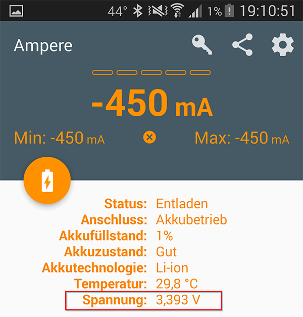
                                          But: I just discovered that the galaxy s5's battery is a 3.85V li-ion battery with a charging voltage of 4.4V instead of 4.2V..

                                          But even then, the 3.8V S4 battery which I'm going to use for my sensors will approximately reach less than 3.3V not before the battery is under 5% charging state I think.

                                          1 Reply Last reply
                                          0
                                          Reply
                                          • Reply as topic
                                          Log in to reply
                                          • Oldest to Newest
                                          • Newest to Oldest
                                          • Most Votes


                                          24

                                          Online

                                          11.7k

                                          Users

                                          11.2k

                                          Topics

                                          113.1k

                                          Posts


                                          Copyright 2025 TBD   |   Forum Guidelines   |   Privacy Policy   |   Terms of Service
                                          • Login

                                          • Don't have an account? Register

                                          • Login or register to search.
                                          • First post
                                            Last post
                                          0
                                          • MySensors
                                          • OpenHardware.io
                                          • Categories
                                          • Recent
                                          • Tags
                                          • Popular