INA219 DC Current Sensor
-
Thanks !
-
has anyone made something usefull with the ACS712 yet ?
-
I am using a two way switch to control my device. The idea is to control the state from arduino as well as physical switch parallely.
Physical switch ON, Arduino can switch it OFF
Arduino switches it ON, Physical switch whatever be the state on push should switch it OFF.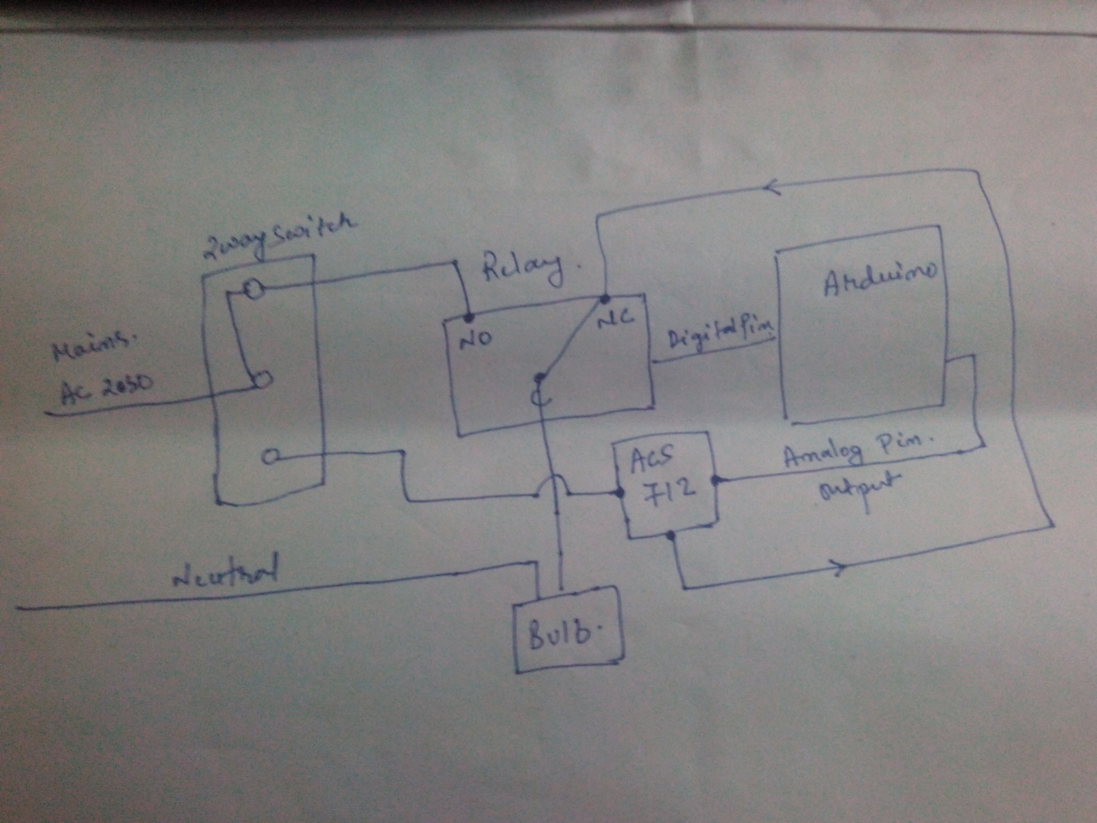
I have used the Relay actuator example code from mysensor and little more code which I found in arduino forum.
I am not able to use the plugin to embed the code, anyways the following is the code.
// Example sketch showing how to control physical relays.
// This example will remember relay state even after power failure.#include <MySensor.h>
#include <SPI.h>#define RELAY_1 2 // Arduino Digital I/O pin number for first relay (second on pin+1 etc)
#define RELAY_2 3
#define NUMBER_OF_RELAYS 2 // Total number of attached relays
#define RELAY_ON 1 // GPIO value to write to turn on attached relay
#define RELAY_OFF 0 // GPIO value to write to turn off attached relay
#define CHILD_ID 1#define CURRENT_SENSOR A0 // Analog input pin that sensor is attached to
MyMessage msg(CHILD_ID, V_TRIPPED); //Using this as the message to report the physical switch on statusfloat amplitude_current; //amplitude current
float effective_value;
bool switch_1_on;
int count = 0;
MySensor gw;void setup()
{
// Initialize library and add callback for incoming messages
gw.begin(incomingMessage, 21, true);// Send the sketch version information to the gateway and Controller
gw.sendSketchInfo("Relay with current sensor", "1.0");
pins_init();// Fetch relay status
for (int sensor=1, pin=RELAY_1; sensor<=NUMBER_OF_RELAYS;sensor++, pin++) {
// Register all sensors to gw (they will be created as child devices)
gw.present(sensor, S_LIGHT);
// Then set relay pins in output mode
pinMode(pin, OUTPUT);
// Set relay to last known state (using eeprom storage)
digitalWrite(pin, gw.loadState(sensor)?RELAY_ON:RELAY_OFF);
}
}void loop()
{
int sensor_max;
sensor_max = getMaxValue();
Serial.print("sensor_max = ");
Serial.println(sensor_max);
//the VCC on the Grove interface of the sensor is 5v
amplitude_current=(float)(sensor_max-512)/10245/1851000000;
effective_value=amplitude_current/1.414;
//minimum_current=1/10245/1851000000/1.414=18.7(mA)
//Only for sinusoidal alternating current
Serial.println("The amplitude of the current is(in mA)");
Serial.println(amplitude_current,1);//Only one number after the decimal point
Serial.println("The effective value of the current is(in mA)");
Serial.println(effective_value,1);if (count == 0 && amplitude_current > 30) { switch_1_on = true; Serial.println("physical switch on"); gw.send(msg.set(switch_1_on?"1":"0")); count = 1 ; } else { count = 0 ; }// Alway process incoming messages whenever possible
gw.process();
}void incomingMessage(const MyMessage &message) {
// We only expect one type of message from controller. But we better check anyway.
if (message.type == V_FAN) {
Serial.println("Message arrived for FAN");
Serial.println(message.sensor);
for(int i=4 ; i<=7; i++) {
digitalWrite(i,0);
}
}
if (message.type==V_LIGHT) {
// Change relay state
digitalWrite(message.sensor-1+RELAY_1, message.getBool()?RELAY_ON:RELAY_OFF);
// Store state in eeprom
gw.saveState(message.sensor, message.getBool());
// Write some debug info
Serial.print("Incoming change for sensor:");
Serial.print(message.sensor);
Serial.print(", New status: ");
Serial.println(message.getBool());
}
}void pins_init()
{
pinMode(CURRENT_SENSOR, INPUT);
}
/Function: Sample for 1000ms and get the maximum value from the S pin/
int getMaxValue()
{
int sensorValue; //value read from the sensor
int sensorMax = 0;
uint32_t start_time = millis();
while((millis()-start_time) < 1000)//sample for 1000ms
{
sensorValue = analogRead(CURRENT_SENSOR);
if (sensorValue > sensorMax)
{
/record the maximum sensor value/
sensorMax = sensorValue;
}
}
return sensorMax;
}@mainali said in INA219 DC Current Sensor:
MySensor gw;
I am building similar system. However, i am facing a lot of difficulties to make the ACS712 working. I have tried your code as well without success. The effective value of the current is always 0 mA even if the light is ON.
For the moment, i am testing with 5V current and i switch on a LED. maybe the current is too low to make working my 20A ACS712?
If anyone has some ideas, it will be very greatful :) Thanks a lot.