Need help with Relay 1.0 Actuator
-
Hi everyone,
I could really use your help with an Relay Actuator built. Just to let you all know I'm a newbie at this. To give an idea where I'm at with my home automation sensor projects. I'm building them and adding them to my Vera-Lite controller. I have already built my gateway "Ethernet", one motion detector, one humidity/Temp sensor, one Temp sensor with five temp sensors, and one single relay actuator and they all work great. The Problem I ran into is on my second relay actuator build. It is a 8 relay set. First off I couldn't figure out how to set the A0 & A1 pins. So for testing purposes I only utilized 6 of them, until I could figure out to modify the sketch to operate the last two. The big issue I ran into is when I went to test it. It registered itself as a 0 node, same as my gateway. All 6, of the relays I wired up, showed up and were registered as 0;1-6. However they will not responded.
My Question is: is there away to assign a node to a senor build? All my other sensors are assigned nodes 2-5 as I included them in the gateway.
This is what I receive from the, debug, serial monitor. I'm also using MYSController program so I can see which sensor is assigned to which node.
send: 0-0-0-0 s=255,c=3,t=15,pt=2,l=2,sg=0,st=fail:0
send: 0-0-0-0 s=255,c=0,t=18,pt=0,l=5,sg=0,st=fail:1.5.4
send: 0-0-0-0 s=255,c=3,t=6,pt=1,l=1,sg=0,st=fail:0
repeater started, id=0, parent=0, distance=0
send: 0-0-0-0 s=255,c=3,t=11,pt=0,l=6,sg=0,st=fail:Relay6
send: 0-0-0-0 s=255,c=3,t=12,pt=0,l=3,sg=0,st=fail:1.0
send: 0-0-0-0 s=1,c=0,t=3,pt=0,l=0,sg=0,st=fail:
find parent
send: 0-0-255-255 s=255,c=3,t=7,pt=0,l=0,sg=0,st=bc:
send: 0-0-0-0 s=2,c=0,t=3,pt=0,l=0,sg=0,st=fail:
send: 0-0-0-0 s=3,c=0,t=3,pt=0,l=0,sg=0,st=fail:
send: 0-0-0-0 s=4,c=0,t=3,pt=0,l=0,sg=0,st=fail:
send: 0-0-0-0 s=5,c=0,t=3,pt=0,l=0,sg=0,st=fail:
send: 0-0-0-0 s=6,c=0,t=3,pt=0,l=0,sg=0,st=fail: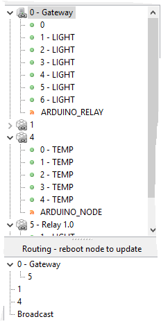
Any help would be greatly appreciated!
-
Hi everyone,
I could really use your help with an Relay Actuator built. Just to let you all know I'm a newbie at this. To give an idea where I'm at with my home automation sensor projects. I'm building them and adding them to my Vera-Lite controller. I have already built my gateway "Ethernet", one motion detector, one humidity/Temp sensor, one Temp sensor with five temp sensors, and one single relay actuator and they all work great. The Problem I ran into is on my second relay actuator build. It is a 8 relay set. First off I couldn't figure out how to set the A0 & A1 pins. So for testing purposes I only utilized 6 of them, until I could figure out to modify the sketch to operate the last two. The big issue I ran into is when I went to test it. It registered itself as a 0 node, same as my gateway. All 6, of the relays I wired up, showed up and were registered as 0;1-6. However they will not responded.
My Question is: is there away to assign a node to a senor build? All my other sensors are assigned nodes 2-5 as I included them in the gateway.
This is what I receive from the, debug, serial monitor. I'm also using MYSController program so I can see which sensor is assigned to which node.
send: 0-0-0-0 s=255,c=3,t=15,pt=2,l=2,sg=0,st=fail:0
send: 0-0-0-0 s=255,c=0,t=18,pt=0,l=5,sg=0,st=fail:1.5.4
send: 0-0-0-0 s=255,c=3,t=6,pt=1,l=1,sg=0,st=fail:0
repeater started, id=0, parent=0, distance=0
send: 0-0-0-0 s=255,c=3,t=11,pt=0,l=6,sg=0,st=fail:Relay6
send: 0-0-0-0 s=255,c=3,t=12,pt=0,l=3,sg=0,st=fail:1.0
send: 0-0-0-0 s=1,c=0,t=3,pt=0,l=0,sg=0,st=fail:
find parent
send: 0-0-255-255 s=255,c=3,t=7,pt=0,l=0,sg=0,st=bc:
send: 0-0-0-0 s=2,c=0,t=3,pt=0,l=0,sg=0,st=fail:
send: 0-0-0-0 s=3,c=0,t=3,pt=0,l=0,sg=0,st=fail:
send: 0-0-0-0 s=4,c=0,t=3,pt=0,l=0,sg=0,st=fail:
send: 0-0-0-0 s=5,c=0,t=3,pt=0,l=0,sg=0,st=fail:
send: 0-0-0-0 s=6,c=0,t=3,pt=0,l=0,sg=0,st=fail:Any help would be greatly appreciated!
@Donny152 said:
My Question is: is there away to assign a node to a senor build?
No problems, In 1.5 you use
gw.begin(incomingMessage, 6)Where in this case 6 means NodeID6.
If you use the standard relay sketch you see this: gw.begin(incomingMessage, AUTO, true); where you change Auto to your ID if choise.The debug monitor looks like you have power or range issues (ST:FAIL)
"st=fail" means the receiving node or gateway has problems sending ack back to the sending node.Its probably a hardware issue (power and/or range). Try adding a capacitor (http://www.mysensors.org/build/connect_radio#connecting-a-decoupling-capacitor) to the receiving radio, change powersource, move receiver/sender closer to eachother or build a repeater.
These two problems are probably connected. Since the node cant reach/talk to the gateway correctly thats why you have 0 as node id. Correct the st=fail issue and I think everything will run smother.
In relay nodes, my experience is that its almost always the power supply.
-
Thank you! That worked perfectly. I have a 10uF capacitor on there now and it only 2 feet for the gateway. but its only being powered through my PC usb port. The larger 8relay board is probably pulling most of the power.
Thanks again!
@Donny152 said:
. I have a 10uF capacitor on there now and it only 2 feet for the gateway.
Great! The capacitor is vital, also dont have the radios to close to each other when you are testing. This have also seen cause problems before.
Controller: Proxmox VM - Home Assistant
MySensors GW: Arduino Uno - W5100 Ethernet, Gw Shield Nrf24l01+ 2,4Ghz
MySensors GW: Arduino Uno - Gw Shield RFM69, 433mhz
RFLink GW - Arduino Mega + RFLink Shield, 433mhz -
@Donny152 said:
. I have a 10uF capacitor on there now and it only 2 feet for the gateway.
Great! The capacitor is vital, also dont have the radios to close to each other when you are testing. This have also seen cause problems before.
Got it all to work after using a new Atmel328 chip on a extra Arduino Uno board I had. I'm guessing the clone board, from china, I was trying to use has some kind of issue with eeprom or some other issue. Couldn't get it to responded to on or off signal or couldn't get the radio strength issue worked out either.
Again Thank you so much for your help!
Hello! It looks like you're interested in this conversation, but you don't have an account yet.
Getting fed up of having to scroll through the same posts each visit? When you register for an account, you'll always come back to exactly where you were before, and choose to be notified of new replies (either via email, or push notification). You'll also be able to save bookmarks and upvote posts to show your appreciation to other community members.
With your input, this post could be even better 💗
Register Login