AC Power controller with node to node remotes
-
We have a water tank for general use around the home, it has a 240v AC pump that supplies pressurised water via buried poly pipe to several different areas. I do not leave the pump on all the time in case a line breaks and empties all the water, so need a way to turn on the pump when out in the yard. I have been using one of the common 433mhz power switches with a remote. This works out ok but if I am already out in the yard and decide i need to use the water it is a trip in to get the remote.
So I am now going to build a MySensors controller with stationary remotes. The Remotes will be stand alone MySensors units that will use the node to node feature and talk directly to the pump controller. I will place them in three locations around the home which will make using the tank water much easier.
These remotes will only get occasional use and will be battery operated. Rather than trying to make these nodes low power devices I will be taking a different approach. Each remote will have
threetwo push buttons andtwoone LED. The Two buttons will be used to send the on or off message to the pump controller and supply power to the sensor when it is held on.A Green LED will indicate when the arduino has booted up and is ready to transmit andthe red button will flash once to indicate a message has been sent.The down side is of course you have to wait a few seconds for the Arduino to boot before you can send the pump message but the up side is this node will draw no current while on standby, so the batteries should last a very long time between changes.
I have posted the rough sketches for the controller and the remotes below, these are working on the bench. One thing i did find that when I sent a direct node message to the pump controller Domiticz did not show the change of state on it's interface. I need Domoticz to always know the state of the pump as i intend to set up a LUA script to turn off the pump if it is left on for too long. So I have added in code to make sure Domiticz knows the state.
Anyway it all seems to work but I am sure there will be a few changes before I am done :)
The pump controller
/**

   DESCRIPTION
   Based on the RelayWithButtonActuator sketch
   This node will be used as a dual 240v ac socket controller
   The node will also respond to node to node messages from remote
   switching nodes
*/

// Enable debug prints to serial monitor
#define MY_DEBUG

// Enable and select radio type attached
#define MY_RADIO_NRF24
//#define MY_RADIO_RFM69

// Enabled repeater feature for this node
//#define MY_REPEATER_FEATURE

#include <SPI.h>
#include <MySensors.h>
#include <Bounce2.h>

#define RELAY_ON 1
#define RELAY_OFF 0
#define CHILD_ID_A 1   // Id of the sensor child
#define CHILD_ID_B 2   // Id of the sensor child

const int buttonPinA = 3;
const int buttonPinB = 4;
const int relayPinA = 5;

const int relayPinB = 6;
int oldValueA = 0;
int oldValueB = 0;
bool stateA = false;
bool stateB = false;
//#define RELAY_PIN  4  // Arduino Digital I/O pin number for relay
//#define BUTTON_PIN  3  // Arduino Digital I/O pin number for button
//#define CHILD_ID 1   // Id of the sensor child


Bounce debouncerA = Bounce();
Bounce debouncerB = Bounce();

MyMessage msgA(CHILD_ID_A, V_STATUS);
MyMessage msgB(CHILD_ID_B, V_STATUS);

void setup()
{

  pinMode(buttonPinA, INPUT_PULLUP); // Setup the button Activate internal pull-up
  pinMode(buttonPinB, INPUT_PULLUP); // Setup the button Activate internal pull-up
  // Then set relay pins in output mode
  pinMode(relayPinA, OUTPUT);
  pinMode(relayPinB, OUTPUT);

  // After setting up the buttons, setup debouncer
  debouncerA.attach(buttonPinA);
  debouncerA.interval(5);
  debouncerB.attach(buttonPinB);
  debouncerB.interval(5);

  // Make sure relays are off when starting up
  digitalWrite(relayPinA, RELAY_OFF);
  digitalWrite(relayPinB, RELAY_OFF);

  // Set relay to last known state (using eeprom storage)
  // state = loadState(CHILD_ID);
  // digitalWrite(RELAY_PIN, state?RELAY_ON:RELAY_OFF);
}

void presentation()  {
  // Send the sketch version information to the gateway and Controller
  sendSketchInfo("Mains Controller", "1.0");

  // Register all sensors to gw (they will be created as child devices)
  present(CHILD_ID_A, S_LIGHT);
  present(CHILD_ID_B, S_LIGHT);

}

/*
   Example on how to asynchronously check for new messages from gw
*/
void loop()
{
  debouncerA.update();
  // Get the update value
  int valueA = debouncerA.read();
  if (valueA != oldValueA && valueA == 0) {
    send(msgA.set(stateA ? false : true), true); // Send new state and request ack back

  }
  oldValueA = valueA;
  //}

  debouncerB.update();
  // Get the update value
  int valueB = debouncerB.read();
  if (valueB != oldValueB && valueB == 0) {
    send(msgB.set(stateB ? false : true), true); // Send new state and request ack back

  }
  oldValueB = valueB;
}

void receive(const MyMessage &message) {
  // We only expect one type of message from controller. But we better check anyway.
  if (message.isAck()) {
    Serial.println("This is an ack from gateway");

  }


  if (message.type == V_STATUS) {
    // Change relay state
    //  state = message.getBool();
    //  digitalWrite(message.sensor+4, state?RELAY_ON:RELAY_OFF);
    //digitalWrite(RELAY_PIN, state?RELAY_ON:RELAY_OFF);
    // Store state in eeprom
    // saveState(CHILD_ID, state);
    // Change relay state

    if (message.sender == 0){


    switch (message.sensor) {
      case 1:
        stateA = message.getBool();
        digitalWrite(message.sensor + 4, stateA ? RELAY_ON : RELAY_OFF);

        break;
      case 2:
        stateB = message.getBool();
        digitalWrite(message.sensor + 4, stateB ? RELAY_ON : RELAY_OFF);

        break;
      default:
        Serial.print("Incoming sensor unknown");
    }
    }
    else  {
    switch (message.sensor) {
       case 1:
        stateA = message.getBool();
        digitalWrite(message.sensor + 4, stateA ? RELAY_ON : RELAY_OFF);
       // wait (500);

        send(msgA.set(stateA ? true : false));
        break;
      case 2:
        stateB = message.getBool();
        digitalWrite(message.sensor + 4, stateB ? RELAY_ON : RELAY_OFF);
       // wait (500) ;
        send(msgB.set(stateB ? true : false));
        break;
      default:
        Serial.print("Incoming sensor unknown");
    }
    }


    // Write some debug info
    Serial.print("Incoming change for sensor:");
    Serial.println(message.sensor);
    Serial.print("from node:");
    Serial.println(message.sender);
    Serial.print(", New status: ");
    Serial.println(message.getBool());
  }
}
The Remote
/* Node to Node relay control V1.0 */ // Enable debug prints to serial monitor #define MY_DEBUG //#define MY_NODE_ID 210 // Enable and select radio type attached #define MY_RADIO_NRF24 #include <SPI.h> #include <MySensors.h> const int sensorId = 1; // Id number of the sensor to send to const int nodeId = 7; //Id number of the node to send to const int ledpinTx = 5; // use pin 5 to turn on led when transmitting const int onPush = 6; // the input pin where the on pushbutton is connected const int offPush = 7; // the input pin where the off pushbutton is connected int statOn ; // statOn will be used to store the state of input pin 6 (is the on button pressed) int statOff ; // statOff will be used to store the state of input pin 7 (is the off button pressed) void setup() { pinMode(onPush, INPUT); // configure pin 6 as an input pinMode(offPush, INPUT); // configure pin 7 as an input pinMode(ledpinTx, OUTPUT); // configure pin 5 as an output } void loop() { statOn = digitalRead(onPush); // read input status for on button statOff = digitalRead(offPush); // read input status for off button if (statOn == HIGH && statOff == LOW) { // check that only one button is being pushed send(MyMessage(1, V_STATUS).setSensor(sensorId).setDestination(nodeId).set(true)); //send message to relay node to turn on digitalWrite(ledpinTx, HIGH); //turn on transmit LED wait (1000); // delay so led can be seen digitalWrite(ledpinTx, LOW); //Turn off transmit LED } if (statOff == HIGH && statOn == LOW) { // check that only one button is being pushed send(MyMessage(1, V_STATUS).setSensor(sensorId).setDestination(nodeId).set(false)); // send message to relay node to turn off digitalWrite(ledpinTx, HIGH); //turn on transmit LED wait (1000); // delay so led can be seen digitalWrite(ledpinTx, LOW); //Turn off transmit LED } wait (2000); // 2 second delay, time to get finger off button before program loops around } -
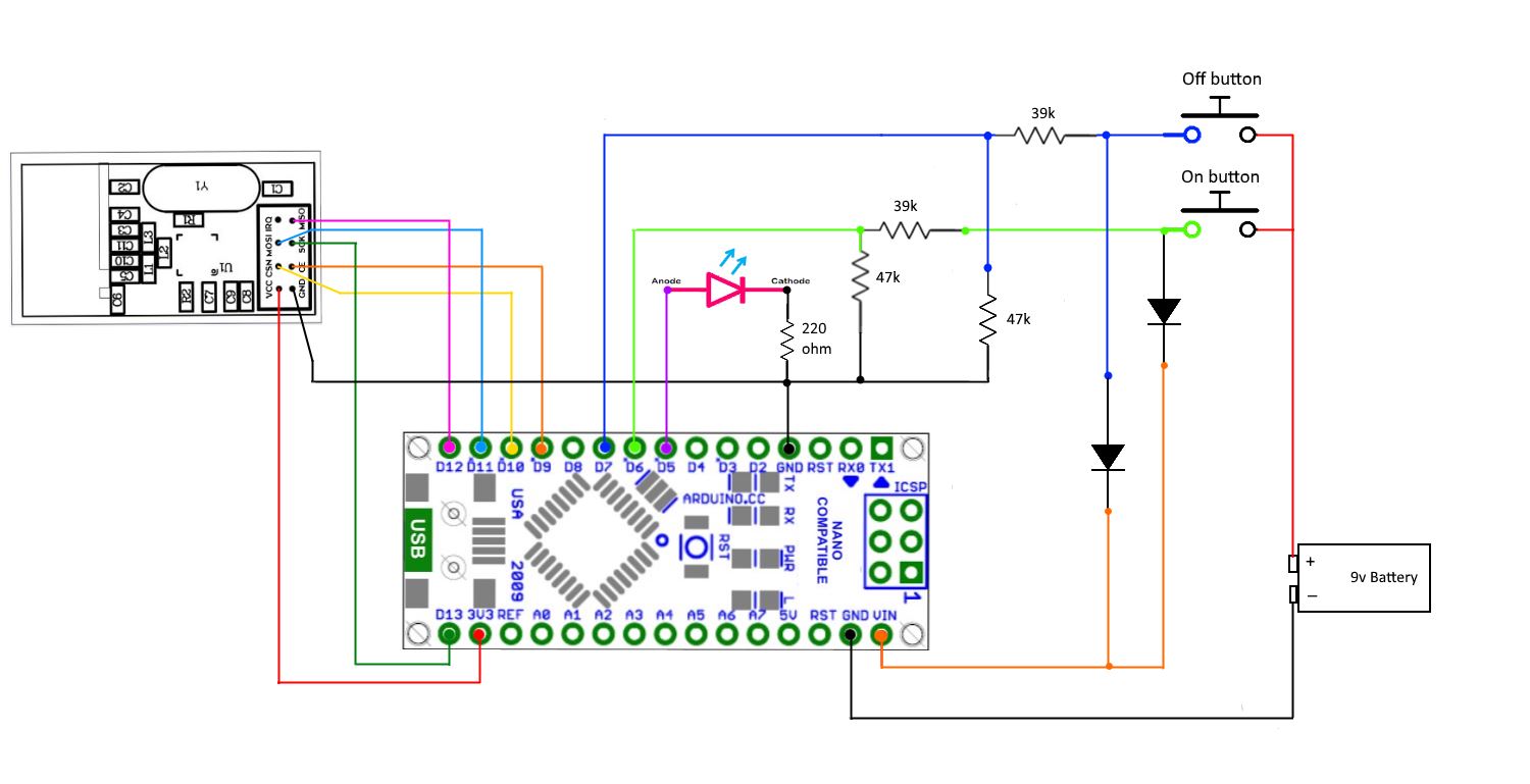
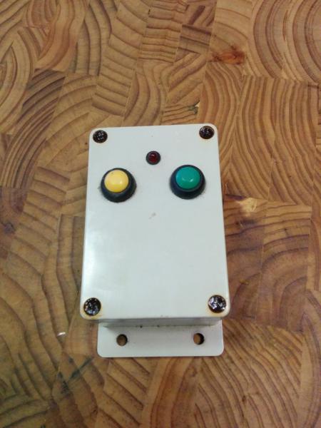
Progressed a bit further this weekend. have changed the remote a little and now only have two buttons and one led. The revised sketch is now shown above. The new circuit uses a 9v battery (because i have lots of these) and uses a voltage divider on inputs 6 and 7 to bring it down to around 5v
Circuit for the remote
-
I Have another update for this project.
***WARNING THIS PROJECT USES MAINS POWER AND SHOULD NOT BE ATTEMPTED BY ANYONE WHO IS NOT QUALIFIED TO DO SO.
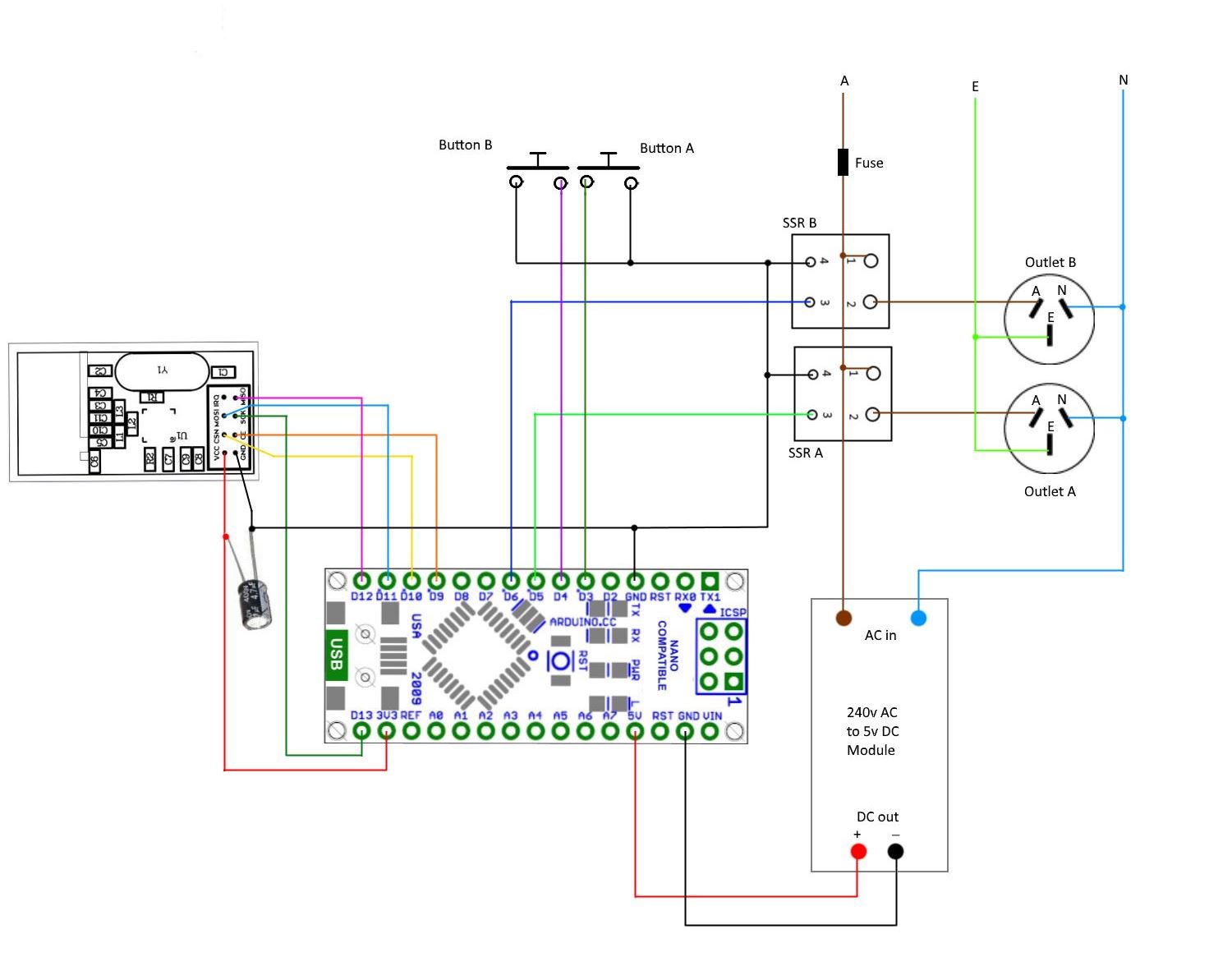
IT IS ILLEGAL IN MANY COUNTRIES FOR UN-QUALIFIED PERSONS TO WORK ON MAINS EQUIPMENT ****The power controller node is based on the MySensors relay with button actuator sketch. I am using solid state relays to control the AC mains, these should give good isolation via their optical isolators.
Two momentary push buttons are used to toggle the SSR’s locally. This can be handy if this node is the closest control point at the time. They are simply connected between GND and pins 3 and 4.
Both SSR’s can also be optionally set to turn off after a pre-set time has elapsed. The main use I have for this control is for a 240v pump attached to a water tank which is located away from the house. Sometimes in the past this pump has been left on accidentally and if the hose were to burst it would drain the tank before it was noticed.
At first I was simply going to use a LUA script in Domoticz to set a timer but if for some reason my server was to go down then the turn off may not be sent. So I decided to incorporate the timer into the node so that it will be a more reliable failsafe.
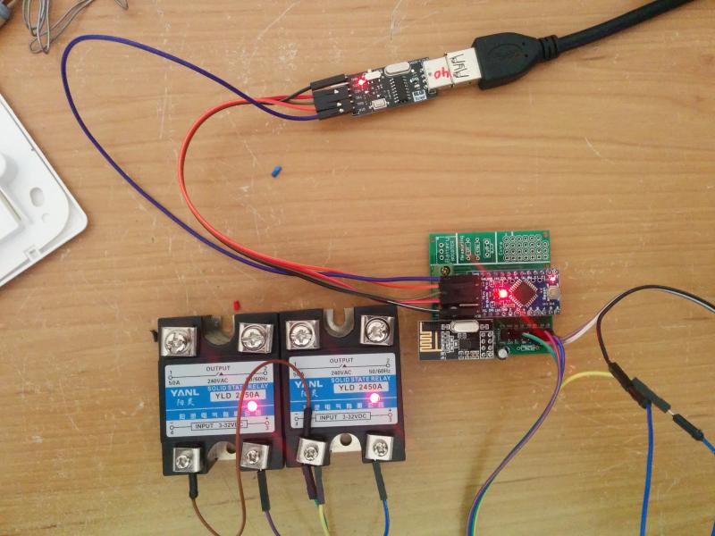
At this time I have not connected the SSR's to the mains (still waiting on the enclosure) but it all seems to be working ok
On the Bench
Current Sketch
/**

   DESCRIPTION

   This node will be used as a dual 240v ac socket controller
   The node will also respond to node to node messages from remote
   switching nodes

   It also has a built in timer for the Relays. This can be used to turn off
   the relay after a set time period. Set activeTimeA or activeTimeB to the number of
   minutes the relay is to stay on for. If no timer is desired then just set them to 0
*/

// Enable debug prints to serial monitor
#define MY_DEBUG

// Enable and select radio type attached
#define MY_RADIO_NRF24


// Enabled repeater feature for this node
//#define MY_REPEATER_FEATURE

#include <SPI.h>
#include <MySensors.h>
#include <Bounce2.h>

#define RELAY_ON 1
#define RELAY_OFF 0

#define SSR_A_ID 1   // Id of the sensor child
#define SSR_B_ID 2   // Id of the sensor child

const int buttonPinA = 3;
const int buttonPinB = 4;
const int relayPinA = 5;
const int relayPinB = 6;

int oldValueA = 0;
int oldValueB = 0;
int timerMarkerA = 0;
int timerMarkerB = 0;

bool stateA = false;
bool stateB = false;

unsigned long startMillisA = 0;            // holder for the time when relay first turns on
unsigned long startMillisB = 0;            // holder for the time when relay first turns on
unsigned long millisNow = 0;              // holder for the current time
unsigned long activeTimeA = 1;           // Time the realy will stay active in minutes. change this to suit your situation (use 0 to dissable timer)
unsigned long activeTimeB = 0;           // Time the realy will stay active in minutes. change this to suit your situation (use 0 to dissable timer)

Bounce debouncerA = Bounce();
Bounce debouncerB = Bounce();

MyMessage msgA(SSR_A_ID, V_STATUS);
MyMessage msgB(SSR_B_ID, V_STATUS);

void setup()
{

  pinMode(buttonPinA, INPUT_PULLUP); // Setup the button pin, Activate internal pull-up
  pinMode(buttonPinB, INPUT_PULLUP); // Setup the button pin, Activate internal pull-up
// Then set relay pins in output mode
  pinMode(relayPinA, OUTPUT);
  pinMode(relayPinB, OUTPUT);

  // After setting up the buttons, setup debouncer
  debouncerA.attach(buttonPinA);
  debouncerA.interval(5);
  debouncerB.attach(buttonPinB);
  debouncerB.interval(5);

  // Make sure relays are off when starting up
  digitalWrite(relayPinA, RELAY_OFF);
  digitalWrite(relayPinB, RELAY_OFF);


}

void presentation()  {
  // Send the sketch version information to the gateway and Controller
  sendSketchInfo("Mains Controller", "1.1");

  // Register all sensors to gw (they will be created as child devices)
  present(SSR_A_ID, S_LIGHT);
  present(SSR_B_ID, S_LIGHT);

}


void loop()
{

  debouncerA.update();
  int valueA = debouncerA.read();       // Get the update value
  if (valueA != oldValueA && valueA == 0) {
    send(msgA.set(stateA ? false : true), true); // Send new state and request ack back
  }
  oldValueA = valueA;

  debouncerB.update();
  int valueB = debouncerB.read();       // Get the update value
  if (valueB != oldValueB && valueB == 0) {
    send(msgB.set(stateB ? false : true), true); // Send new state and request ack back
  }
  oldValueB = valueB;

  if (activeTimeA != 0) {                //  Call timer function if needed
    relayTimerA();
  }

  if (activeTimeB != 0) {                //  Call timer function if needed
    relayTimerB();
  }


}


/*---------------Start of functions-----------------------*/


void relayTimerA() {

  millisNow = millis();           // get the current time
  /*
   -----------------------------
     Check relayPinA status and start timer event if relay is on.
          PORTD is used for digital pins 0 to 7
   ------------------------------
 */
  if ((bitRead(PORTD, relayPinA)) == RELAY_ON && timerMarkerA == 0 ) {
    timerMarkerA = 1;
    startMillisA = millisNow;
  }
  if (timerMarkerA == 1 && (millisNow - startMillisA) > (activeTimeA*60000)) {   // check to see if timeout has been reached
    digitalWrite(relayPinA, RELAY_OFF);                             // turn off relay A
    send(msgA.set(false));                                         // send message to controller so it knows the relay is now off
    timerMarkerA = 0;                                                 //reset marker
  }
  if ((bitRead(PORTD, relayPinA)) == RELAY_OFF && timerMarkerA == 1 ) {        //if  relay A has been turned off  cancell timer event
    timerMarkerA = 0;
  }

}


void relayTimerB() {

  millisNow = millis();           // get the current time
  /*
   -----------------------------
     Check relayPinB status and start timer event if relay is on.
          PORTD is used for digital pins 0 to 7
   ------------------------------
 */
  if ((bitRead(PORTD, relayPinB)) == RELAY_ON && timerMarkerB == 0 ) { //Check relayPinB status and start timer event if relay is on. (As this pin is set to output we can't use digitalRead to get status, so must read the port instead)
    timerMarkerB = 1;
    startMillisB = millisNow;
  }
  if (timerMarkerB == 1 && (millisNow - startMillisB) > (activeTimeB*60000)) {   // check to see if timeout has been reached
    digitalWrite(relayPinB, RELAY_OFF);                             // turn off relay B
    send(msgB.set(false));                                        // send message to controller so it knows the relay is now off
    timerMarkerB = 0;                                                 //reset marker
  }
  if ((bitRead(PORTD, relayPinB)) == RELAY_OFF && timerMarkerB == 1 ) {        //if  relay A has been turned off  cancell timer event
    timerMarkerB = 0;
  }

}


void receive(const MyMessage &message) {
  if (message.type == V_STATUS) {
   if (message.sender == 0) {       // this message is from gateway (node 0)
    switch (message.sensor) {
        case 1:
          stateA = message.getBool();
          digitalWrite(message.sensor + 4, stateA ? RELAY_ON : RELAY_OFF);
          break;
        case 2:
          stateB = message.getBool();
          digitalWrite(message.sensor + 4, stateB ? RELAY_ON : RELAY_OFF);
          break;

      }
    }
  else  {                                // message is not from gateway so must be from a remote
    switch (message.sensor) {
        case 1:
          stateA = message.getBool();
          digitalWrite(message.sensor + 4, stateA ? RELAY_ON : RELAY_OFF);
          send(msgA.set(stateA ? true : false));                // echo the message to the gateway so controller will be aware of the change
          break;
        case 2:
          stateB = message.getBool();
          digitalWrite(message.sensor + 4, stateB ? RELAY_ON : RELAY_OFF);
          send(msgB.set(stateB ? true : false));               // echo the message to the gateway so controller will be aware of the change
          break;

      }
    }

    // Write some debug info
    #ifdef MY_DEBUG
    Serial.print("Incoming change for sensor:");
    Serial.println(message.sensor);
    Serial.print("from node:");
    Serial.println(message.sender);
    Serial.print(", New status: ");
    Serial.println(message.getBool());
    #endif
  }
}
Wiring diagram
-
Got a working device under test now, will see how it goes switching lights and give it a try on the pump when I get time. I still have some changes i want to make on the sketch but it is working as expected at this time.
I had trouble finding a suitable case at a reasonable price for this project. The SSR's are around 80mm high once they are mounted on their heat sinks so I needed a fairly deep box. In the end I just used an old PC power supply case which has worked out ok. Although the node will be outside it will be located in the pump shed so will not be directly affected by the weather. I may need to add flyscreen to prevent insects from getting in.
The completed power control node
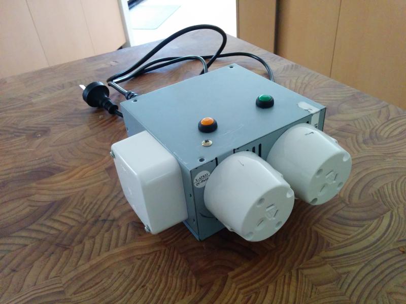
The inner workings. you can see the two buttons used to toggle the relays on and off. Channel 1 is switched by the orange button and channel 2 by the green.
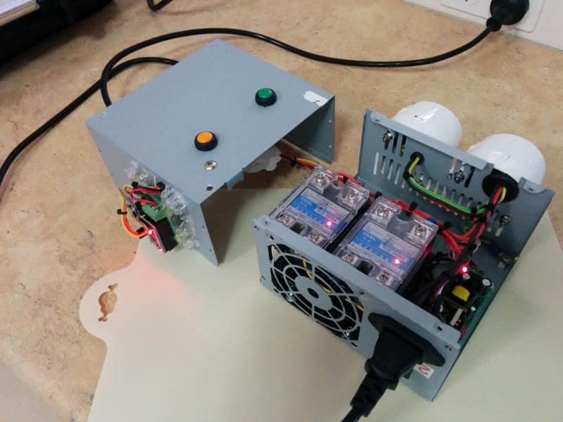
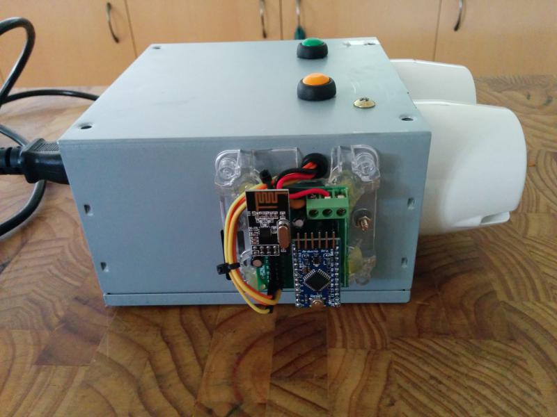
Even though there was room inside the box for the arduino I decided to mount it on the outside. This has several advantages, this being a metal case it would of had a drastic affect on the range if mounted inside. It will hopefully be less affected by the noise form the AC mains and it will mean I can upload sketch updates without being exposed to the mains voltages inside.
I have used the easy pcb from @sundberg84 I just had to cut off the aux part to get it to fit. I used hot glue to hold the board in place.
I will be testing with lights for a start to make sure it is reliable, then on to other things. The SSR's I have used are zero switching and from what I have read random switching would be a better choice for inductive loads. I already had these so will see how they go, if they prove problematic I will get some random switching and try them.
I have also completed the first remote node. The design is working well and with the infrequent use these remotes get I will be expecting to get close to the shelf life of the battery between battery changes. Well worth the minor inconvenience of a few seconds wait for it to boot and send the message.
-
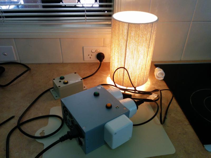
I now have this device connected to the water pump and it is working ok. The pump has turned on and off without fault while in use. The SSR's are running nice and cool as well so all seems to be correct. I did notice while testing that cfl bulbs would not turn completely off due to a small power bleed across the triac.
From what I have read this would seem to be normal and can be overcome by additional circuitry but they are working for the intended use. If you were to use this sketch/circuit for cfl's or very low powered items it may be best to just use standard relay modules instead.The final sketch is shown bellow , The only change has been to the timing part of the sketch. I have now included the ability to turn the timers on and off from Domoticz or whatever controller you are using. The state of the timer switches is now also stored in eeprom so it is reloaded if the node is power cycled.
The remote sketch remains as the one shown in the first post, it also is functioning as intended.
/** DESCRIPTION This node will be used as a dual 240v ac socket controller The node will also respond to node to node messages from remote switching nodes It also has a built in timer for the Relays. This can be used to turn off the relay after a set time period. Set activeTimeA or activeTimeB to the number of minutes the relay is to stay on for. If no timer is desired then just set them to 0 Timers can also be enabled/disabled by switches in your home automation controller. */ // Enable debug prints to serial monitor //#define MY_DEBUG // Enable and select radio type attached #define MY_RADIO_NRF24 // Enabled repeater feature for this node #define MY_REPEATER_FEATURE #include <SPI.h> #include <MySensors.h> #include <Bounce2.h> #define RELAY_ON 1 #define RELAY_OFF 0 #define SSR_A_ID 1 // Id of relay A #define SSR_B_ID 2 // Id of relay B #define TIMER_A_ID 3 // Id of timers switch A #define TIMER_B_ID 4 // Id of timers switch B const int buttonPinA = 3; //on/off button for relay A const int buttonPinB = 4; //on/off button for relay B const int relayPinA = 5; // SSR_A connected here const int relayPinB = 6; // SSR_B connected here int oldValueA = 0; int oldValueB = 0; int timerMarkerA = 0; // Used to tell if timer A is active int timerMarkerB = 0; // Used to tell if timer B is active bool stateA = false; bool stateB = false; bool timerStateA = false; bool timerStateB = false; unsigned long startMillisA = 0; // holder for the time when relay first turns on unsigned long startMillisB = 0; // holder for the time when relay first turns on unsigned long millisNow = 0; // holder for the current time unsigned long activeTimeA = 60; // Time the relay will stay active in minutes. change this to suit your situation (use 0 to dissable timer) unsigned long activeTimeB = 60; // Time the relay will stay active in minutes. change this to suit your situation (use 0 to dissable timer) Bounce debouncerA = Bounce(); Bounce debouncerB = Bounce(); MyMessage msgA(SSR_A_ID, V_STATUS); MyMessage msgB(SSR_B_ID, V_STATUS); void setup() { pinMode(buttonPinA, INPUT_PULLUP); // Setup the button pin, Activate internal pull-up pinMode(buttonPinB, INPUT_PULLUP); // Setup the button pin, Activate internal pull-up // Then set relay pins in output mode pinMode(relayPinA, OUTPUT); pinMode(relayPinB, OUTPUT); // After setting up the buttons, setup debouncer debouncerA.attach(buttonPinA); debouncerA.interval(5); debouncerB.attach(buttonPinB); debouncerB.interval(5); // Make sure relays are off when starting up digitalWrite(relayPinA, RELAY_OFF); digitalWrite(relayPinB, RELAY_OFF); // Set timers to last known state (using eeprom storage) timerStateA = loadState(TIMER_A_ID); timerStateB = loadState(TIMER_B_ID); } void presentation() { // Send the sketch version information to the gateway and Controller sendSketchInfo("Mains Controller", "1.2"); // Register all sensors to gw (they will be created as child devices) present(SSR_A_ID, S_LIGHT,"Relay A"); present(SSR_B_ID, S_LIGHT,"Relay B"); present(TIMER_A_ID, S_BINARY,"Timer Switch A"); present(TIMER_B_ID, S_BINARY,"Timer Switch B"); } void loop() { debouncerA.update(); int valueA = debouncerA.read(); // Get the update value if (valueA != oldValueA && valueA == 0) { send(msgA.set(stateA ? false : true), true); // Send new state and request ack back } oldValueA = valueA; debouncerB.update(); int valueB = debouncerB.read(); // Get the update value if (valueB != oldValueB && valueB == 0) { send(msgB.set(stateB ? false : true), true); // Send new state and request ack back } oldValueB = valueB; if (timerStateA == true and activeTimeA != 0){ //check if timer A is enabled relayTimerA(); // call timer A function } if (timerStateB == true and activeTimeB != 0){ //check if timer B is enabled relayTimerB(); // call timer B function } } /*---------------Start of functions-----------------------*/ void relayTimerA() { millisNow = millis(); // get the current time /* ----------------------------- Check relayPinA status and start timer event if relay is on. PORTD is used for digital pins 0 to 7 ------------------------------ */ if ((bitRead(PORTD, relayPinA)) == RELAY_ON && timerMarkerA == 0 ) { timerMarkerA = 1; startMillisA = millisNow; } if (timerMarkerA == 1 && (millisNow - startMillisA) > (activeTimeA*60000)) { // check to see if timeout has been reached digitalWrite(relayPinA, RELAY_OFF); // turn off relay A send(msgA.set(false)); // send message to controller so it knows the relay is now off timerMarkerA = 0; //reset marker } if ((bitRead(PORTD, relayPinA)) == RELAY_OFF && timerMarkerA == 1 ) { //if relay A has been turned off cancell timer event timerMarkerA = 0; } } void relayTimerB() { millisNow = millis(); // get the current time /* ----------------------------- Check relayPinB status and start timer event if relay is on. PORTD is used for digital pins 0 to 7 ------------------------------ */ if ((bitRead(PORTD, relayPinB)) == RELAY_ON && timerMarkerB == 0 ) { timerMarkerB = 1; startMillisB = millisNow; } if (timerMarkerB == 1 && (millisNow - startMillisB) > (activeTimeB*60000)) { // check to see if timeout has been reached digitalWrite(relayPinB, RELAY_OFF); // turn off relay B send(msgB.set(false)); // send message to controller so it knows the relay is now off timerMarkerB = 0; //reset marker } if ((bitRead(PORTD, relayPinB)) == RELAY_OFF && timerMarkerB == 1 ) { //if relay A has been turned off cancell timer event timerMarkerB = 0; } } void receive(const MyMessage &message) { if (message.type == V_STATUS) { if (message.sender == 0) { // check if message is from gateway (node 0) switch (message.sensor) { case 1: //incoming message is for relay A stateA = message.getBool(); digitalWrite(message.sensor + 4, stateA ? RELAY_ON : RELAY_OFF); break; case 2: //incoming message is for relay B stateB = message.getBool(); digitalWrite(message.sensor + 4, stateB ? RELAY_ON : RELAY_OFF); break; case 3: //incoming message is from relay A timer switch timerStateA = message.getBool(); if (timerStateA == false){ timerMarkerA = 0; } saveState(TIMER_A_ID, timerStateA); // Store timer state in eeprom break; case 4: //incoming message is from relay B timer switch timerStateB = message.getBool(); if (timerStateB == false){ timerMarkerB = 0; } saveState(TIMER_B_ID, timerStateB); // Store timer state in eeprom break; } } else { // message is not from gateway so must be from a remote switch (message.sensor) { case 1: //incoming message is for relay A stateA = message.getBool(); digitalWrite(message.sensor + 4, stateA ? RELAY_ON : RELAY_OFF); send(msgA.set(stateA ? true : false)); // echo the message to the gateway so controller will be aware of the change break; case 2: //incoming message is for relay B stateB = message.getBool(); digitalWrite(message.sensor + 4, stateB ? RELAY_ON : RELAY_OFF); send(msgB.set(stateB ? true : false)); // echo the message to the gateway so controller will be aware of the change break; } } // Write some debug info #ifdef MY_DEBUG Serial.print("Incoming change for sensor:"); Serial.println(message.sensor); Serial.print("from node:"); Serial.println(message.sender); Serial.print(" New status: "); Serial.println(message.getBool()); #endif } } -
I have a project in mind that I think is similar to yours. Essentially I would have one main unit that issues commands to numerous slaves. Your code is a bit confusing to me. I'm just wanting to make sure I am understanding it correctly. You basically have two pieces to this right? A remote control and then the pumps receiver right? So for all intensive purposes your controller is also your gateway. Are you able to communicate to say 20 other pumps using this same controller?
-
I have a project in mind that I think is similar to yours. Essentially I would have one main unit that issues commands to numerous slaves. Your code is a bit confusing to me. I'm just wanting to make sure I am understanding it correctly. You basically have two pieces to this right? A remote control and then the pumps receiver right? So for all intensive purposes your controller is also your gateway. Are you able to communicate to say 20 other pumps using this same controller?
@Danton-Barnes said:
You basically have two pieces to this right? A remote control and then the pumps receiver right?
Essentially yes the two nodes in this project are the remote and the pump control. Of course I still also have a MySensors gateway that is connected to my controller which is Domiticz .
So for all intensive purposes your controller is also your gateway.
Just to clear up the terminology, in MySensors
Controller is used to describe the (Home Automation) software that you can use to interact with your nodes.
Gateway is the device you build which is the bridge between your controller and your nodes. A gateway can also contain sensors
Nodes are the modules you build that contain the sensors/Actuators
Are you able to communicate to say 20 other pumps using this same controller?
Yes that would certainly be possible. You could do that in a number of ways depending on where the "pumps" were located.
If all the pumps were in the same spot you would just need to construct one Node and it could contain the 20 actuators used to control the pumps.
If the pumps are widely dispersed then you may need to build a node for each pump, you could still combine some on the same node if they were close together and able to be linked by wire.Each Node has its own address on the network and every sensor/actuator on that node has its own identifier as well. It is that information we can use to interact and control.
For example in this project my pump control node has two actuators that I have assigned the Id's of 1 and 2. This node has an address of 7 on the network, this address was assigned by the controller (Domoticz) but you can also assign the id manually in code if you like.
So my remote node uses this information to control the actuators on the pump control node. The code that does this is shown in the line below. The variable nodeId holds the address of the destination node and the variable sensorId holds the ID of the actuator on that node to be changed.
You would just need to use the addresses of your nodes and actuators
send(MyMessage(1, V_STATUS).setSensor(sensorId).setDestination(nodeId).set(false)); // send message to relay node to turn offIf you are going to use the MySensors network for you project you may still need to have a gateway and controller.
Having a controller could open up other possible methods you could use to control the "pumps" such as timed events or control via the internet. Many controllers also have apps for phones etc. that will allow your phone or tablet to switch the "pumps" -
I have updated the controller so it will boot up and can be locally switched even if no gateway is found. I have cleaned up the code a little bit as well. Now running on V2.1.1
/** DESCRIPTION This node will be used as a dual 240v ac socket controller The node will also respond to node to node messages from remote switching nodes It also has a built in timer for the Relays. This can be used to turn off the relay after a set time period. Set activeTimeA or activeTimeB to the number of minutes the relay is to stay on for. If no timer is desired then just set them to 0 Timers can also be enabled/disabled by switches in your home automation controller. */ // Enable debug prints to serial monitor #define MY_DEBUG // Enable and select radio type attached #define MY_RADIO_NRF24 #define MY_TRANSPORT_WAIT_READY_MS 3000 //set how long to wait for transport ready. #define MY_RF24_CHANNEL 84 // Enabled repeater feature for this node //#define MY_REPEATER_FEATURE #include <SPI.h> #include <MySensors.h> #include <Bounce2.h> #define RELAY_ON 1 #define RELAY_OFF 0 #define SSR_A_ID 1 // Id of relay A #define SSR_B_ID 2 // Id of relay B #define TIMER_A_ID 3 // Id of timers switch A #define TIMER_B_ID 4 // Id of timers switch B const int buttonPinA = 3; //on/off button for relay A const int buttonPinB = 4; //on/off button for relay B const int relayPinA = 5; // SSR_A connected here const int relayPinB = 6; // SSR_B connected here int oldValueA = 0; int oldValueB = 0; int timerMarkerA = 0; // Used to tell if timer A is active int timerMarkerB = 0; // Used to tell if timer B is active bool stateA = false; bool stateB = false; bool timerStateA = false; bool timerStateB = false; unsigned long startMillisA = 0; // holder for the time when relay first turns on unsigned long startMillisB = 0; // holder for the time when relay first turns on unsigned long millisNow = 0; // holder for the current time unsigned long activeTimeA = 60; // Time the relay will stay active in minutes. change this to suit your situation (use 0 to dissable timer) unsigned long activeTimeB = 60; // Time the relay will stay active in minutes. change this to suit your situation (use 0 to dissable timer) unsigned long heartbeatDelay = 120; // how often the heartbeat will be sent, in minutes unsigned long lastHeartbeat = millis(); // holder for last time heartbeat was sent Bounce debouncerA = Bounce(); Bounce debouncerB = Bounce(); MyMessage msgA(SSR_A_ID, V_STATUS); MyMessage msgB(SSR_B_ID, V_STATUS); void setup() { pinMode(buttonPinA, INPUT_PULLUP); // Setup the button pin, Activate internal pull-up pinMode(buttonPinB, INPUT_PULLUP); // Setup the button pin, Activate internal pull-up // After setting up the buttons, setup debouncer debouncerA.attach(buttonPinA); debouncerA.interval(5); debouncerB.attach(buttonPinB); debouncerB.interval(5); // set relay pins in output mode pinMode(relayPinA, OUTPUT); pinMode(relayPinB, OUTPUT); // Make sure relays are off when starting up digitalWrite(relayPinA, RELAY_OFF); digitalWrite(relayPinB, RELAY_OFF); // Set timers to last known state (using eeprom storage) timerStateA = loadState(TIMER_A_ID); timerStateB = loadState(TIMER_B_ID); } void presentation() { // Send the sketch version information to the gateway and Controller sendSketchInfo("Mains Controller", "1.4"); // Register all sensors to gw (they will be created as child devices) present(SSR_A_ID, S_BINARY,"Relay A"); present(SSR_B_ID, S_BINARY,"Relay B"); present(TIMER_A_ID, S_BINARY,"Timer Switch A"); present(TIMER_B_ID, S_BINARY,"Timer Switch B"); } void loop() { debouncerA.update(); int valueA = debouncerA.read(); // Get the update value if (valueA != oldValueA && valueA == 0) { stateA = !stateA; // Toggle the state send(msgA.set(stateA), false); // send new state to controller, no ack requested digitalWrite(relayPinA, stateA ? RELAY_ON : RELAY_OFF); // switch the relay to the new state } oldValueA = valueA; debouncerB.update(); int valueB = debouncerB.read(); // Get the update value if (valueB != oldValueB && valueB == 0) { stateB = !stateB; // Toggle the state send(msgB.set(stateB), false); // send new state to controller, no ack requested digitalWrite(relayPinB, stateA ? RELAY_ON : RELAY_OFF); // switch the relay to the new state } oldValueB = valueB; if (timerStateA == true and activeTimeA != 0){ //check if timer A is enabled relayTimerA(); // call timer A function } if (timerStateB == true and activeTimeB != 0){ //check if timer B is enabled relayTimerB(); // call timer B function } heartbeatCheck(); // call heartbeat function } /*---------------Start of functions-----------------------*/ void heartbeatCheck(){ millisNow = millis(); // get the current time if ((millisNow - lastHeartbeat) > (heartbeatDelay*60000)) { sendHeartbeat(); lastHeartbeat = millis(); #ifdef MY_DEBUG Serial.println("Heartbeat Sent" ); #endif } } void relayTimerA() { millisNow = millis(); // get the current time if (digitalRead(relayPinA) == RELAY_ON && timerMarkerA == 0 ) { //Check relayPinA status and start timer event if relay is on. timerMarkerA = 1; startMillisA = millisNow; } if (timerMarkerA == 1 && (millisNow - startMillisA) > (activeTimeA*60000)) { // check to see if timeout has been reached digitalWrite(relayPinA, RELAY_OFF); // turn off relay A send(msgA.set(false)); // send message to controller so it knows the relay is now off timerMarkerA = 0; //reset marker } if (digitalRead(relayPinA) == RELAY_OFF && timerMarkerA == 1 ) { //if relay A has been turned off cancel timer event timerMarkerA = 0; } } void relayTimerB() { millisNow = millis(); // get the current time if (digitalRead(relayPinB) == RELAY_ON && timerMarkerB == 0 ) { // Check relayPinB status and start timer event if relay is on. timerMarkerB = 1; startMillisB = millisNow; } if (timerMarkerB == 1 && (millisNow - startMillisB) > (activeTimeB*60000)) { // check to see if timeout has been reached digitalWrite(relayPinB, RELAY_OFF); // turn off relay B send(msgB.set(false)); // send message to controller so it knows the relay is now off timerMarkerB = 0; //reset marker } if (digitalRead(relayPinB) == RELAY_OFF && timerMarkerB == 1 ) { //if relay B has been turned off cancel timer event timerMarkerB = 0; Serial.println("timer B cancelled" ); } } void receive(const MyMessage &message) { if (message.type == V_STATUS) { if (message.sender == 0) { // check if message is from gateway (node 0) switch (message.sensor) { case 1: //incoming message is for relay A stateA = message.getBool(); digitalWrite(relayPinA, stateA ? RELAY_ON : RELAY_OFF); break; case 2: //incoming message is for relay B stateB = message.getBool(); digitalWrite(relayPinB, stateB ? RELAY_ON : RELAY_OFF); break; case 3: //incoming message is from relay A timer switch timerStateA = message.getBool(); if (timerStateA == false){ timerMarkerA = 0; } saveState(TIMER_A_ID, timerStateA); // Store timer state in eeprom break; case 4: //incoming message is from relay B timer switch timerStateB = message.getBool(); if (timerStateB == false){ timerMarkerB = 0; } saveState(TIMER_B_ID, timerStateB); // Store timer state in eeprom break; } } else { // message is not from gateway so must be from a remote switch (message.sensor) { case 1: //incoming message is for relay A stateA = message.getBool(); digitalWrite(relayPinA, stateA ? RELAY_ON : RELAY_OFF); send(msgA.set(stateA ? true : false)); // echo the message to the gateway so controller will be aware of the change break; case 2: //incoming message is for relay B stateB = message.getBool(); digitalWrite(relayPinB, stateB ? RELAY_ON : RELAY_OFF); send(msgB.set(stateB ? true : false)); // echo the message to the gateway so controller will be aware of the change break; } } // Write some debug info #ifdef MY_DEBUG Serial.print("Incoming change for sensor:"); Serial.println(message.sensor); Serial.print("from node:"); Serial.println(message.sender); Serial.print(" New status: "); Serial.println(message.getBool()); #endif } } -
I use a similar design for a wireless door bell. To not be forced to push the button while the node is booting, I charge a large capacitor when a button is pressed.
Hello! It looks like you're interested in this conversation, but you don't have an account yet.
Getting fed up of having to scroll through the same posts each visit? When you register for an account, you'll always come back to exactly where you were before, and choose to be notified of new replies (either via email, or push notification). You'll also be able to save bookmarks and upvote posts to show your appreciation to other community members.
With your input, this post could be even better 💗
Register Login