My 2AA battery sensor


  • Hardware Contributor

    Don't know if it's too obviuos but I haven't seen many basic designs so I thought I'd share mine. I have 10+ of these with runtime 6-8 months with very good results.

    Worth to note is that this "basic" design is based on a normal 3.3V 8MHz Arduino Pro Mini with just the voltage regulator and power led removed. The other common low-power tweak with new bootloader, decreased clock speed and disabled brown out voltage detection is very nice but not a part of this design because I think it is one step beyond "basic". So keep it simple for now... (Or look here.)

    It's a normal battery powered slim one piece unit with battery monitoring and room for small sensors inside. In the picture a DHT22 has been squeezed but with better preparations there'll be more useable space.
    Some benefits I noticed with this design is:

    • Easy access to the pro mini serial pins, the reset button and to view the pin 13 led.
    • Easy remove/replace batteries.
    • Easy in/out of components since the just attached in place with their firm-flexible wires.
    • The "keyhole" in the cap is still available so the unit easily can hang on the wall.
    • The radio is located far from the wall-side and with reasonable small risk of getting in the shadow behind the batteries.
    • Small but still good battery life using (the most?) common standard batteries.
    • (I'd thought I'd put good waf here but she said the box color was "too gray" )

    The cost with building this sensor is that it requires some soldering and small/short wires work. (I prefer small/medium size "bread board type" wires to this.). I unsoldered the radio module pin headers and trimmed the ones on the step-up. After building 10 of these in 3 batches I've focused on productivity and less on the product. So I'm aware of improvements and maybe I'll introduce some in my next ongoing batch of 10.
    The 3.3V stepup-supply feeds the arduino and sensors that requires 3.3V to work. The radio is powered straight from the batteries because it's high qauality demand on its supply and that it's good with a voltage all the way down to 1.9V. I still use the 4,7uF capacitor on radio as precaution.
    Since its battery and low power is wanted, I always remove the voltage regulator and power led from the Arduino pro mini and the power led from the step-up regulator (or the series resistor).
    I set my power monitoring to report linear with 1.9V as 0% (Vmin_radio) and 3.3V as 100% (instead of 3.44 just to increase resolution). Power consumption looks very good. I usually use normal or high frequency update in my nodes (30s - 3min) and I've tried with really poor used batteries but all my batterylevels in datamine (Vera-plugin) are looking good. I've measured ~1mAac/0.1mAdc current draw in sleep mode. Considering the results from reality with my nodes with longer sleep durations, the mAdc value is closest to the truth.
    m26872-bas-sensor-prototyp-1.jpg

    More photos of a complete node to be found here below.

    Main material (note that some links are for >1pcs). All except battery holder are from MySensors store.

    Edit:
    I forgot to list the 2 resistors and 1 capacitor for battery monitoring as well as the sensor dependent 4k7 pullup resistor (if used). The battery monitoring circuit is under the 2-row proto-pcb and the pullup under the arduino. See the build site and store for more info. With a 3-row proto-pcb I'd place the pullup here as well.
    The 4.7uF cap for radio is of course straight on top between vcc and gnd, but a little above so wires can be soldered here too.
    I can also mention that I find a good order for making these are:

    1. Glue the battery holder to the case "bottom".
    2. a. Pre-assemble arduino with radio soldering as short wires as possible. And attach all (~30mm) wires leaving these two.
      b. Pre-a. the proto-pcb with all its components and with the step-up regulator.
      c. Pre-a. sensor(s) that will be used.
    3. Connect all things made in the previous step.
    4. Connect battery when needed but don't put it all in to case until software has been loaded and first tests been done.

    As always; if unsure or in trouble; test individual parts before putting them together.

    Edit 2:
    Here's the layout with connections. Since the schematic is simple and covered elsewhere at the Build site I found it more informative to show the design as a layout with wiring.
    layout.PNG

    Edit 3:
    Some example sketches are found further below in this thread. E.g.
    http://forum.mysensors.org/topic/486/my-2aa-battery-sensor/37

    Then the usual ads linked from the Bom above:


  • @m26872 said:

    DO NOT FEED THE RADIO WITH THIS

    why?


  • Hardware Contributor

    @Tibus Tests and forum experience shows that the radio is too noise or ripple sensitive and will work with very poor performance. Relatively large low-ESR (expensive) capacitor can compensate for this, but I prefer to simply bypass the stepup to the radio. If you're not aware of this issue you'll look forward to a lot of frustration with your setup. Look here for some more info.


  • Hardware Contributor

    I updated the first post regarding sleep mode power consumption. Current draw <0.1mA was too optimistic. My Fluke 87 detected mostly AC current. Beginners mistake and really embarrassing. I excuse me with that I do this hobby between 1 an 2 am.

    Edit: This post should have been more elaborate. Please read further below for more info. To sum up - it's pretty good after all.


  • Hi @m26872

    The radio is powered straight from the batteries because it's high qauality demand on its supply and that it's good with a voltage all the way down to 1.9V. I still use the 4,7uF capacitor on radio as precaution.

    So straigh the setup look like this ? battery > stablize regulator > radio ?

    Since its battery and low power is wanted, I always remove the voltage regulator and power led from the Arduino pro mini and the power led from the step-up regulator (or the series resistor).

    Do you mind to share the how to?

    I set my power monitoring to report linear with 1.9V as 0% (Vmin_radio) and 3.3V as 100% (instead of 3.44 just to increase resolution). Power consumption looks good.

    Which method do you use? voltage divider or the using internal vRef ?

    Thanks


  • Hardware Contributor

    @funky81 said:

    Hi @m26872

    The radio is powered straight from the batteries because it's high qauality demand on its supply and that it's good with a voltage all the way down to 1.9V. I still use the 4,7uF capacitor on radio as precaution.

    So straigh the setup look like this ? battery > stablize regulator > radio ?

    No. There are two parallell supplies from the same battery. One is simple battery->radio and the other one battery->step-up-regulator->arduino (and sensors).

    Since its battery and low power is wanted, I always remove the voltage regulator and power led from the Arduino pro mini and the power led from the step-up regulator (or the series resistor).

    Do you mind to share the how to?

    There are descriptions on the build site. Instead of cutting the traces I just unsolder the regulator (the black piece with 5 legs) and the red power led (usually right next to it). If you're planning to reuse any, it's probably better to cut traces or unsolder series resistors. For the step-up in particular it's easy to see which resistor the led connects to.

    I set my power monitoring to report linear with 1.9V as 0% (Vmin_radio) and 3.3V as 100% (instead of 3.44 just to increase resolution). Power consumption looks good.

    Which method do you use? voltage divider or the using internal vRef ?

    Because of the step-up regulator the internal vRef-method isn't possible. I use voltage divider from build site and the code I posted earlier here. But for 2AAs use VMIN=1.9, VMAX= 3.3V and Volts-per-bit = 0.003363075; Vmin and Vmax you can adjust if you want.

    Thanks

    You're welcome.

    Edit: Logical level difference between radio and arduino is outside specification when radion operates at 1.9V and arduino at 3.3V, but from my own tests and experiemce 1.9 is working ok as a very low limit. A battery alarm should of course be set above 0% anyhow.


  • Hardware Contributor

    As a general comment I'd like to complete the cross reference to this thread. It says why you should avoid the china step-up converter due to its high quiescent power draw (~ 1mA). If space is available e.g. a 4AA-supply via APM inbuilt regulator can give <25% sleep mode power consumption.

    Edit: After a few months testing, I'm reassessing the efficiency of the China step-up. See below in this thread.


  • @m26872 said:

    runtime 1-4 weeks

    So this gives a runtime of 1-4 weeks? I am just starting out and wanted to confirm this. There are other posts claiming 6 months but I suspect that is in theory and the reality is 1-4 as you have experienced. Also, are any of your sensors interrupt driven that only wake up on outside feedback such as door switch? - I wonder if that will have more battery life.


  • Hardware Contributor

    @MatrixIII No no, that was for how long I have had my system running when I wrote the first post in this thread. The battery time in practice highly depends on how much the node sleeps. Always on and always asleep will give you the extreme. I'd say 6 months is very reasonable. I'll see if I can show some examples....


  • Hardware Contributor

    Ok here are some of my logged battery levels. Note that some nodes had been running before logging was turned on and that I also like to drain already used batteries. I'll leave to the reader to extrapolate the trends and estimate life time, but I suspect that the last 20% shouldn't be taken into account. First exampel shows briefly why;

    First one odd but illustrating example where I used two rechargeable 700mAh AAAs with one DS18B20, varying (very) temp and only 30s sleep. Any nodes transmission activity will temporary produce a lower voltage reading and make the curve look noisy. This band grows thick near the end of life and these low spikes are the ones to keep an eye on. Apart from that we see the typical "tilted S"-shaped battery discharge curve.
    Nod2.png


  • Hardware Contributor

    Next one is a rather nervous DHT22 with 30s sleep and supplied by two (initially fresh) normal alkaline AAs.
    Nod16.png


  • Hardware Contributor

    This one has two DS18B20s, 30s sleep. The sensors are attached to a central heating pipe. The heating system was turned on 1 Nov which is visible as new more battery consuming trend.
    Nod101.png


  • Hardware Contributor

    Here is the interrupt-driven (front) door switch sensor as requested. Unfortunately not with fresh AAs. Since it's almost always sleeping I think the power draw is surprisingly high. Explanation is of course the 1mA to the china step-up.
    Node110.png


  • Hardware Contributor

    Finally are there two nodes started up at the same time, equally equipped with one BMP180 and one DHT22 each. Sleep time are more normal 15+5min. (15+5 because I now have learned to filter the DHT-readings and I do this here by measure a value 5 min before the real processing for avaraging purpose and to reduce risk of invalid readings.)
    I'm confident this will survive 6 months since the decrease rate is 5% per month and it's still in the beginning of the "tilted S". The upper curve is with fresh batteries, the lower with used.
    Nod105106.png


  • Admin

    Great job with the graphs! Really interesting.


  • Contest Winner

    Very good analysis. I have just bought two lipo cells and a charger and a bunch of 9V battery cables. Sometime next year I hope to get the time to evaluate their use for power source to the sensors. Then I will also test my slightly more conservative battery level circuit described here.


  • Hardware Contributor

    Thanks.

    I thought someone would ask why I expect a 3000mAh battery to supply 1mA for 6 months ?


  • Hero Member

    @m26872 said:

    Thanks.

    I thought someone would ask why I expect a 3000mAh battery to supply 1mA for 6 months ?

    Nice Work!! Oh and with the mods you have in place, I don't think you should have much problem getting to 6 months.. 🙂


  • Hero Member

    @m26872 said:

    I thought someone would ask why I expect a 3000mAh battery to supply 1mA for 6 months ?

    Ok, I'll be the straight man here: why do you expect a 3000mAh battery to supply 1mA for around 4400 hours?


  • Hardware Contributor

    @Zeph Thank you.
    Because it's 90% mAac (from dc source) and I think the china step-up isn't really that crappy after all. Energizing-deenergizing a a coil with no load will look like this without any real power produced. Of course there are loss power and wear on battery etc, but not compareable to 1mAdc. Deeper investigation to this should be the subject of a new thread.


  • Hero Member

    I'm getting about 3-4 months from my less active sensors, and the only hardware mod I'm using is the Arduino LED removal. So I can image removing the regulator and step LED would save a fair amount of energy.

    I really need to get around to removing those....


  • This are my results, with low power arduino powerd on 2 AA alkaline batteries.

    Door/window sensor (front door - opens frequently). On ocrober 4 battery status 64%, december 18 62% (still at 62%). 100% spike is when I reprogram my sensor. In 75 days battery drops for 2 % -> 100% in more than 10 years.
    Code is available on GitHub.

    EasyIoT server battery status
    18-12-2014 22-14-47.png

    Temperature and humidity sensor with DHT22 and step up regulator. Arduino and NFR24L is powered directly on 2 AA batteries, DHT22 is powered on step up regulator but only when measure is taken. Battery drops for 14% in 75 days. Actually this design is not so good. I'm testing new design without step up regulator and better temperature/humidity sensor. 2AA alkaline batteries could last 10 years.
    18-12-2014 22-25-57.png

    This is my water leak sensor. I'm using 2 wasted AA batteries for testing, and voltage actually rise. Current consumption is about 6uA (self discharge is about 10 times bigger) practically all the time.
    upload-2b52408a-f0bd-43b0-a997-047e6dfa1995


  • Hardware Contributor

    @dopustko Looks nice. Can you please share a more detailed description of your hardware?
    Edit: I searched and saw that you're running at 1MHz and soon with HTU21T. Very elegant!


  • @m26872 here is my complete description for MySensors door/window sensor. For other sensors I will add descriptions in the future...


  • Hardware Contributor

    @dopustko Great! I love your low-power guide. Wow! That should be mandatory for all sensors that work below 3.3V like e.g. a door switch. And you're able to use the internal battery monitoring method and all.
    Also, when I looked at your diagram I realized that I probably did a mistake with my door switch connection to arduino and have a substantial current draw through the switch. If true it means that the step-up is innocent.


  • @m26872 In fact most of sensors can work on 2 AA batteries without step up regulator if sensor is selected carefully. That also minimize number of components and battery consumption.
    I'm using 1M pull up resistor instead of internal resistor (50-60K) - this lower power consumption. 1M is quite big but wires are short, so it's working ok.


  • Hi @dopustko , i've checked your cool website. can I ask few question regarding your setup?
    I saw this page, in order to get low power consumption, you did burn fuse and disable brown-out? Possible to use it without usbtinyisp?


  • @funky81 Thx. You can burn fuses with other Arduino - that's how I do it. Just google ArduinoISP.


  • Good info here. Thought comes to mind about using a small solar cell off a defectivet walkway light to add a little charge back in to the system, when there is any kind of light around.


  • Hardware Contributor

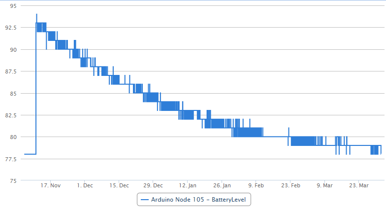
    Just an update on my battery levels. My VeraLite Datamine-plugin won't longer plot for me. I suspect I'm out of VeraLite memory to handle all the data. This is it. (Look above for last graphs.)
    Node 16: BatteryLevel 51
    Node 101: Dead 03 Feb
    Node 110; BatteryLevel 57
    Node 105: BatteryLevel 80
    Node 106: BatteryLevel 53
    As I hoped, the decrease rate for 105 and 106 is now less than 5% per month and 6-month target is already passed by half.
    The revenge of the Chinese step-up ?!


  • Hardware Contributor

    Someone else noticed that one of the two batteries drained by the step-up always has negative(!) charge? Due to the AC-load? Could it be possible to extend battery life by adding some kind of capacitor?


  • Hardware Contributor

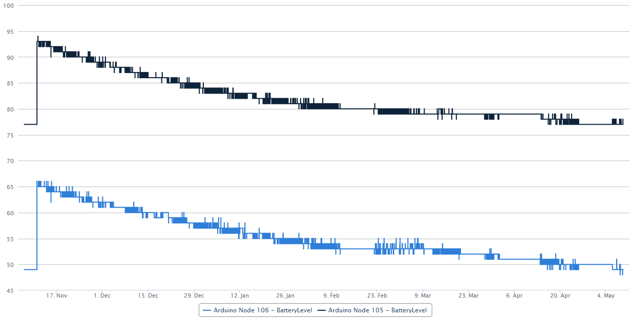
    Node 105 and 106 down just 1% since last post (22 days ago). Not bad. Relatively stable readings and low activity, but it doesn't matter since we're all expected the sleep mode consumption to be the worst.


  • @EasyIoT: Thank you for your nice descriptions of the low power sensors.
    I have some questions regarding the temperature sensor:
    Did you use a "Low power modified" Arduino for that as well?
    How are you able to power the sensor via the step-up only when needed? Do you power the step-up via an digital pin or something?

    @m26872: Also thanks for your design. I am thinking of building something similar. So you got now about 5% battery drop per month using the china stepup with desoldered LED?


  • Hardware Contributor

    @daenny said:

    So you got now about 5% battery drop per month using the china stepup with desoldered LED?

    Today I read Node 105: 78% and Node 106: 51%. That's only 2% in the last 38 days.

    nod105_20150331.PNG

    Edit: Perhaps using the "%" here is a little careless, but I think everyone knows that we're talking battery level.


  • @daenny yes, I'm using DO pin and MOSFET connected to step up regulator. But this is complicated solution. I'ts better to use different temperature sensor which can operate down to 1.8V. Right now I'm testing custom board with NRF24L and HTU21D (it's not cheap, but it can work down to 1,8V). Results are pretty good. Temperature and humidity sensor can operate more than 5 years on 2 AA batteries. For example door window sensor and water leak sensor can work more than 10 years on 2 AA batteries. It's seems that for those sensors AA batteries are overkill.


  • @m26872 I still dont get it. Why I cant get the same efficient power like you.
    I already follow all of your requirement in the first thread - difference only I use breadboard.
    The minimum consumption (sleep) that I've got still 2.4mA, compare to you, it still huge differences. I dont know what's wrong with my setup.

    My sketch wake up every 10s (consumption up to 3.5mA), while sleep the lowest is 2.4mA.

    #include <avr/sleep.h>    // Sleep Modes
    #include <MySensor.h>
    #include <SPI.h>
    
    MySensor gw;
    #define BATTERY_SENSE_PIN 
    #define SLEEP_IN_MS 86400000 // 1 day
    #define PROD false
    
    int oldBatLevel;
    
    void setup()
    {
      gw.begin(NULL,1);
      gw.sendSketchInfo("Basic-Sketch-MySensor", "1.0");
    
    
      pinMode(2,INPUT);
      digitalWrite (2, LOW);
    
      pinMode(3,INPUT);
      digitalWrite (3, LOW);
    
      pinMode(4,OUTPUT);
      digitalWrite (4, LOW);
    
      pinMode(5,INPUT);
      digitalWrite (5, LOW);
    
      pinMode(6,INPUT);
      digitalWrite (6, LOW);
    
      pinMode(7,INPUT);
      digitalWrite (7, LOW);
    
      pinMode(8,INPUT);
      digitalWrite (8, LOW);
      
      oldBatLevel = -1; 
    
      sendValue();
      Serial.println("Startup Finished");
      TurnOnLed();
    }
    
    void TurnOnLed(){
    
        digitalWrite(4,HIGH);
     gw.sleep(1000);
            digitalWrite(4,LOW);
      
      gw.sleep(100);
    }
    
    void loop ()
    {  
      sendValue();
      gw.sleep(1000*10);
    }  // end of loop
    
    void sendValue()
    {
      gw.powerUp(); 
    
      int batLevel = getBatteryLevel();
      if (!PROD){
        gw.sendBatteryLevel(batLevel);  
        TurnOnLed();
      }
      else{
        if (oldBatLevel != batLevel)
        {
          gw.sendBatteryLevel(batLevel);   
          oldBatLevel = batLevel;
          TurnOnLed();
        }
      }
    
      gw.powerDown(); 
    }
    
    // Battery measure
    int getBatteryLevel ()
    {
      int results = (readVcc() - 2000)  / 10;  
    
      if (results > 100)
        results = 100;
      if (results < 0)
        results = 0;
      return results;
    } // end of getBandgap
    
    // when ADC completed, take an interrupt
    EMPTY_INTERRUPT (ADC_vect);
    
    long readVcc() {
      long result;
      // Read 1.1V reference against AVcc
      ADMUX = _BV(REFS0) | _BV(MUX3) | _BV(MUX2) | _BV(MUX1);
      delay(2); // Wait for Vref to settle
      noInterrupts ();
      // start the conversion
      ADCSRA |= _BV (ADSC) | _BV (ADIE);
      set_sleep_mode (SLEEP_MODE_ADC);    // sleep during sample
      interrupts ();
      sleep_mode ();
      // reading should be done, but better make sure
      // maybe the timer interrupt fired
      while (bit_is_set(ADCSRA,ADSC));
      result = ADCL;
      result |= ADCH<<8;
      result = 1126400L / result; // Back-calculate AVcc in mV
    
      return result;
    }```

  • Hardware Contributor

    @funky81 said:

    @m26872 I still dont get it. Why I cant get the same efficient power like you....

    I see that your sketch uses the internal battery monitoring method. That isn't possible when using the design as in this threads subject, with a step-up regulator that makes Vbat different from Vcc. Are you sure you're not confusing my design with EaysIoTs ?

    Anyhow, I can't explain the sleep mode consumption, it seems like something isn't sleeping like it should.

    Here's my sketch for Node 105/106:

    // Egen kombo-nod för DHT22, BMP180 och batterimonitering.
    // 20141019
    // DHT-22 Working voltage: DC 3.3-5.5V (so connect after step-up regulator). http://www.adafruit.com/datasheets/Digital%20humidity%20and%20temperature%20sensor%20AM2302.pdf
    // BMP180 (compatible with BMP085) working voltage 1.8-3.6V. Different boards with different power and pullups. Datasheet for ic only: http://www.adafruit.com/datasheets/BST-BMP180-DS000-09.pdf 
    #include <SPI.h>
    #include <MySensor.h>  
    #include <DHT.h>
    #include <Wire.h>
    #include <Adafruit_BMP085.h> // N.b. The new library includes the function readSealevelPressure() 
    
    #define NODE_ID 106  // Manually asign Node Id  <<<<<<<<<<<<<<<<<<<  ENTER THIS !!!!
    #define ONE_WIRE_BUS 3 // Pin where dallase sensor bus is connected. <<<<<<<<<<<<<<<  DON'T FORGET 4k7 PULL-UP !!! >>>>>>>>>>>>>>>>
    #define VBAT_PER_BITS 0.003363075  // Calculated volts per bit from the used battery montoring voltage divider.   Internal_ref=1.1V, res=10bit=2^10-1=1023, Eg for 3V (2AA): Vin/Vb=R1/(R1+R2)=470e3/(1e6+470e3),  Vlim=Vb/Vin*1.1=3.44V, Volts per bit = Vlim/1023= 0.003363075
    #define VMIN 1.9  // Battery monitor lower level. Vmin_radio=1.9V
    #define VMAX 3.3  //  " " " high level. Vmin<Vmax<=3.44
    #define CHILD_ID_HUM 0
    #define CHILD_ID_TEMP 1
    #define BARO_CHILD 2
    //#define TEMP_CHILD 3  // Commented since don't need the Bmp tempsensor
    #define HUMIDITY_SENSOR_DIGITAL_PIN 3  // <<<<<<<<<<<<<<<<<<<<<<<<  Use 4k7 Pull-up. MySensors webpage doesn't use, datasheet does. Adafruit does https://learn.adafruit.com/dht/using-a-dhtxx-sensor
    
    unsigned long SLEEP_TIME = 15*60000; //  sleep time between reads (in milliseconds)
    unsigned long preSleepTime = 5*60000; //  sleep time for extra pre hum-reading for simple avaraging filter
    Adafruit_BMP085 bmp = Adafruit_BMP085();      // Digital Pressure Sensor 
    MySensor gw;
    DHT dht;
    float lastTemp;
    float lastHum;
    float lastPressure = -1;
    //float lastBmpTemp = -1; // Commented since don't need the Bmp tempsensor
    MyMessage msgHum(CHILD_ID_HUM, V_HUM);
    MyMessage msgTemp(CHILD_ID_TEMP, V_TEMP);
    //MyMessage tempMsg(TEMP_CHILD, V_TEMP); // Commented since don't need the Bmp tempsensor
    MyMessage pressureMsg(BARO_CHILD, V_PRESSURE);
    int BATTERY_SENSE_PIN = A0;  // select the input pin for the battery sense point
    int oldBatteryPcnt = 0;
    
    void setup()  
    { 
      analogReference(INTERNAL);    // use the 1.1 V internal reference for battery level measuring
      delay(500); // Allow time for radio if power used as reset <<<<<<<<<<<<<< Experimented with good result 
      gw.begin(NULL,NODE_ID); // Startup and initialize MySensors library. Set callback for incoming messages. 
      dht.setup(HUMIDITY_SENSOR_DIGITAL_PIN); 
    
      gw.sendSketchInfo("EgHumBarTemBatv2", "2.0 20141110");   // Send the Sketch Version Information to the Gateway
      
      if (!bmp.begin()) {
    	Serial.println("Could not find a valid BMP085 sensor, check wiring!");
    	while (1) {  }
      }
    
      gw.present(CHILD_ID_HUM, S_HUM);   // Register all sensors to gw (they will be created as child devices)
      gw.present(CHILD_ID_TEMP, S_TEMP);
      gw.present(BARO_CHILD, S_BARO);
    //  gw.present(TEMP_CHILD, S_TEMP); // Commented since don't need the Bmp tempsensor
      
    }
    
    void loop()      
    {  
      delay(dht.getMinimumSamplingPeriod());
      
      float humidity_1 = dht.getHumidity();
      if (isnan(humidity_1)) {
    	  Serial.println("Failed reading humidity_1 from DHT");
      } 
    //  else {
    //      Serial.print("Hum1: ");
    //      Serial.println(humidity_1);
    //  }  
      
      gw.sleep(preSleepTime); //sleep shortly until the "real" processing happens
      
      delay(dht.getMinimumSamplingPeriod());
    
      float humidity_2 = dht.getHumidity();
      if (isnan(humidity_2)) {
    	  Serial.println("Failed reading humidity_2 from DHT");
      } 
    //  else {
    //      Serial.print("Hum2: ");
    //      Serial.println(humidity_2);
    //  }
      if ( isnan(humidity_1) && isnan(humidity_2) ) {
    	Serial.println("Failed reading humidity_1 and humidity_2 from DHT");
      }
      else if ( isnan(humidity_2) && !isnan(humidity_1) ) { // && abs(humidity_1-lastHum)>2. ) {  // Ev hysteres
    	gw.send(msgHum.set(humidity_1, 1));
    	lastHum = humidity_1;
    //    Serial.println("Humidity_1 sent to gw.");
      } 
      else if ( isnan(humidity_1) && !isnan(humidity_2) ) { // && abs(humidity_2-lastHum)>2. ) {
    	gw.send(msgHum.set(humidity_2, 1));
    	lastHum = humidity_2;
    //    Serial.println("Humidity_2 sent to gw.");
      }  
      else {
    //    Serial.println("Else mean calc");
    	float humidity_m = (humidity_1+humidity_2)/2. ;  // Averageing the two.
    //    if ( abs(humidity_m-lastHum) > 2. ) {  
    	  gw.send(msgHum.set(humidity_m, 1));
    	  lastHum = humidity_m;
    //      Serial.println("The mean humidity_m sent to gw.");
    //    }
      }
    
      float temperature = dht.getTemperature();
      if (isnan(temperature)) {
    	  Serial.println("Failed reading temperature from DHT");
      } else if (temperature != lastTemp) {
    	lastTemp = temperature;
    	gw.send(msgTemp.set(temperature, 1));  // Always send temperature
    //      Serial.print("Sent temp: ");
    //      Serial.println(temperature);
      }
    
      float pressure = bmp.readPressure()/100;
    //  float pressureS = bmp.readSealevelPressure(75.)/100;
    //  Serial.print("Pressure = "); Serial.print(pressure); Serial.println(" Pa");
    //  Serial.print("SeaLevelPressure = "); Serial.print(pressureS); Serial.println(" Pa");
      if (pressure != lastPressure) {
    	gw.send(pressureMsg.set(pressure, 0));
    	lastPressure = pressure;
    //    Serial.print("Sent pressure: ");
    //    Serial.println(pressure);
      }
    //  float bmpTemperature = bmp.readTemperature(); // Commented since don't need the Bmp tempsensor
    ////  Serial.print("Temperature = "); Serial.print(bmpTemperature); Serial.println(" *C");
    //  if (bmpTemperature != lastBmpTemp) {
    //    gw.send(tempMsg.set(bmpTemperature,1));
    //    lastBmpTemp = bmpTemperature;
    //  }
    
      int sensorValue = analogRead(BATTERY_SENSE_PIN);    // Battery monitoring reading
    //  Serial.println(sensorValue);
      float Vbat  = sensorValue * VBAT_PER_BITS;
    //  Serial.print("Battery Voltage: "); Serial.print(Vbat); Serial.println(" V");
     //int batteryPcnt = sensorValue / 10;
      int batteryPcnt = static_cast<int>(((Vbat-VMIN)/(VMAX-VMIN))*100.);   
    //  Serial.print("Battery percent: "); Serial.print(batteryPcnt); Serial.println(" %");
      if (oldBatteryPcnt != batteryPcnt) {
    	gw.sendBatteryLevel(batteryPcnt);
    	oldBatteryPcnt = batteryPcnt;
      }
    
      gw.sleep(SLEEP_TIME); //sleep a bit
    }


  • @m26872 in my previous sketch, yes, i'm trying to use EasyIOT's (Thanks @EasyIoT 👍 )
    anyway, i'll flash with yours. I'll let know the result


  • Hardware Contributor

    I declare the 6 months criteria easily passed. And the chinese step up regulator to be good value for money. Next target; 12 months.
    Nod105106_maj09.png


  • Hardware Contributor

    Hi!
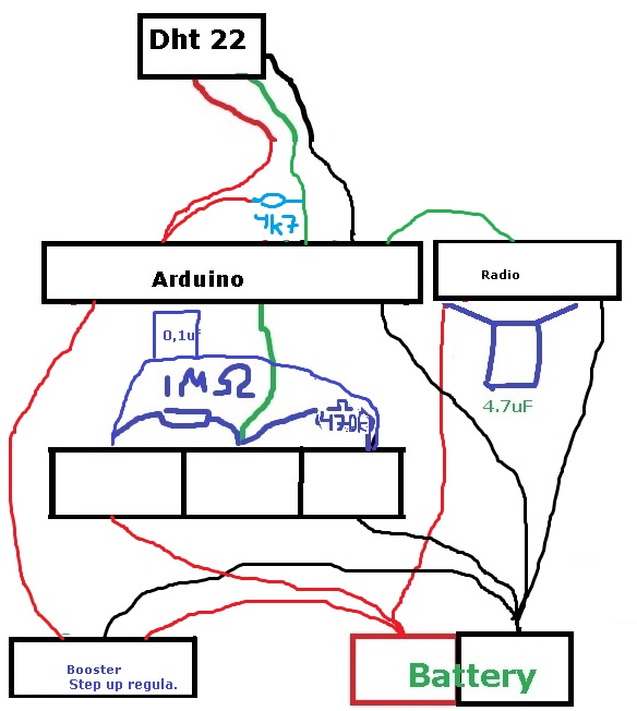
    This is also what im trying to do... have the same components/material as you and added the resistors for battery measurement. I dont get this long life (sleeps 15min, activated and sends).

    Can you post some sort of schematics or more detailed pictures so i can see your connections?
    Would be great!
    Here is my own try for a schematics:
    http://forum.mysensors.org/uploads/upload-5ed3f6ed-2d8c-4e6e-83bf-407973550c49.jpg


  • A tip for much better batterylife: burn a new bootloader for 1mhz. Now you can attach the arduino and nrf directly to the batteries and you can measure the battery with the Internal voltage meter of the 328p. If you use a dht you attach the step-up conv. And only attach the dht to it.


  • Hardware Contributor

    @sundberg84
    I've looked at your lovely drawing before and I don't see anything wrong with it except from that 0.1uF capacitor should be in parallell just with the 470k resistor, but it shouldn't matter regarding battery life time. What would be more interesting is to see your sketch. Or do you use the same as I do?

    A schematic and a few better pictures is on my to do list, but will probably come sooner now since you asked for it.


  • Hardware Contributor

    @m26872
    Pretty much the same, i have stolen majority of your code:
    Ive a array to get an average battery value each hour:

    #include <SPI.h>
    #include <MySensor.h>  
    #include <DHT.h>  
    
    //ställ in varje gång!=========================
    #define SketchName "Sovrum Uppe"
    #define SketchVer "1.0"
    #define NodeID 2
    #define VBAT_PER_BITS 0.003363075  // Calculated volts per bit from the used battery montoring voltage divider.   Internal_ref=1.1V, res=10bit=2^10-1=1023, Eg for 3V (2AA): Vin/Vb=R1/(R1+R2)=470e3/(1e6+470e3),  Vlim=Vb/Vin*1.1=3.44V, Volts per bit = Vlim/1023= 0.003363075
    #define VMIN 1.9  // Battery monitor lower level. Vmin_radio=1.9V
    #define VMAX 3.3  //  " " " high level. Vmin<Vmax<=3.44
    #define CHILD_ID_HUM 0
    #define CHILD_ID_TEMP 1
    #define HUMIDITY_SENSOR_DIGITAL_PIN 3
    int BATTERY_SENSE_PIN = A0;  // select the input pin for the battery sense point
    unsigned long SLEEP_TIME = 15*60000;
    //unsigned long SLEEP_TIME = 5000; //debug
    //Ställ även in gw.begin(,,,)
    //ställ in varje gång!=========================
    
    float lastTemp;
    float lastHum;
    boolean metric = true; 
    int batteryPcnt = 0;
    int batLoop = 0;
    int batArray[3];
    
    MySensor gw;
    DHT dht;
    
    MyMessage msgHum(CHILD_ID_HUM, V_HUM);
    MyMessage msgTemp(CHILD_ID_TEMP, V_TEMP);
    
    void setup()  
    { 
    // use the 1.1 V internal reference
      analogReference(INTERNAL);
      delay(500); // Allow time for radio if power used as reset <<<<<<<<<<<<<< Experimented with good result 
       
      gw.begin(NULL, NodeID, false);
    //incomingMessageCallback - Callback function for incoming messages from other nodes or controller and request responses. Default is NULL.
    //nodeId - The unique id (1-254) for this sensor. Default is AUTO(255) which means sensor tries to fetch an id from controller.
    //repeaterMode - Activate repeater mode. This node will forward messages to other nodes in the radio network. Make sure to call process() regularly. Default in false
      
      dht.setup(HUMIDITY_SENSOR_DIGITAL_PIN); 
    
      // Send the Sketch Version Information to the Gateway
      gw.sendSketchInfo(SketchName, SketchVer);
    
      // Register all sensors to gw (they will be created as child devices)
      gw.present(CHILD_ID_HUM, S_HUM);
      gw.present(CHILD_ID_TEMP, S_TEMP);
      
      metric = gw.getConfig().isMetric;
    }
    
    void loop()      
    {  
      int sensorValue = analogRead(BATTERY_SENSE_PIN);    // Battery monitoring reading
    delay(1000);
      delay(dht.getMinimumSamplingPeriod());
    
     
      float temperature = dht.getTemperature();
      Serial.print("Temp: "); Serial.print(temperature); Serial.println(" C");
      
     if (temperature > 0) {
       gw.send(msgTemp.set(temperature, 1));
      }
     
    delay(1000);
     
      float humidity = dht.getHumidity();
      Serial.print("Hum: "); Serial.print(humidity); Serial.println(" %");
       
       if (humidity > 0) {
        gw.send(msgHum.set(humidity, 1));
    }
    
    delay(1000);
       
       float Vbat  = sensorValue * VBAT_PER_BITS;
       int batteryPcnt = static_cast<int>(((Vbat-VMIN)/(VMAX-VMIN))*100.);   
     Serial.print("Battery percent: "); Serial.print(batteryPcnt); Serial.println(" %");  
       batArray[batLoop] = batteryPcnt;
      
       if (batLoop > 2) {
         
         batteryPcnt = (batArray[0] + batArray[1] + batArray[2] + batArray[3]);
         batteryPcnt = batteryPcnt / 4;
        Serial.print("Battery percent (Avg (4):) "); Serial.print(batteryPcnt); Serial.println(" %");
    
           gw.sendBatteryLevel(batteryPcnt);
           batLoop = 0;   
         }
         else 
         {
         batLoop = batLoop + 1;
         }
       
      gw.sleep(SLEEP_TIME); //sleep a bit
    }
    

  • Hardware Contributor

    @Sweebee
    It's already been discussed earlier in this thread (see EasyIoTs posts above), it's nevertheless a very good tip. I also have some test nodes running, but I consider it to be the next step from the "basic" design which was this threads concept. If I'll post something with this low-power-tweaked design it'll therefore be in a new thread. I should probably write something about this as an update in the first post...


  • Hardware Contributor

    @sundberg84
    I'm no code expert, and the only thing I can think of is that your "delay(1000)" will keep the power hungry radio awake. If you need delays (apart from debug) I'd prefer sleep instead. What's your battery life time look like?


  • Hardware Contributor

    UPDATE
    I've updated the first post with

    • A wiring layout.
    • Added a text about the low-power option
    • A few minor details.

  • Hardware Contributor

    Great layout/way to show your project - really nice!

    Its exactly as I do it so im getting a bit jealus here... . One node is down after a week.
    It might be the hardware or me not so good soldering so i short something out.

    I will try some more nodes now you have comfirmed I do it the right way and that should work.

    @m26872
    Thank you!


  • Hardware Contributor

    @sundberg84
    Thx, good you liked it.
    With such fast battery drain it should be easier to trace the current draw. First you'll need to measure the current. Second option is of course the good old switch-and-replace troubleshooting method.
    I've read about hardware and quality issues, but let's hope it isn't...


  • Hardware Contributor

    @m26872 What kind of pro-mini do you use?
    Im using deek robot 3.3v 8mhz and it seems like there is a problem with this: (http://forum.mysensors.org/topic/230/power-conservation-with-battery-powered-sensors) i kill them when i try to remove voltage regulator so i guess i havent suceeded yet with that.

    I dont have any good equipment to measure current... Ill have made a new sensor today - lets see how it operates.


  • Hardware Contributor

    Here are some close-up pictures of my Node 105 (which I opened with maximum care not to spoil my long term testing)
    1_IMG_1694.JPG
    2_IMG_1685.JPG
    3_IMG_1687.JPG
    4_IMG_1688.JPG
    5_IMG_1689.JPG
    6_IMG_1691.JPG
    7_IMG_1686.JPG
    8_IMG_1692.JPG
    9_IMG_1693.JPG


  • Admin

    Node 105 starts to become famous here 🙂
    We all follow him(?) with great excitement.


  • Hero Member

    yes, @m26872 any news ?


  • Hardware Contributor

    The news is that my Vera Lite gave up (soft-wise) after all hacking, plug-ins and un-clean factory resets, so I gave up on her (and Z-wave too, at least for a while). We've been fighting with each other for too long, so I'd say the divorce was welcome.

    Instead, in the controller jungle I decided to try Fhem, aware of the challanges as I'm not German- (nor Perl) speaking. I'm still in the sens-but-no-control-phase and have a few test nodes running, including "the" node 105. (Very easy transition btw, just one press at reset button then a node is in production with a new controller.)

    Back home today after 2w holiday I think it's looking good. The only problem now is of course that my trending is broken. If anyone knows how to merge the old trend data with the new, you're very welcome? Or just on how to rescue the Datamine data (from NAS)? If possible? I haven't researched anything yet.
    fhem_2w.PNG


  • Just an idea... I'm not sure if someone mentioned it:
    If sending consumes so much power... what about collecting sensor data every 5 minutes and then send the data (array) once per hour? Of course there would be some time calculating before logging in the controller (fhem), but this way, I can save power... What do you think?


  • Hardware Contributor

    @Meister_Petz Kind of what I already do in the test nodes 105/106 if you look at code above. Update frequencey and battery life time is a balance that can be adjusted just as you wish. Right now these node send update every 15 min and take sample for calculation 5 min before, which is about what I need. If you and your application is more interested in trending, history and data collection, I think your suggestion is excellent. If you need a fast response or action from your automation system it's not.

    But, what I think is most unneseccary with my test nodes 105/106 is that they check battery level every 15 min and send update if it has changed. Since the level typically is unstable right after the first transmission, it will generate a lot of useless transmissions. The only reason for me not to update code in node 105/106 is to keep it as an untouched study case. In my new nodes I usually set a fixed battery check/update frequency (1/week) which also works as a heartbeat signal for less active nodes.


  • Contest Winner

    Not sure if any one has had the same question. But the other day I stumbled on this little thing 😉
    https://www.adafruit.com/product/1572 It's a really small rechargeable battery. Now I don't no much about batteries. But I know that my LiOn powerd handdrill is very strong. The batteries of my handdril hardly lose power over time.

    So I was wondering if this could be used to power an Arduino and some sensors and how long it will take for the battery te become empty. It would make my 3.3V Sensors really small. I could almost install them in a small matchbox. Which I think is really cool!


  • Hardware Contributor

    @TheoL There are endless discussions about different batteries in the forum. Just search and read. I recall one issue with LiXx batteries is that max voltage is too high for the NRF24L01+ radio.


  • Ok, another thing: why not sending everything at once?

    As I understand you are using FHEM which allows a lot of coding on the controller side. So you could send batteryLevel, humidity and temperature in one go.

    Something like (this is no real code, just an idea):
    theValues = "battlvl:hum:temp"
    gw.send(msgAll.set(theValues, 1));

    and in fhem you split it at ":"

    So you have just one instead of 3 transmits.


  • Hardware Contributor

    @Meister_Petz I think it's a very good idea! It would be a nice option to have. Parsing with Perl should be simple even for a beginner like me, but to change the Mysensors core and fhem plugin is far beyond what I can. If you can do it, just go ahead and plz share.


  • ok, I did some testing and succeeded:

    This is the important part of the Arduino code:

    String allSens = String(sensor1) + " " + String(sensor2);
    gw.send(msg1.set(allSens.c_str()));
    

    This is the FHEM code:

    define Sensor MYSENSORS_DEVICE 20
    attr Sensor IODev MSGateway
    attr Sensor mapReading_brightness1 1 brightness
    attr Sensor mode node
    attr Sensor version 1.5
    attr Sensor userReadings Bat Deg
    
    # split and copy to userReadings
    define Sensor.copy at +*00:02:00 {my $a = ReadingsVal("Sensor","brightness1",1);; my @b = split(/\ /,$a);; fhem("setreading Sensor Bat $b[0]");; fhem("setreading Sensor Grad $b[1]");;}
    

    P.S.: when I had this in fhem.cfg I had to use @@ instead of only one @

    This is my complete Arduino code for a Battery Sensor with Dallas Temp:

      
    #include <MySensor.h>
    #include <SPI.h>
    
    #define SketchName "Sensor-send-all"
    #define SketchVer "1.2"
    #define NodeID 20
    
    unsigned long SleepTime = 828523; // 55234 = 1 Minute --- 828523 = 15 Minuten
      
    MySensor gw;
    
    // this is the one which sends everything
    #define SENSOR1_ID 1 // Sensor 1 - allAtOnceMessage
        
      //------------------------------------------------
      // Sensor PINS 
        #define SENSOR1_PIN  A0 // BattLevel
        #define SENSOR2_PIN  6  // Dallas
          
      // MyMessage V_TEMP, V_LIGHT_LEVEL, ... depending on Sensor Type
         MyMessage msg1(SENSOR1_ID,V_LIGHT_LEVEL); // Sensor 5 - allAtOnceMessage
    
      //------------------------------------------------
      // Dallas Temp
         #include <OneWire.h>
         #include <DallasTemperature.h>      
         OneWire oneWire(SENSOR2_PIN);
         DallasTemperature sensors(&oneWire);
         boolean receivedConfig = false;
             
         float firstRun = 1;
         boolean metric = true;
      
    void setup()  
      {  
        // use the 1.1 V internal reference
        analogReference(INTERNAL);
        delay(500); // Allow time for radio if power used as reset <<<<<<<<<<<<<< Experimented with good result 
      
        gw.begin(NULL, NodeID, false);
      
        // Send the sketch version information to the gateway and Controller
        gw.sendSketchInfo(SketchName, SketchVer);
            
        // present all Sensors to Gateway - S_TEMP, S_LIGHT_LEVEL,... depending an SENSOR type
        gw.present(SENSOR1_ID, S_LIGHT_LEVEL);     
            
        sensors.begin();  
      }
      
      
    void loop() 
      {
        gw.process();
    
           // wait some time to get all parts powered up
           if (firstRun == 1){
              delay(5000);
              firstRun = 0;
           } else {
              delay(1000);
           }
           
           //----------------------
           // Sensor1 - Battery Voltage - Part 1
              int sensorRead10 = analogRead(SENSOR1_PIN); 
    
           //----------------------
           // Sensor2 - DAL
             sensors.requestTemperatures();
             int16_t conversionTime = sensors.millisToWaitForConversion(sensors.getResolution());
             gw.sleep(conversionTime);
             float sensorRead2 = static_cast<float>(static_cast<int>((metric?sensors.getTempCByIndex(0):sensors.getTempFByIndex(0)) * 10.)) / 10.;
    
           //----------------------
           // Sensor1 - Battery Voltage - Part 2
              int sensorRead11 = analogRead(SENSOR1_PIN);
              //Volt der Battery
              
              float sensorRead1 = (sensorRead10 + sensorRead11 + sensorRead12) / 3 * 0.0033;  // should be 0.003363075 my Batteries are different
              float test = sensorRead10;
    
    
           //----------------------
           // send all to fhem
              String allComb = String(sensorRead1) + " " + String(sensorRead2);
              gw.send(msg1.set(allComb.c_str()));
    
          gw.sleep(SleepTime);
      } 


  • Hardware Contributor

    @Meister_Petz Wow! Well done! I think this can be very useful.
    In theory some power should be saved. Estimation from here is that a 250kbit/s transmission of a maximum size (32 byte) packet is >1.5ms. I think at around 20mA. Massage header is 7 byte, but a normal massage just a few bytes, i.e. just 30% of a message. Startup time for radio is fast (140us), so that shouldn't be an issue. (A side note here is that wake up atmega328p from sleep takes long (6ms?).)

    Is there a reason that you wrote the Fhem sonsor.copy macro as an "at" and not a "notify" ? The intuitive way would be to copy upon a new reading.


  • @m26872 there is no special reason for "at"... I think I got it from some where and it worked 😉


  • Hardware Contributor

    Soon 11 months of production including a fair amount of too frequent battery uppdates. Most exciting is wheter the initially used batteries in 106 will make it 12 months or not.
    Node105_20151002.PNG
    Node106_20151002.PNG


  • Contest Winner

    @m26872 perhaps you could reduce the redundant updates by filtering. If the current sample is lower than the "next" sample ignore it. If your node does not support charging, it will never really truly read an increase in battery voltage.


  • Hardware Contributor

    @Anticimex Yes, but in this particular case its double. Conclusion from above was that frequency and magnitude of the "low spikes" gives you information of how near the end you are. On the other hand I would never run like this if it wasn't for keeping the experiment "untouched". I think my thought for future sensors is to preserve that information, but save battery, just by reducing the number of samples.

    I'm still not sure of the best filter/algorithm to predict battery end of life from present and historic data. It will probably differ a lot wheter there's a step-up or a nicer load.


  • Mod

    @m26872 Just a suggestion: once the node dies you could take the raw data and run some filtering on it like @Anticimex suggested.
    It'll give you a quick way to experiment with different filter settings.
    Once you find an optimal filter you can implement it in the node(s).


  • Hardware Contributor

    @Yveaux You're right. I expect a good correlation between "spike depth" and the load profile just prior to sample. By controling this it should be quite repeatable.


  • This post is deleted!

  • Hardware Contributor

    @mntlvr Interesting discussion but why in this thread?


  • This post is deleted!

  • Hardware Contributor

    i think it would be better to open a new thread for this, instead to discuss two topics in one thread....the 2xaa battery sensor is very interesting 😉


  • Hardware Contributor

    The 12 months target was done a few days ago. Today's status 105: 63% and 106: 27%
    I had a thought to celebrate their birthday by retrieve old Vera data and make nice plot, but that has to wait. Next, 18 months.

    Just to clarify that these are no "sleeping" nodes; they transmit 100-150 messages each every day.


  • Hardware Contributor

    Battery level status report after 18 months:
    Node 105: 51%
    Node 106 (with used batteries): Died early January.

    Next 24 months.


  • Hey @m26872 Congrats on the testing and results! Looks great! I was wondering if I could get your feedback on something. I'm trying to build a very low powered ( 2 x AA ) Battery powered 3 in 1 sensor. ( Platform is a Pro Mini 8Mhz, 3.3v, with an PIR HC-SR501, NRF24L01, and a DHT 11 Temp and Hum sensor. The sensor should also report battery power periodically ideally using the vcc library ( not implemented yet ). Because these components use power hungry devices ( PIR, DHT ), I have already moded the PIR to work at 3.3, and have removed the regulator / LED from the pro mini. Would it make sense to use a step up / down regulator, or power directly from the VCC pin? I can't decide what would be more effective in prolonging battery life? Also, in terms of reporting battery state. I'm not sure what would be best also, hence the question around the VCC library?

    Below is my sketch. It is really taken from various posts on this forum and stitched together. If you could have a peak at it, and see if it is "optimal", as I don't believe it is today. ie: Perhaps I could only report temp / hum if it changes +/- a degree? Or send everything in a single radio announcement, then "Deep Sleep"? Lots of questions, and of course I am sure there are lots of answers. I'm just trying to build the most optimal battery efficient ( 2 x AA ) powered sensor no problem right! 🙂 Below is my current code:

     #define MY_GW_ID 31
    // Enable debug prints
    #define MY_DEBUG
    
    // Enable and select radio type attached
    #define MY_RADIO_NRF24
    //#define MY_RADIO_RFM69
    
    #include <SPI.h>
    #include <MySensor.h>  
    #include <DHT.h>  
    
    int BATTERY_SENSE_PIN = A0;  // select the input pin for the battery sense point
    
    //Constants
    #define SKETCH_NAME           "3 in 1 Sensor"
    #define SKETCH_VERSION        "1.0"
    #define CHILD_ID_HUM 0                    // Child id for Humidity
    #define CHILD_ID_TEMP 1                   // Child id for Temperature
    #define CHILD_ID_MOT 2                   // Id of the sensor child
    #define HUMIDITY_SENSOR_DIGITAL_PIN 7    // Where is my DHT22 data pin connected to
    #define DIGITAL_INPUT_SENSOR 3           // The digital input you attached your motion sensor.  (Only 2 and 3 generates interrupt!)
    #define INTERRUPT DIGITAL_INPUT_SENSOR-2 // Usually the interrupt = pin -2 (on uno/nano anyway)
    
    //Misc. variables
    uint8_t switchState = 2;
    unsigned long SLEEP_TIME = 820000;      // Sleep time between reads (in milliseconds) (close to 15')
    unsigned long SLEEP_TIME2 = 275000;     // Sleep time after int. (in milliseconds) (close to 5')
    uint8_t cycleInProgress = 0;
    uint8_t firstReportDone = 0;
    uint8_t firstReportWithZeroDone = 0;
    int oldBatteryPcnt = 0;
    
    MySensor gw;
    DHT dht;
    float lastTemp = 0 ;
    float lastHum = 0 ;
    boolean lastTripped = false ;
    boolean metric = true; 
    MyMessage msgHum(CHILD_ID_HUM, V_HUM);
    MyMessage msgTemp(CHILD_ID_TEMP, V_TEMP);
    MyMessage msgMot(CHILD_ID_MOT, V_TRIPPED);
    
    void setup()  
    { 
       // use the 1.1 V internal reference
    #if defined(__AVR_ATmega2560__)
       analogReference(INTERNAL1V1);
    #else
       analogReference(INTERNAL);
    #endif
      gw.begin();
      dht.setup(HUMIDITY_SENSOR_DIGITAL_PIN); 
    
      // Send the Sketch Version Information to the Gateway
      gw.sendSketchInfo("3 in 1 Sensor", "1.0");
    
    
     pinMode(DIGITAL_INPUT_SENSOR, INPUT);      // sets the motion sensor digital pin as input
     
      // Register all sensors to gw (they will be created as child devices)
      gw.present(CHILD_ID_HUM, S_HUM);
      gw.present(CHILD_ID_TEMP, S_TEMP);
      gw.present(CHILD_ID_MOT, S_MOTION);
       
      metric = gw.getConfig().isMetric;
    }
    
    void loop()      
    
    {  
    
       delay(dht.getMinimumSamplingPeriod());
    
      float temperature = dht.getTemperature();
      float humidity = dht.getHumidity();
      
      if (isnan(temperature)) {
          Serial.println("Failed reading temperature from DHT");
      } else if (temperature != lastTemp) {
        lastTemp = temperature;
        if (!metric) {
          temperature = dht.toFahrenheit(temperature);
        }
        gw.send(msgTemp.set(temperature, 1));
        Serial.print("T: ");
        Serial.println(temperature);
      }
      
      if (isnan(humidity)) {
          Serial.println("Failed reading humidity from DHT");
      } else if (humidity != lastHum) {
          lastHum = humidity;
          gw.send(msgHum.set(humidity, 1));
          Serial.print("H: ");
          Serial.println(humidity);
      }
      
      // get the battery Voltage
       int sensorValue = analogRead(BATTERY_SENSE_PIN);
       #ifdef DEBUG
       Serial.println(sensorValue);
       #endif
       
       // 1M, 470K divider across battery and using internal ADC ref of 1.1V
       // Sense point is bypassed with 0.1 uF cap to reduce noise at that point
       // ((1e6+470e3)/470e3)*1.1 = Vmax = 3.44 Volts
       // 3.44/1023 = Volts per bit = 0.003363075
       float batteryV  = sensorValue * 0.003363075;
       int batteryPcnt = sensorValue / 10;
    
       #ifdef DEBUG
       Serial.print("Battery Voltage: ");
       Serial.print(batteryV);
       Serial.println(" V");
    
       Serial.print("Battery percent: ");
       Serial.print(batteryPcnt);
       Serial.println(" %");
       #endif
    
      // Read digital motion value
      boolean tripped = digitalRead(DIGITAL_INPUT_SENSOR) == HIGH; 
      
      if (tripped != lastTripped ) {      
        Serial.println(tripped);
        gw.send(msgMot.set(tripped?"1":"0"));  // Send tripped value to gw 
      }
      
       if (oldBatteryPcnt != batteryPcnt) {
         // Power up radio after sleep
         gw.sendBatteryLevel(batteryPcnt);
         oldBatteryPcnt = batteryPcnt;
       }
      
      // Sleep until interrupt comes in on motion sensor. Send update every two minute. 
      gw.sleep(INTERRUPT, CHANGE, 0 );
    }
    

    thanks very much!


  • Hero Member

    @rhuehn It looks like you are repeating the conversation in this thread. Its better to continue the discussion there.


  • Mod

    I agree with AWI, but would like to add one thing: By using the DHT11 you are really fighting an uphill battle. There are several sensors that are more suitable for battery-powered sensors. See the study referenced by @AWI in https://forum.mysensors.org/topic/3801/witch-temp-hum-sensor-is-best-to-use-for-battery-powered-sensors/2


  • Thanks @mfalkvidd Starting to realize that..... I might swap to the HTU21D, but keep in mind I'm also using a PIR..... Is there a reliable, low voltage PIR sensor that works well? I haven't seen one yet ( 2 x AA BATT's, under 2.8 V )?

    Thanks


  • I have updated the original post if anyone can offer any suggestions. it is located Here

    Any feedback is greatly appreciated


  • @EasyIoT , how are your sensors doing, its been 2 years 🙂
    And also, @m26872 , the node 105. Is it alive?


  • Hardware Contributor

    @Nicklas-Starkel I've been busy for few months moving to a new house and have had my sensor network offline until now because of this. Node 105 was kept on and handled with care, but I was pretty sure it would be dead when I started my gateway yesterday. BUT, it was ALIVE ?! at 14% battery level. Amazing! 24 months with such poor and simple hardware and software. ❗ 💕 ⭐ 🎵 👯 👏 💪 Same batteries and only one restart (due to my controller change last year).
    One little remark though, it doesn't seem to send temperature och pressure, only humidity and battery level. Maybe an issue of voltage recovery time between transmissions.


  • Hardware Contributor

    This post is deleted!

  • Hardware Contributor

    Sorry for the noob question...
    I would re-create your setup. At which point of it you insert the multimeter to measure the current?

    Is it ok to "interrupt" the ground (proximity to the step up) and measure the current there?

    Thank you


  • Hardware Contributor

    @sineverba Just cut one of the battery wires of the finished assembly. Solder together again when your done measuring.


  • Has anyone got a V2 version working for this?


  • @palmerfarmer said in My 2AA battery sensor:

    Has anyone got a V2 version working for this?

    Do you mean running with MySensors 2.3?


  • Any Ver 2.xx,
    So I have cobbled together/hacked this and it seem to work, battery has stayed at 97% for 2 weeks now. Feel free to Hack about and improve i have this mounted on an easyPCB board, x2AA batteries, NRF radio, BME280 with a 3.3v convertor .

    /*   
    * use mysensors library 2.2.0
    * ALL WORKING AND TESTED ON EASY PCB BOARD WITH BATTERY SAVING CODE 29/11/18
    *
    * Time SET to 15 mins
    * also added BME280.writeMode (smSleep); to reduce quisecent to current to 40uA
    * BME280 sensor connections: 3.3v, 0V, SCL to A5, SDA to A4, BAT to A0
    **/
    
    //Enable debug prints to serial monitor
    #define MY_DEBUG 
    
    // Enable and select radio type attached
    #define MY_RADIO_NRF24
    #define MY_RF24_PA_LEVEL RF24_PA_MIN //settings are MIN, LOW, HIGH, MAX
    #define MY_NODE_ID 18
    //#define MY_RADIO_RFM69
    
    #include <SPI.h>
    #include <MySensors.h>  
    #include <Wire.h>
    #include <BME280_MOD-1022.h>
    
    // BME280 libraries and variables
    // Bosch BME280 Embedded Adventures MOD-1022 weather multi-sensor Arduino code
    // Written originally by Embedded Adventures
    // https://github.com/embeddedadventures/BME280
    
    
    #define BARO_CHILD 0
    #define TEMP_CHILD 1
    #define HUM_CHILD 2
    
    
    int BATTERY_SENSE_PIN = A0;  // select the input pin for the battery sense point
    
    unsigned long SLEEP_TIME = 15*60000;  // sleep time between reads (seconds x*1000 milliseconds)
    //unsigned long SLEEP_TIME = 20000;  // Debug test time 20 seconds
    int oldBatteryPcnt = 0;
    
        
    long interval = 1000;                // 1 min interval at which to send (milliseconds)
    long previousMillis = interval;        // will store last time data was sent
    
    const float ALTITUDE = 0; // <-- adapt this value to your location's altitude (in m). Use your smartphone GPS to get an accurate value!
    
    const char *weather[] = { "stable", "sunny", "cloudy", "unstable", "thunderstorm", "unknown" };
    enum FORECAST
    {
      STABLE = 0,     // "Stable Weather Pattern"
      SUNNY = 1,      // "Slowly rising Good Weather", "Clear/Sunny "
      CLOUDY = 2,     // "Slowly falling L-Pressure ", "Cloudy/Rain "
      UNSTABLE = 3,   // "Quickly rising H-Press",     "Not Stable"
      THUNDERSTORM = 4, // "Quickly falling L-Press",    "Thunderstorm"
      UNKNOWN = 5     // "Unknown (More Time needed)
    };
    
    
    const int LAST_SAMPLES_COUNT = 5;
    float lastPressureSamples[LAST_SAMPLES_COUNT];
    
    
    // this CONVERSION_FACTOR is used to convert from Pa to kPa in the forecast algorithm
    // get kPa/h by dividing hPa by 10 
    #define CONVERSION_FACTOR (1.0/10.0)
    
    int minuteCount = 0;
    bool firstRound = true;
    // average value is used in forecast algorithm.
    float pressureAvg;
    // average after 2 hours is used as reference value for the next iteration.
    float pressureAvg2;
    
    float dP_dt;
    boolean metric;
    MyMessage tempMsg(TEMP_CHILD, V_TEMP);
    MyMessage humMsg(HUM_CHILD, V_HUM);
    MyMessage pressureMsg(BARO_CHILD, V_PRESSURE);
    
    float getLastPressureSamplesAverage()
    {
      float lastPressureSamplesAverage = 0;
      for (int i = 0; i < LAST_SAMPLES_COUNT; i++)
      {
        lastPressureSamplesAverage += lastPressureSamples[i];
      }
      lastPressureSamplesAverage /= LAST_SAMPLES_COUNT;
    
      return lastPressureSamplesAverage;
    }
    
    
    // Algorithm found here
    // http://www.freescale.com/files/sensors/doc/app_note/AN3914.pdf
    // Pressure in hPa -->  forecast done by calculating kPa/h
    int sample(float pressure)
    {
      // Calculate the average of the last n minutes.
      int index = minuteCount % LAST_SAMPLES_COUNT;
      lastPressureSamples[index] = pressure;
    
      minuteCount++;
      if (minuteCount > 185)
      {
        minuteCount = 6;
      }
    
      if (minuteCount == 5)
      {
        pressureAvg = getLastPressureSamplesAverage();
      }
      else if (minuteCount == 35)
      {
        float lastPressureAvg = getLastPressureSamplesAverage();
        float change = (lastPressureAvg - pressureAvg) * CONVERSION_FACTOR;
        if (firstRound) // first time initial 3 hour
        {
          dP_dt = change * 2; // note this is for t = 0.5hour
        }
        else
        {
          dP_dt = change / 1.5; // divide by 1.5 as this is the difference in time from 0 value.
        }
      }
      else if (minuteCount == 65)
      {
        float lastPressureAvg = getLastPressureSamplesAverage();
        float change = (lastPressureAvg - pressureAvg) * CONVERSION_FACTOR;
        if (firstRound) //first time initial 3 hour
        {
          dP_dt = change; //note this is for t = 1 hour
        }
        else
        {
          dP_dt = change / 2; //divide by 2 as this is the difference in time from 0 value
        }
      }
      else if (minuteCount == 95)
      {
        float lastPressureAvg = getLastPressureSamplesAverage();
        float change = (lastPressureAvg - pressureAvg) * CONVERSION_FACTOR;
        if (firstRound) // first time initial 3 hour
        {
          dP_dt = change / 1.5; // note this is for t = 1.5 hour
        }
        else
        {
          dP_dt = change / 2.5; // divide by 2.5 as this is the difference in time from 0 value
        }
      }
      else if (minuteCount == 125)
      {
        float lastPressureAvg = getLastPressureSamplesAverage();
        pressureAvg2 = lastPressureAvg; // store for later use.
        float change = (lastPressureAvg - pressureAvg) * CONVERSION_FACTOR;
        if (firstRound) // first time initial 3 hour
        {
          dP_dt = change / 2; // note this is for t = 2 hour
        }
        else
        {
          dP_dt = change / 3; // divide by 3 as this is the difference in time from 0 value
        }
      }
      else if (minuteCount == 155)
      {
        float lastPressureAvg = getLastPressureSamplesAverage();
        float change = (lastPressureAvg - pressureAvg) * CONVERSION_FACTOR;
        if (firstRound) // first time initial 3 hour
        {
          dP_dt = change / 2.5; // note this is for t = 2.5 hour
        }
        else
        {
          dP_dt = change / 3.5; // divide by 3.5 as this is the difference in time from 0 value
        }
      }
      else if (minuteCount == 185)
      {
        float lastPressureAvg = getLastPressureSamplesAverage();
        float change = (lastPressureAvg - pressureAvg) * CONVERSION_FACTOR;
        if (firstRound) // first time initial 3 hour
        {
          dP_dt = change / 3; // note this is for t = 3 hour
        }
        else
        {
          dP_dt = change / 4; // divide by 4 as this is the difference in time from 0 value
        }
        pressureAvg = pressureAvg2; // Equating the pressure at 0 to the pressure at 2 hour after 3 hours have past.
        firstRound = false; // flag to let you know that this is on the past 3 hour mark. Initialized to 0 outside main loop.
      }
    
      int forecast = UNKNOWN;
      if (minuteCount < 35 && firstRound) //if time is less than 35 min on the first 3 hour interval.
      {
        forecast = UNKNOWN;
      }
      else if (dP_dt < (-0.25))
      {
        forecast = THUNDERSTORM;
      }
      else if (dP_dt > 0.25)
      {
        forecast = UNSTABLE;
      }
      else if ((dP_dt > (-0.25)) && (dP_dt < (-0.05)))
      {
        forecast = CLOUDY;
      }
      else if ((dP_dt > 0.05) && (dP_dt < 0.25))
      {
        forecast = SUNNY;
      }
      else if ((dP_dt >(-0.05)) && (dP_dt < 0.05))
      {
        forecast = STABLE;
      }
      else
      {
        forecast = UNKNOWN;
      }
    
      return forecast;
    }


    void setup() 
    
    {
       // use the 1.1 V internal reference
    #if defined(__AVR_ATmega2560__)
       analogReference(INTERNAL1V1);
    #else
       analogReference(INTERNAL);
    #endif
    
      metric = getControllerConfig().isMetric;  // was getConfig().isMetric; before MySensors v2.1.1
      Wire.begin(); // Wire.begin(sda, scl)
      // use the 1.1 V internal reference
      #if defined(__AVR_ATmega2560__)
      analogReference(INTERNAL1V1);
      #else
      analogReference(INTERNAL);
      #endif
    }
    
    void presentation()  {
      // Send the sketch version information to the gateway and Controller
      sendSketchInfo("BME280_BAT_V2", "V2e.");
    
      // Register sensors to gw (they will be created as child devices)
      present(BARO_CHILD, S_BARO);
      present(TEMP_CHILD, S_TEMP);
      present(HUM_CHILD, S_HUM);
    
    }
    
    // Loop
    void loop() {
    
    {
       // get the battery Voltage
       int sensorValue = analogRead(BATTERY_SENSE_PIN);
       #ifdef MY_DEBUG
       Serial.println(sensorValue);
       #endif
    
       // 1M, 470K divider across battery and using internal ADC ref of 1.1V
       // Sense point is bypassed with 0.1 uF cap to reduce noise at that point
       // ((1e6+470e3)/470e3)*1.1 = Vmax = 3.44 Volts
       // 3.44/1023 = Volts per bit = 0.003363075
    
       int batteryPcnt = sensorValue / 10;
    
       #ifdef MY_DEBUG
       float batteryV  = sensorValue * 0.003363075;
       Serial.print("Battery Voltage: ");
       Serial.print(batteryV);
       Serial.println(" V");
    
       Serial.print("Battery percent: ");
       Serial.print(batteryPcnt);
       Serial.println(" %");
       #endif
    
       if (oldBatteryPcnt != batteryPcnt) {
         // Power up radio after sleep
         sendBatteryLevel(batteryPcnt);
         oldBatteryPcnt = batteryPcnt;
       }
     //  sleep(SLEEP_TIME);
    }
    
    
    unsigned long currentMillis = millis();  
    
    if(currentMillis - previousMillis > interval) {
        // save the last time sent the data
        previousMillis = currentMillis;
    
      analogReference(INTERNAL);
      wait(500);
      
      // need to read the NVM compensation parameters
      BME280.readCompensationParams();
    
      // Normal mode for regular automatic samples
      BME280.writeStandbyTime(tsb_0p5ms);         // tsb = 0.5ms
      BME280.writeFilterCoefficient(fc_16);       // IIR Filter coefficient 16
      BME280.writeOversamplingPressure(os16x);    // pressure x16
      BME280.writeOversamplingTemperature(os8x);  // temperature x8
      BME280.writeOversamplingHumidity(os8x);     // humidity x8
      
      BME280.writeMode(smNormal);
    
        // Just to be sure, wait until sensor is done mesuring  
        while (BME280.isMeasuring()) {
      }
    
      // Read out the data - must do this before calling the getxxxxx routines
      BME280.readMeasurements();
    
      float temperature = BME280.getTemperatureMostAccurate();                    // must get temp first
      float humidity = BME280.getHumidityMostAccurate();
      float pressure_local = BME280.getPressureMostAccurate();                    // Get pressure at current location
      float pressure = pressure_local/pow((1.0 - ( ALTITUDE / 44330.0 )), 5.255); // Adjust to sea level pressure using user altitude
      int forecast = sample(pressure);
    
      if (!metric) 
      {
        // Convert to fahrenheit
        temperature = temperature * 9.0 / 5.0 + 32.0;
      }
    //**/
      Serial.println();
      Serial.print("Temperature = ");
      Serial.print(temperature);
      Serial.println(metric ? " °C" : " °F");
      Serial.print("Humidity = ");
      Serial.print(humidity);
      Serial.println(" %");
      Serial.print("Pressure = ");
      Serial.print(pressure);
      Serial.println(" hPa");
      Serial.print("Forecast = ");
      Serial.println(weather[forecast]);
      Serial.println();
    //*/
    
        send(tempMsg.set(temperature, 1));
    wait(50);
        send(humMsg.set(humidity, 1));
    wait(50);
        send(pressureMsg.set(pressure, 2));
    wait(50);
    
    BME280.writeMode (smSleep);
    sleep(SLEEP_TIME);
    
    }
    
    }


  • 11months on battery at 87%... still working!0_1574260268012_BME280 battery.JPG


  • This post is deleted!


  • @palmerfarmer,

    That project box is perfect! Where did you find it (it doesn't look printed)?


  • I got it from CPC in the UK which are owned by Farnell
    https://cpc.farnell.com/hammond/1593qgy/case-with-bat-compart-110x66x28mm/dp/EN82140
    You may have to make a slight mod to the board or enclosure to make it fit.
    good luck


Log in to reply
 

Suggested Topics

  • 8
  • 2
  • 44
  • 29
  • 90
  • 1

0
Online

11.2k
Users

11.1k
Topics

112.5k
Posts