HELP!! NODE WITH RELAY VOLTAGE AND DETECTOR
-
Hi I'm trying to make a script of Arduino to create a node with home automation: relay, light sensor, and sensor noise.
The problem is that the only solution for the installation of the coupling relay with a switch.
The script should be divided into 2 sections:
- asynchronous control with photoresistor
- Turn off relay asynchronously, following a first draft to be modified:
int stato = statorelay[message.getBool()]; //leggo stato da array
Serial.print("stato:");
Serial.println(stato);
Serial.print("getbboolo:");
Serial.println(message.getBool());
Serial.print("messaggio sensore:");
Serial.println(message.sensor);
if (message.getBool()== 1, stato ==0) { // MESSAGGIO DI ACCENSIONE CON LAMPADINA SPENTA
Serial.print("ACCENDI RELAY - Lampanida accesa ");
digitalWrite(message.sensor-1+RELAY_3, RELAY_ON);
statorelay[message.getBool()] = 1; // salvo in memoria stato relay
return; // blocco script
}
if (message.getBool()== 0, stato ==1) { // MESSAGGIO DI SPEGNIMENTO CON LAMPADINA ACCESA
Serial.print("SPEGNI RELAY - Lampanida spenta");
digitalWrite(message.sensor-1+RELAY_3, RELAY_OFF);
statorelay[message.getBool()] = 0; // salvo in memoria stato relay
return;
}
if (message.getBool()== 0, stato ==0) { //MESSAGGIO DI SPEGNIMENTO CON LAMPADINA SPENTA
Serial.print("ACCENDI RELAY - Lampanida spenta ");
digitalWrite(message.sensor-1+RELAY_3, RELAY_ON);
statorelay[message.getBool()] = 1; // salvo in memoria stato relay
return;
}
if (message.getBool()== 1, stato ==1) { //MESSAGGIO DI ACCENSIONE CON LAMPADINA ACCESA
Serial.print("SPEGNI RELAY - Lampanida accesa ");
digitalWrite(message.sensor-1+RELAY_3, RELAY_OFF);
statorelay[message.getBool()] = 0; // salvo in memoria stato relay
return;
}I NEED HELP!!! THANK YOU!
If I was not clear please ask, sorry for my english
-
- I NEED HELP!!!! is not a question. Describe your problem and then we might be able to help.
- Please rewrite this sentence: "The problem is that the only solution for the installation of the coupling relay with a switch." I do not understand it at all. Better use google translate if your English is not so good.
- You wrote something about asynchronously, I do not see any interrupts so your code is fully synchronous.
OK, I rephrase the request.
I have at home this CONFIGURATION
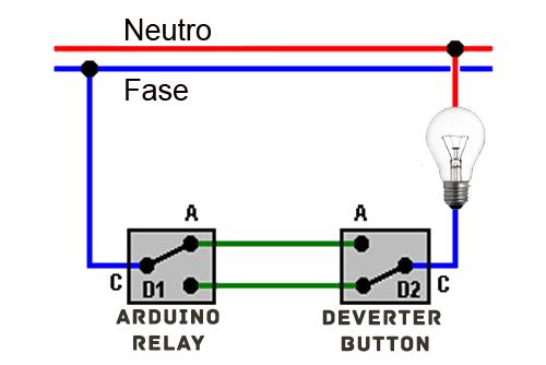
I created the following script:
// Enable debug prints to serial monitor
#define MY_DEBUG

// Enable and select radio type attached
#define MY_RADIO_NRF24
//#define MY_RADIO_RFM69

// Enabled repeater feature for this node
#define MY_REPEATER_FEATURE

#include <SPI.h>
#include <MySensors.h>


#define RELAY_PIN  3  // Arduino Digital I/O pin number for relay
#define BUTTON_PIN  4  // Arduino Digital I/O pin number for button
#define CHILD_ID 1   // Id of the sensor child
#define RELAY_ON 0
#define RELAY_OFF 1


  bool state;
  int luce;
  int soglia = 25; //  imposed sensor sensitivity
  int statorelay = 0; //  variable that saves in memory initial state relay

MyMessage msg(CHILD_ID,V_LIGHT);

void setup()
{


  pinMode(RELAY_PIN, OUTPUT); //
  digitalWrite(RELAY_PIN, RELAY_OFF); //  Initial setting relay on off


}

void presentation()  {

  sendSketchInfo("RELAY DEVERTER", "1.0");
  present(CHILD_ID, S_LIGHT);
}


void loop()
{

      int value;
      luce = (1023-analogRead(A0))/10.23;  //
I note if there is current on the bulb. I use a 220v led with a photoresistor.
      if(luce < soglia) {

        send(msg.set(value==HIGH ? 1 : 0)); //voltage yes
        }
      else {

        send(msg.set(value==LOW ? 1 : 0)); // voltage no
        }


      delay (1000);

}


void receive(const MyMessage &message) {
  //  SECTION ENTER POWER RELAY WITH REVERSE

     if (message.getBool()== 1, statorelay ==0)  {    // POWER ON MESSAGE WITH BULB OFF
              Serial.print("ACCENDI RELAY - Lampanida accesa ");
              digitalWrite(RELAY_PIN, RELAY_ON);
              statorelay=1; // salvo in memoria stato relay
              return; // blocco script
        }
     if (message.getBool()== 0, statorelay ==1)  {   //  SHUTDOWN WITH MESSAGE ON BULB
               Serial.print("SPEGNI RELAY - Lampanida spenta");
               digitalWrite(RELAY_PIN, RELAY_OFF);
               statorelay=0;
               return;
       }
     if (message.getBool()== 0, statorelay ==0)  {   // SHUTDOWN MESSAGE WITH BULB OFF - REVERSE
                 Serial.print("ACCENDI RELAY - Lampanida spenta ");
                 digitalWrite(RELAY_PIN, RELAY_ON);
                 statorelay=1;
                 return;
        }
     if (message.getBool()== 1, statorelay ==1)  {   //POWER ON MESSAGE WITH BULB ON - REVERSED
                   Serial.print("SPEGNI RELAY - Lampanida accesa ");
                   digitalWrite(RELAY_PIN, RELAY_OFF);
                   statorelay=1;
                   return;
        }
}
This script works, and allows me to see if the bulb is actually on or off, and turn it off or turn it on indipendetemente the state of the relay.
The problem is the script:
- I would like to add more relays with detectors.
- I would like to send the status of the bulb to the gateway only when actually changes.
Can you help me? I'VE BEEN CLEAR?
THANK YOU!!!
-
OK, I rephrase the request.
I have at home this CONFIGURATION
I created the following script:
// Enable debug prints to serial monitor
#define MY_DEBUG

// Enable and select radio type attached
#define MY_RADIO_NRF24
//#define MY_RADIO_RFM69

// Enabled repeater feature for this node
#define MY_REPEATER_FEATURE

#include <SPI.h>
#include <MySensors.h>


#define RELAY_PIN  3  // Arduino Digital I/O pin number for relay
#define BUTTON_PIN  4  // Arduino Digital I/O pin number for button
#define CHILD_ID 1   // Id of the sensor child
#define RELAY_ON 0
#define RELAY_OFF 1


  bool state;
  int luce;
  int soglia = 25; //  imposed sensor sensitivity
  int statorelay = 0; //  variable that saves in memory initial state relay

MyMessage msg(CHILD_ID,V_LIGHT);

void setup()
{


  pinMode(RELAY_PIN, OUTPUT); //
  digitalWrite(RELAY_PIN, RELAY_OFF); //  Initial setting relay on off


}

void presentation()  {

  sendSketchInfo("RELAY DEVERTER", "1.0");
  present(CHILD_ID, S_LIGHT);
}


void loop()
{

      int value;
      luce = (1023-analogRead(A0))/10.23;  //
I note if there is current on the bulb. I use a 220v led with a photoresistor.
      if(luce < soglia) {

        send(msg.set(value==HIGH ? 1 : 0)); //voltage yes
        }
      else {

        send(msg.set(value==LOW ? 1 : 0)); // voltage no
        }


      delay (1000);

}


void receive(const MyMessage &message) {
  //  SECTION ENTER POWER RELAY WITH REVERSE

     if (message.getBool()== 1, statorelay ==0)  {    // POWER ON MESSAGE WITH BULB OFF
              Serial.print("ACCENDI RELAY - Lampanida accesa ");
              digitalWrite(RELAY_PIN, RELAY_ON);
              statorelay=1; // salvo in memoria stato relay
              return; // blocco script
        }
     if (message.getBool()== 0, statorelay ==1)  {   //  SHUTDOWN WITH MESSAGE ON BULB
               Serial.print("SPEGNI RELAY - Lampanida spenta");
               digitalWrite(RELAY_PIN, RELAY_OFF);
               statorelay=0;
               return;
       }
     if (message.getBool()== 0, statorelay ==0)  {   // SHUTDOWN MESSAGE WITH BULB OFF - REVERSE
                 Serial.print("ACCENDI RELAY - Lampanida spenta ");
                 digitalWrite(RELAY_PIN, RELAY_ON);
                 statorelay=1;
                 return;
        }
     if (message.getBool()== 1, statorelay ==1)  {   //POWER ON MESSAGE WITH BULB ON - REVERSED
                   Serial.print("SPEGNI RELAY - Lampanida accesa ");
                   digitalWrite(RELAY_PIN, RELAY_OFF);
                   statorelay=1;
                   return;
        }
}
This script works, and allows me to see if the bulb is actually on or off, and turn it off or turn it on indipendetemente the state of the relay.
The problem is the script:
- I would like to add more relays with detectors.
- I would like to send the status of the bulb to the gateway only when actually changes.
Can you help me? I'VE BEEN CLEAR?
THANK YOU!!!
@Marco-Avallone Please use the code syntax for your code snipet. Like this it's very hard to read. Also why do you use caps so much?
For me your question isn't clear. What have you tried to actually do that did not work?- for 1: just add another child to your sketch for another relay... basically duplicate most of your code
- for 2: then safe the last state and check it before sending a message
Hope that helped.