Current Sensing?
-
No, you owe us all money! STAND BY YOUR BET! xD
I like it @scalz - you're approach is much better for low power modes, much better than mine. I see that the comparator is not needed for such application, i'm going that route because its the 'done' way. However, you're style is much better for battery powered nodes which will naturally attract people.
I'm really struggling to get to grips with KiCAD and i'm starting to give up after just one footprint. This thing would have been hours ago if i just used eagle.
The style is more 'inline' (not the technical term, but that is how i know it). What photodiode/resistor are you using? Most should pick up quite a decent range of wavelengths on the blinking LED.
-
thx guys :joy:
@Samuel235
in fact i'm jealous of you too as you're studying electronics, looks cool ;)
I've only designed the pcb for the moment, electronics in my thing is air wired, i don't remember how this soldering style is named??
so this looks like this
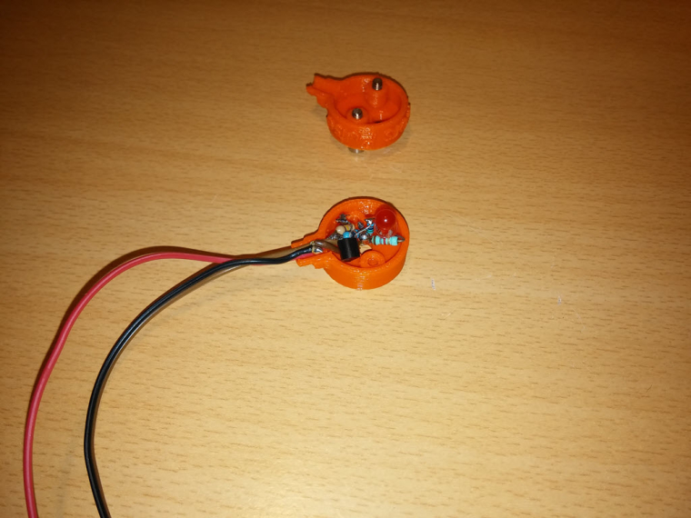
i'll check a few things for tomorrow, and also would like to try sensing a few others led colors and i'll post, no problem. I've been able to go up to 110hz though, then it was fluctuating too much (40hz was because i forgot to remove a capa on the signal generator side).@scalz - The general photodiode has a range of "Wavelength range (S10%) 400 nm to 1100 nm (SFH
213)", quoted from a datasheet here: http://www.osram-os.com/Graphics/XPic5/00101689_0.pdf. So this means that we should be good for a fair few different LED colours. -
@scalz - I wouldn't be jealous of me, my school is pretty bad to be honest with you. But it gets me a degree! I'm actually working/studying in the robotics field, so not just electronics :) We have a PCB router at school and I'm trying to get permission to use this for our projects here too, only for prototyping ofc. Finished boards will be ordered from a board house for a more professional feel, but it allows me to get an idea of the size of board we can get our designs down too and such.
I've also given up with KiCAD for now, it feels so unprofessional to get libraries and such made. Individual addons/programs inside of KiCAD to do different aspects just feels so clunky to me right now, eagle has my attention until i get my hands on solidworks PCB.
-
Here are the renders for my enclosure, will be printing in the morning and will report back with some more progress photos.
I did try to get the font into the same font as we use for the official logos of MySensors but the font really didn't correspond with solidworks, there are missing faces and lines all over the generated font and therefor it wasn't an option. If anyone knows a work around or something i could do to make it look remotely like the logo then please inform me. At some point i may attempt to put our little man logo on there instead of the opensource hardware logo, maybe.
I have designed the cable inlet with ethernet cable in mind, that may change too, not sure yet. I'm going for the cheap and locking/latching RJ45 rather than something that could slip out of socket as most of us use our electric cupboards for other uses as well such as cloakrooms for coats and such in the UK.
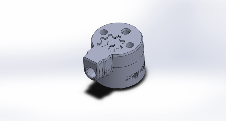

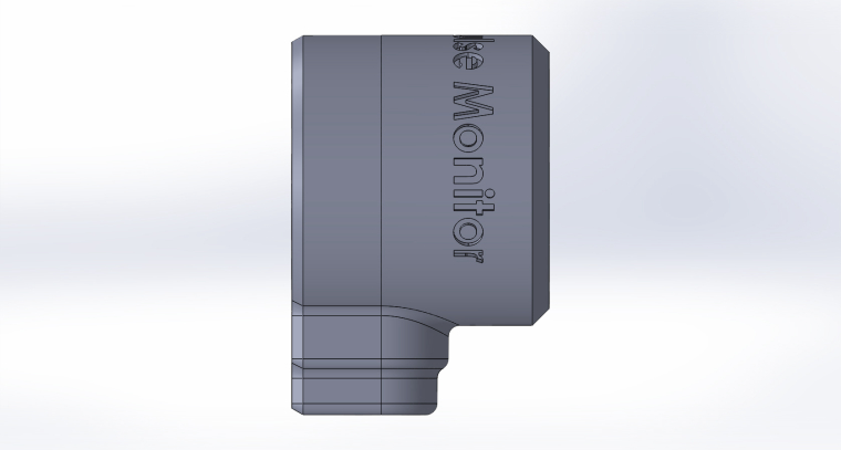
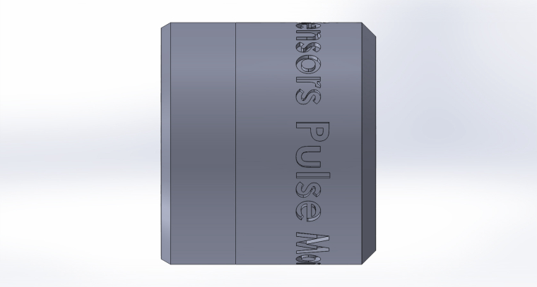
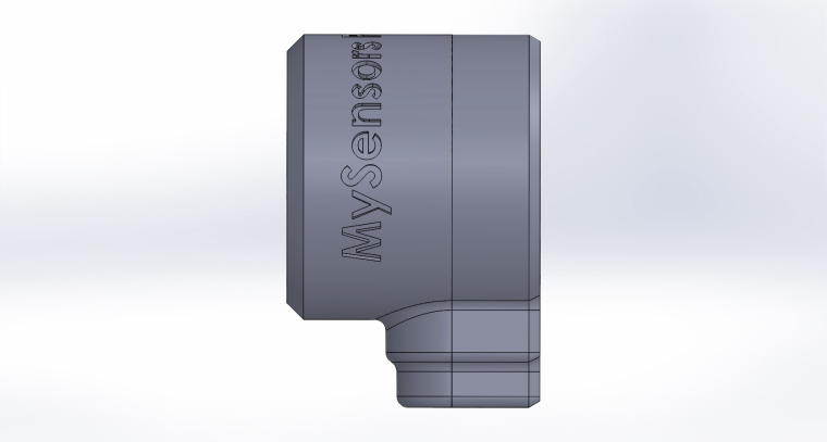
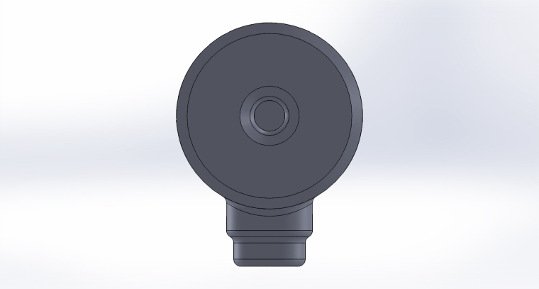
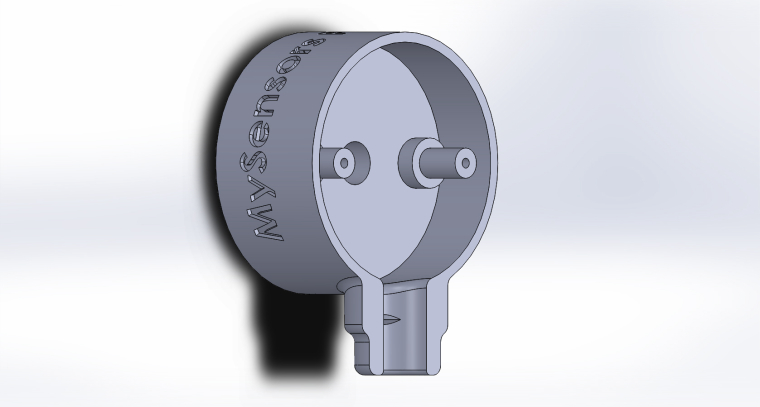
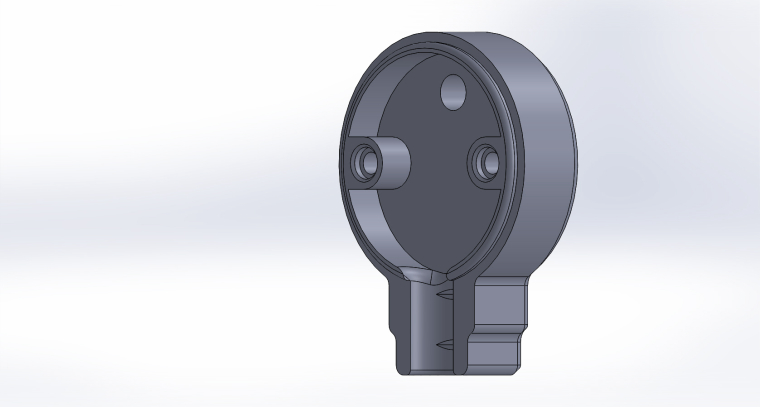
Would anyone like to see anything on here that i haven't thought about? I'm open to criticism.
-
cool
regarding your print, i think it's better to extrude the text, i'm not sure you'll get a good rendering like this..
same thing for the logo.. i guess you'll print it facing to the bed, maybe that won't look so great too. -
cool
regarding your print, i think it's better to extrude the text, i'm not sure you'll get a good rendering like this..
same thing for the logo.. i guess you'll print it facing to the bed, maybe that won't look so great too.@scalz - I'm not keen on the extruded text look tbh, i'm testing this format but my printer is pretty good with overhangs and thats why i'm taking my chance on the logo on top. It will be facing the bed and so we shall see how it turns out. Its not the end of the world if it doesn't look pretty straight away but i'm hoping its acceptable :)
-
i know for the extruded text, me too though. but i think it's more in general, 3d printing, it is more readable. but you can try, sure it won't take so much time and maybe that'll work, can't wait to see how it looks now ;)
-
i know for the extruded text, me too though. but i think it's more in general, 3d printing, it is more readable. but you can try, sure it won't take so much time and maybe that'll work, can't wait to see how it looks now ;)
-
These look great, I have been working on something similar, for now just using an LM393 module with a phototransistor (or it could be a photodiode, I'm not sure). Initial experiments with a light dependent resistor LM393 module were not successful, its ramp up time was too long for what turned out to be the 15ms pulse time on my electricity meter (3200 pulses per kWh).
At present I am just using Blu-Tack to provide light isolation (my meter is mounted outside on the front porch) but I was looking at a similar enclosure. I have ordered some Velcro dots off eBay for mounting and have been looking at some enclosures but the ones I see here look much better than anything I have found so far.
@Samuel235 with your design I was thinking it might make more sense mechanically if the wire is hanging down to have it exiting the enclosure as close as possible to the plane of the mounting point so that as much of the force it is exerting is as a shear which Velcro is good at holding.
I have also ordered some other parts to try replacing the LDR on my original LM393 module, based on a combination of local availability, price, and wavelength and angular sensitivity. The two I choose are the SFH213 photodiode (wide wavelength, 10º angular) and the SFH309 phototransistor (full spectrum, 24º angular). I'm just getting back into electronics after many years so I still have to pull out the soldering iron and get a workbench set up to try these out.
@mwalker - My design has the cable coming out where it does because that is where the PCB plane is. Mine is relatively thicker than @scalz's, not 100% sure the technical details of his but my detector is not right on the surface, it has a cavity to make it nice and dark for that sensor.
My design implements a LM393 and a photodiode, which i'm sure you already know, is designed for high speed detections and fast saturation of the diode and fast release back to normal. However, my meter is not one that blinks fast (i think) and i don't have a signal generator at the moment so i wouldn't be able to test down to that speed. The photodiode has an effective window shown below:
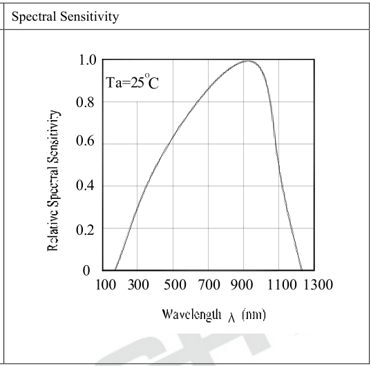
So, i think that my design may suit your use, lets see :)
-
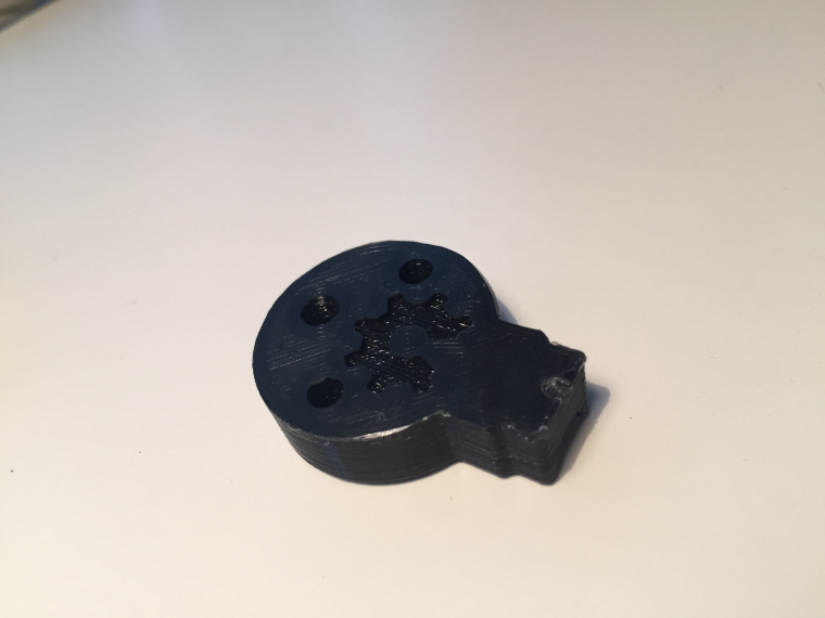
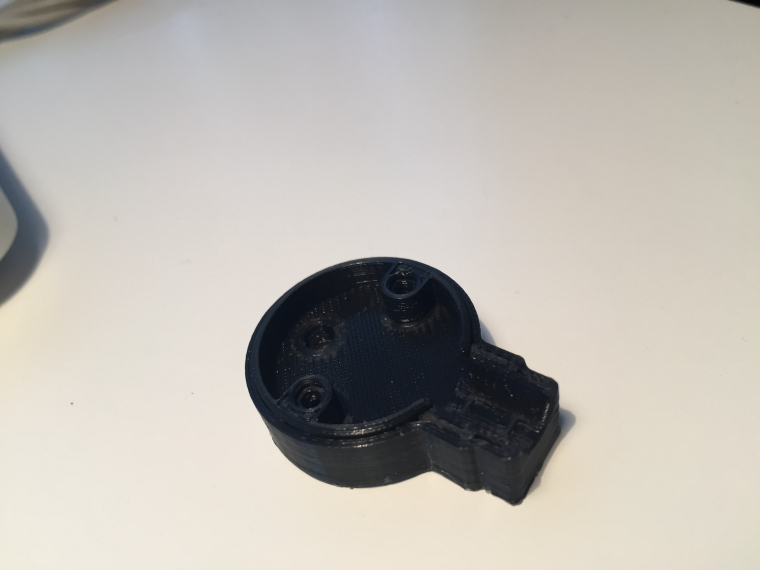
I'm pretty impressed with how it handeling that overhang on the logo considering there wasn't much vertical space under it to the bed i expected it to droop down to the bed. I like it! Ignore the little cunk out at the cable entry part, my glue held it too hard on the bed. The cable grip is a little too small, reprinting it with a more pronounced grip now (Didn't want it too large as it would damage the cable, but its not enough at the moment).
-
it didn't slice the text??
-
It looks good @Samuel235, having the detector recessed in a cavity in order to reduce the impact of ambient light isn't something that I had considered, I guess because I was mainly thinking about an off the shelf enclosure, or repurposing some other type of container, i.e. this, but I like these designs a lot better.
I was able to use a cheap logic analyser with sigrok to work out the pulse time on my meter, and I am in the midst of designing a test rig using WS2812 led strip and a separate microcontroller in order to be able to test my pulse detection code when more of the LM393 modules arrive. One location I need to use this system has ten meters, and another has nine meters, so I need to have a good test rig to make sure that my system won't be dropping pulses.
-
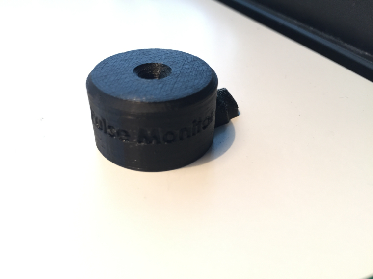
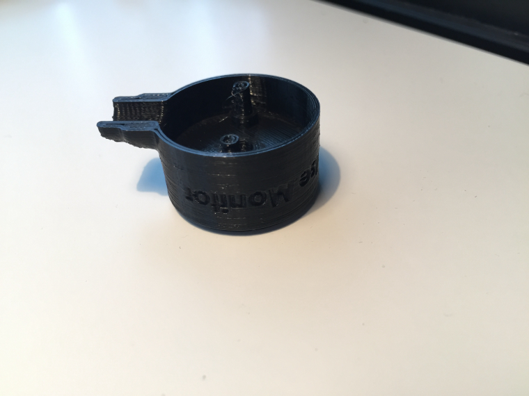
This is the bottom @scalz, the previous post was of the top part.
Yes, having the diode resessed was big importance in my eyes. Where do you live as if its not that bad we could print some for you and send to you if you wanted it after it was finished.
I have a few little tweeks to do but i'm pretty pleased with how the details have turned out.
Things to ammend:
- Change cable specs if i decide on using 4 core into a rj11 connector.
- Sort out screw holes as they need some more plastic inside to be more substantial to receive my self-tapping screws.
- Make walls slightly thicker to allow for another skin.
-
@gohan - I'm thinking either a 4p4c variant or some other board connector. If you could choose any board connector for this use then what would you prefer? Molex JST, dupont, RJ45/RJ11, 3.5mm headphone, 2.5mm headphone, USB mini/micro, anything. What would your preference be? I was only thinking RJ because it locks into place and is hard to pull out if knocked or anything.
-
@Samuel235 yep screw holes are a bit tight but it looks good ;) I did a mini tunnel too on mine for isolating a bit the sensor, i think this can help, but not sure as it also increases the distance between the blinking led, but should work.
For the connector on my side i don't really care :) or rj11/45 maybe.. -
@gohan - I'm thinking either a 4p4c variant or some other board connector. If you could choose any board connector for this use then what would you prefer? Molex JST, dupont, RJ45/RJ11, 3.5mm headphone, 2.5mm headphone, USB mini/micro, anything. What would your preference be? I was only thinking RJ because it locks into place and is hard to pull out if knocked or anything.
@Samuel235
IMHO rj11 is good because as you said it locks in place, it is not easily mistaken for whatever use, you can make a cable with rj11 plug very quickly (if you have the tool ofc). On the other hand I don't know how hard it would be to make the female socket fit in the 3D printed housing or in any sensor box where the arduino will be placed. -
As i would be making the arduino side as a custom board, then i will be able to just put a footprint onto the PCB, not an issue in that respect :)
