Current Sensing?
-
i know for the extruded text, me too though. but i think it's more in general, 3d printing, it is more readable. but you can try, sure it won't take so much time and maybe that'll work, can't wait to see how it looks now ;)
-
i know for the extruded text, me too though. but i think it's more in general, 3d printing, it is more readable. but you can try, sure it won't take so much time and maybe that'll work, can't wait to see how it looks now ;)
-
These look great, I have been working on something similar, for now just using an LM393 module with a phototransistor (or it could be a photodiode, I'm not sure). Initial experiments with a light dependent resistor LM393 module were not successful, its ramp up time was too long for what turned out to be the 15ms pulse time on my electricity meter (3200 pulses per kWh).
At present I am just using Blu-Tack to provide light isolation (my meter is mounted outside on the front porch) but I was looking at a similar enclosure. I have ordered some Velcro dots off eBay for mounting and have been looking at some enclosures but the ones I see here look much better than anything I have found so far.
@Samuel235 with your design I was thinking it might make more sense mechanically if the wire is hanging down to have it exiting the enclosure as close as possible to the plane of the mounting point so that as much of the force it is exerting is as a shear which Velcro is good at holding.
I have also ordered some other parts to try replacing the LDR on my original LM393 module, based on a combination of local availability, price, and wavelength and angular sensitivity. The two I choose are the SFH213 photodiode (wide wavelength, 10º angular) and the SFH309 phototransistor (full spectrum, 24º angular). I'm just getting back into electronics after many years so I still have to pull out the soldering iron and get a workbench set up to try these out.
@mwalker - My design has the cable coming out where it does because that is where the PCB plane is. Mine is relatively thicker than @scalz's, not 100% sure the technical details of his but my detector is not right on the surface, it has a cavity to make it nice and dark for that sensor.
My design implements a LM393 and a photodiode, which i'm sure you already know, is designed for high speed detections and fast saturation of the diode and fast release back to normal. However, my meter is not one that blinks fast (i think) and i don't have a signal generator at the moment so i wouldn't be able to test down to that speed. The photodiode has an effective window shown below:
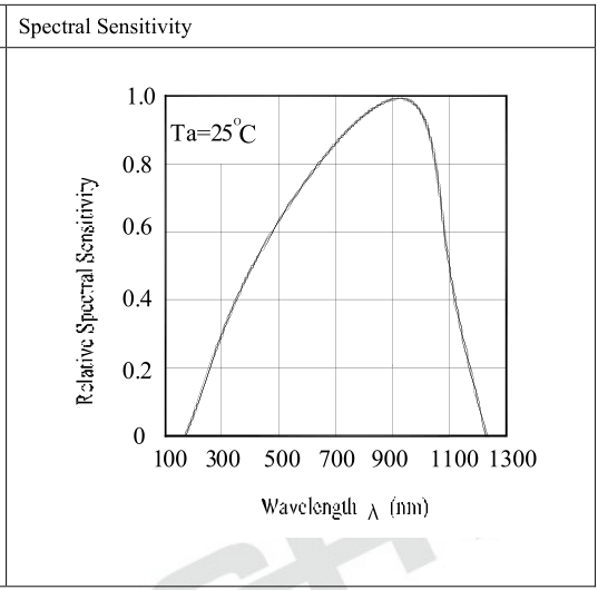
So, i think that my design may suit your use, lets see :)
-
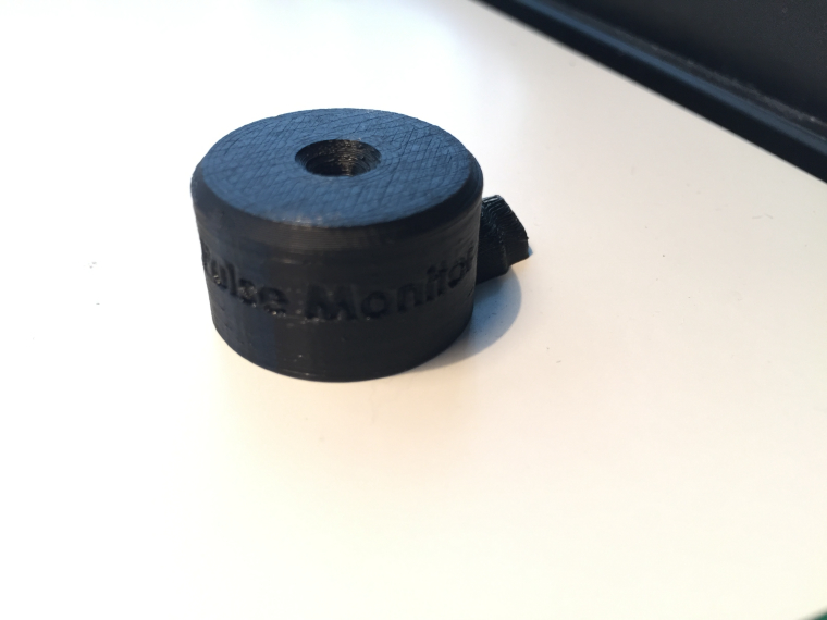
I'm pretty impressed with how it handeling that overhang on the logo considering there wasn't much vertical space under it to the bed i expected it to droop down to the bed. I like it! Ignore the little cunk out at the cable entry part, my glue held it too hard on the bed. The cable grip is a little too small, reprinting it with a more pronounced grip now (Didn't want it too large as it would damage the cable, but its not enough at the moment).
-
it didn't slice the text??
-
It looks good @Samuel235, having the detector recessed in a cavity in order to reduce the impact of ambient light isn't something that I had considered, I guess because I was mainly thinking about an off the shelf enclosure, or repurposing some other type of container, i.e. this, but I like these designs a lot better.
I was able to use a cheap logic analyser with sigrok to work out the pulse time on my meter, and I am in the midst of designing a test rig using WS2812 led strip and a separate microcontroller in order to be able to test my pulse detection code when more of the LM393 modules arrive. One location I need to use this system has ten meters, and another has nine meters, so I need to have a good test rig to make sure that my system won't be dropping pulses.
-
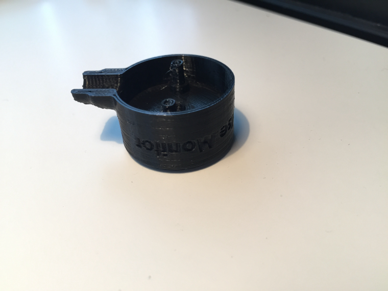
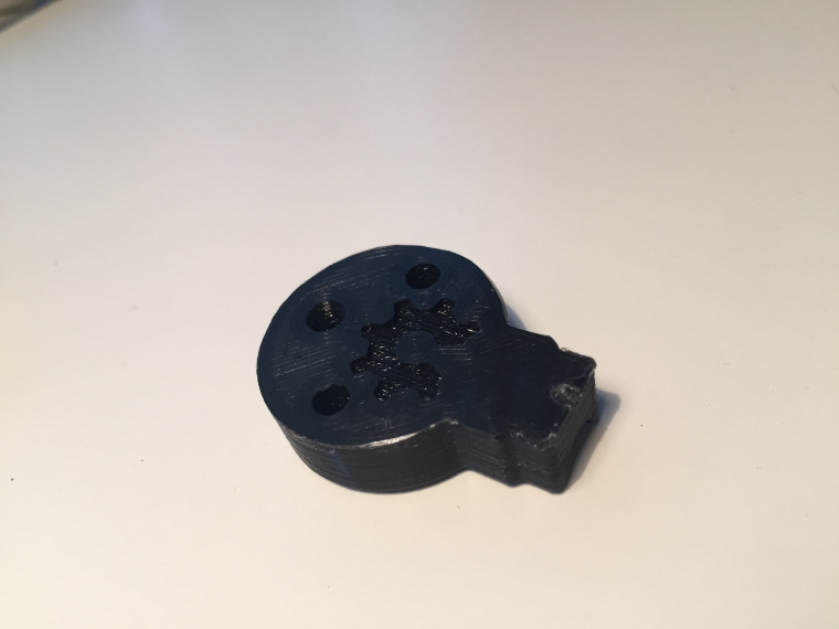
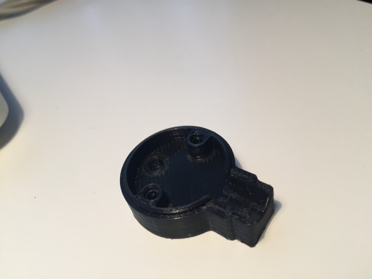
This is the bottom @scalz, the previous post was of the top part.
Yes, having the diode resessed was big importance in my eyes. Where do you live as if its not that bad we could print some for you and send to you if you wanted it after it was finished.
I have a few little tweeks to do but i'm pretty pleased with how the details have turned out.
Things to ammend:
- Change cable specs if i decide on using 4 core into a rj11 connector.
- Sort out screw holes as they need some more plastic inside to be more substantial to receive my self-tapping screws.
- Make walls slightly thicker to allow for another skin.
-
@gohan - I'm thinking either a 4p4c variant or some other board connector. If you could choose any board connector for this use then what would you prefer? Molex JST, dupont, RJ45/RJ11, 3.5mm headphone, 2.5mm headphone, USB mini/micro, anything. What would your preference be? I was only thinking RJ because it locks into place and is hard to pull out if knocked or anything.
-
@Samuel235 yep screw holes are a bit tight but it looks good ;) I did a mini tunnel too on mine for isolating a bit the sensor, i think this can help, but not sure as it also increases the distance between the blinking led, but should work.
For the connector on my side i don't really care :) or rj11/45 maybe.. -
@gohan - I'm thinking either a 4p4c variant or some other board connector. If you could choose any board connector for this use then what would you prefer? Molex JST, dupont, RJ45/RJ11, 3.5mm headphone, 2.5mm headphone, USB mini/micro, anything. What would your preference be? I was only thinking RJ because it locks into place and is hard to pull out if knocked or anything.
@Samuel235
IMHO rj11 is good because as you said it locks in place, it is not easily mistaken for whatever use, you can make a cable with rj11 plug very quickly (if you have the tool ofc). On the other hand I don't know how hard it would be to make the female socket fit in the 3D printed housing or in any sensor box where the arduino will be placed. -
As i would be making the arduino side as a custom board, then i will be able to just put a footprint onto the PCB, not an issue in that respect :)
-
@Samuel235 I'm a fair way away from anywhere in Australia, so it may not be worth it, but thank you.
For connectors I have been leaning towards them being captive on the sensor end, I was looking at RJ45 for the other end, if only because I thought I could repurpose the connector bank and case from a cheap or surplus hub/switch/router.
@mwalker - Ahh okay, no worries.
Thats makes sense for a one off for yourself, if it is just a one off then i would just wait for us to finished the pcb design and get them made up then you could just cut the connector off the end and add dupont connectors or something and push onto arduino. Unless you're waiting for the finished product with the custom arduino board too.
-
Yes, I imagine a requirement to monitor 9 or 10 separate meters at a single location is a bit of a one off, but I'll be definitely interested in what you come up with to see if I can utilise it. I expect I will be using an ESP8266 based board for the micro controller part as power supply is not an issue, and I have wifi available.
While researching bits and pieces across the internet I came across:
https://openenergymonitor.org/forum-archive/node/10707.html
which I thought may be of interest. It seems they are flashing the LED from a microcontroller output, which is an interesting way of proving that the overall system is working.
@mwalker - Okay, well at that quantity you may find it useful to get some PCBs ordered that i design and then put it in a enclosure that you can come up with (saving shipping costs from me to you). Unless you just directly copy my circuitry to your own solution, up to you! So yeah, if you wanted to use my circuitry you would just wire the three wires into the arduino rather than using a RJ11 connector, would be easier than making a enclosure with panel mounted jacks and stuff. Its much easier for me to use RJ11 connectors as i'm making the arduino side as a custom board too.
That is what i would call a backward solution. I do agree that it would allow you to see that the arduino is running, but its just not really the way i'm doing this. The LED that i will be blinking on the front of the module is being triggered by the Photodiode and comparator itself, nothing to do with the arduino (this way if someone needed to come to your meter, they can see the LED even if the arduino has failed, as long as its still getting its power. This is not really a design feature though, just a bi-product of how i've made it).
-
@Samuel235 sounds good.
More digging identified the openenergymonitor sensor is a rebadged unit manufactured in China:
The link doesn't work but it is in the Internet archive, they have a (fuzzy) photo of the internals at right at the bottom:
http://web.archive.org/web/20160819224835/https://openenergymonitor.org/emon/opticalpulsesensor
@mwalker - Same image as i found on one of the links above. They are not choosing to go the comparator method either. I will be interested to see how fast mine could detect pulses. I might take one into University/school and get the pulse/wave generator on it.