Outdoors Touch Switch light controller
-
I have a few lights around the yard under MySensors control now so I am building a touch controller to turn them on and off. This will be located at the beginning of the main path that leads to our garden areas.
The unit will be constructed using 100mm pvc pipe and connectors. There will be 4 touch studs, these will be stainless M8 cup head bolts.
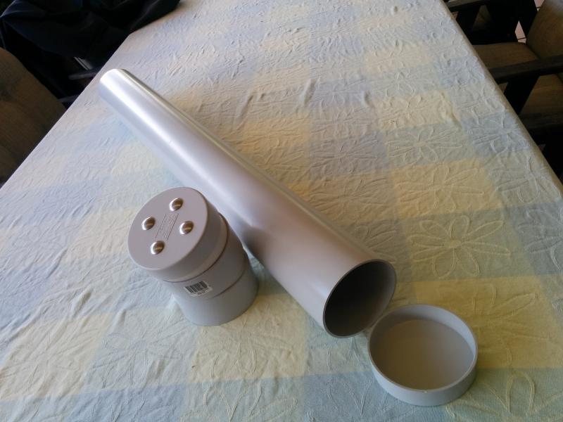
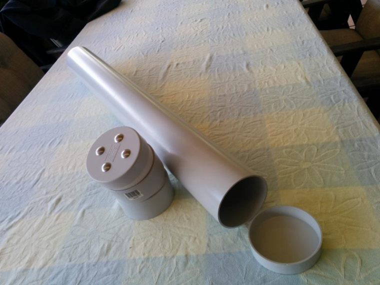
Here are the main parts to the housing. The end cap will be glued on the pipe and then partly buried. Once in the ground i will fill it with 20mm gravel to keep it stable. The touch studs and node electronics will all be located in the top joiner and cap.
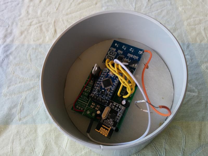
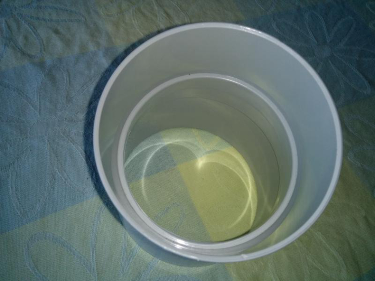
The joiner has a lip around the inside, i have used that to hold the arduino etc.
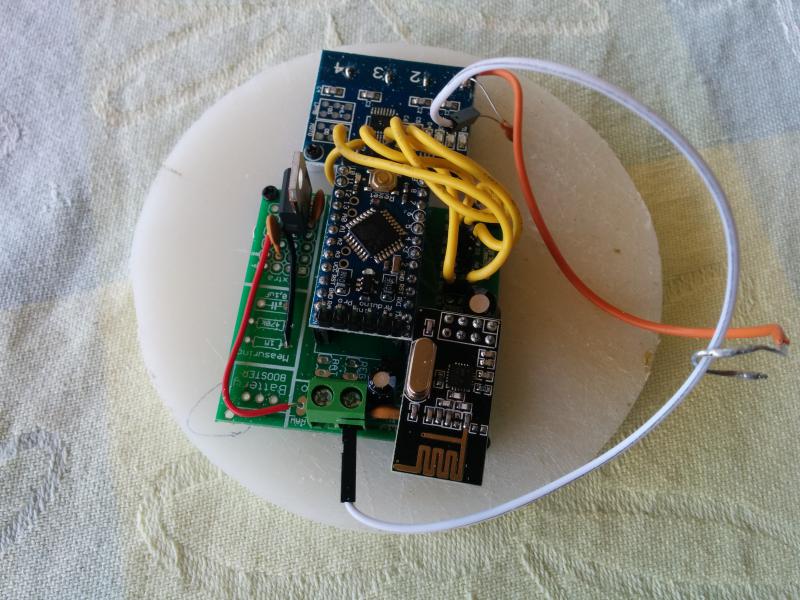
The mounting plate is made from an old plastic cutting board
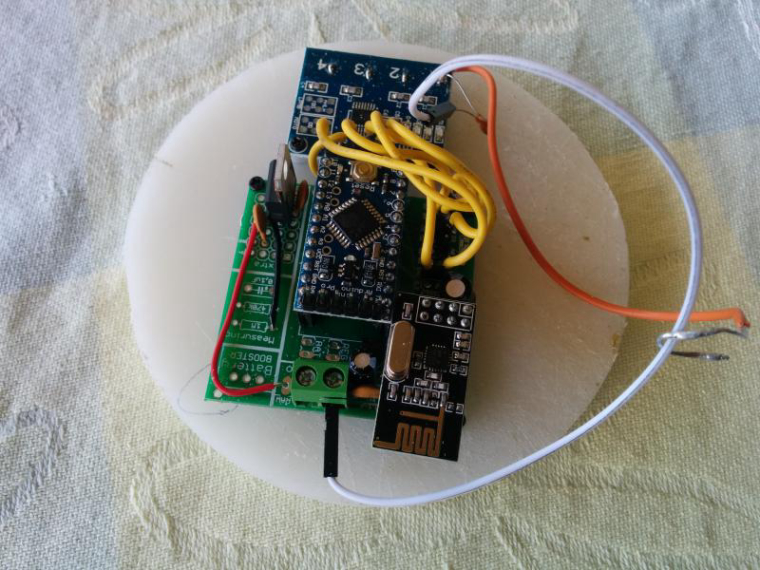
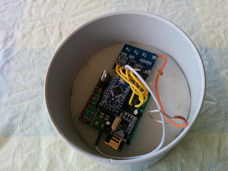
It just slips into place and uses gravity to hold it there.
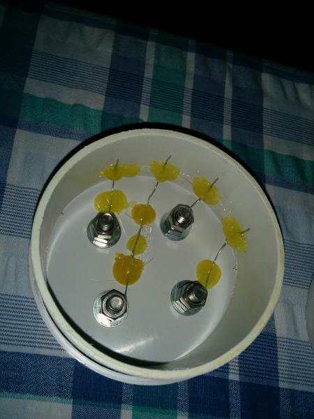
The cap with the studs uses solid wire held in place with hot glue to run out to the touch switch wires . Single dupont connectors push directly on to these. It is important to keep the wires separate from each other to reduce the chance of cross triggering.
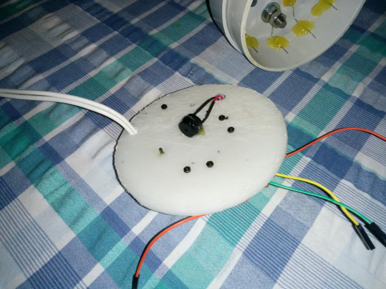
I have also added a small piezo buzzer to give an audible beep when a stud is touched.
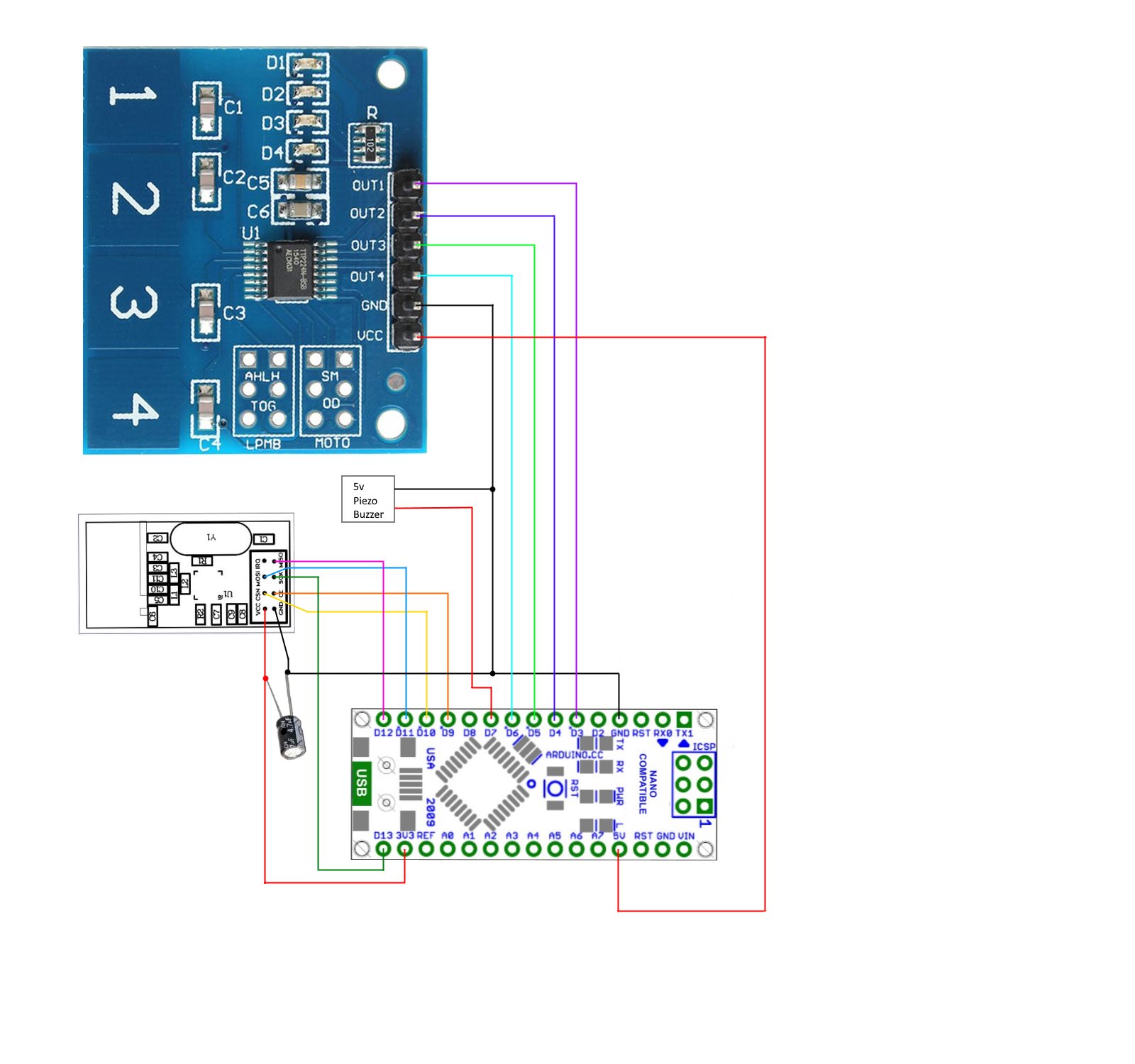
The circuit diagram. This shows it with a nano but I have used a pro mini in the actual unit.

The Sketch for the touch controller is below. It is working ok on the bench. As you can see three of the the buttons all switch the same node at the moment. I will change these to the correct id's once it is installed outside.
/*
 * This is a  MySensors node used to control
 * other Binary Switch nodes on the network.
 * It uses node to node messaging to control three nodes directly and a
 * binary switch sensor to be used as a group control in Domoticz
 * 4 way touch switch module for input.
*/

// Enable debug prints to serial monitor
#define MY_DEBUG
//#define MY_PARENT_NODE_ID 1
//#define MY_PARENT_NODE_IS_STATIC
#define MY_NODE_ID 100
#define GROUP_SW_ID 4

// Enable and select radio type attached
#define MY_RADIO_NRF24
#define MY_RF24_CHANNEL 84
#define MY_TRANSPORT_WAIT_READY_MS 3000
//#include <SPI.h>
#include <MySensors.h>

uint8_t sensorId = 3;               // Id number of the sensor to send to
uint8_t nodeId = 201;                 //Id number of the node to send to
uint8_t sendingSensorId = 1;        // Id number of the sensor sending the message

int buzzerPin = 7;          // arduino pin buzzer is connected to
int touchState[5] ;
int oldTouchState[5] ;
bool groupState = false;

MyMessage msg(GROUP_SW_ID, V_STATUS);

void setup()
{
 for(int i = 3; i < 7; i++){    //set Arduino digital pins 3 to 6 as inputs
   pinMode(i, INPUT);
 }
}

void presentation()  {
  // Send the sketch version information to the gateway and Controller
  sendSketchInfo("Touch controller", "1.0");
  // Register all sensors to gateway (they will be created as child devices)
  present(GROUP_SW_ID, S_BINARY, "Group controller switch");

}

void loop()
{
for ( int pinNo = 3, touchNo = 1; pinNo < 7; pinNo++, touchNo++){
    touchState[touchNo] = digitalRead(pinNo);                                                             // Get the current touch switch state
    if (touchState[touchNo] != oldTouchState[touchNo] && touchState[touchNo] == 1) {                      // check for new touch button push
      switch(touchNo){
       case 1:
         /*   Node to Node message format. Note: message is still routed through the gateway or repeater node,         *
          *                                      not diectly to destination Node.                                      *
          *                                                                                                            *
          *            : Id of sending  : message  :   Destination     :     Destination      : Payload                *
          *            :    sensor      :  Type    :    sensor Id      :       Node Id        :                        */
         send(MyMessage(sendingSensorId, V_STATUS).setSensor(sensorId).setDestination(nodeId).set(true));  //send message to desitination node from touch 1
         wait(5);
         tone(buzzerPin, 1200, 60);                                                                        //Play short beep to acknowledge touch.  PIN, TONE FREQUENCY, DURATION
         break;
       case 2:
         send(MyMessage(sendingSensorId, V_STATUS).setSensor(sensorId).setDestination(nodeId).set(true));  //send message to desitination node from touch 2
         tone(buzzerPin, 1200, 60);                                                                        //Play short beep to acknowledge touch
         break;
         case 3:
         send(MyMessage(sendingSensorId, V_STATUS).setSensor(sensorId).setDestination(nodeId).set(true));  //send message to desitination node from touch 3
         tone(buzzerPin, 1200, 60);                                                                        //Play short beep to acknowledge touch
         break;
       case 4:
         groupState = !groupState ;                                                                          //Toggle the state
         send(msg.set(groupState), false);                                                                   // send new state to controller, no ack requested
         tone(buzzerPin, 1200, 60);                                                                          //Play short beep to acknowledge touch
         break;
    }
  }
 }

 for (int i = 1; i < 5; i++){
  oldTouchState[i] = touchState[i];
 }
}

void receive(const MyMessage &message) {
  if (message.type == V_STATUS && message.sensor == GROUP_SW_ID) {
    groupState = message.getBool();
  }
}
Here is the double binary switch node sketch I have been using as the test receiver.
/* This sketch is to control two outdoor lights and also
 *  allow control from a remote switch
*/

// Enable debug prints to serial monitor
#define MY_DEBUG

// Enable and select radio type attached
#define MY_RADIO_NRF24
#define MY_RF24_CHANNEL 84
//#define MY_PARENT_NODE_ID 1
//#define MY_PARENT_NODE_IS_STATIC
#define MY_NODE_ID 201


//#include "SPI.h"
#include <MySensors.h>

#define LIGHT_PIN_A  6             // Arduino Digital I/O pin connected to mosfet 1
#define LIGHT_PIN_B  7             // Arduino Digital I/O pin connected to mosfet 2
#define LIGHT_ON 1                 // Output value to write to turn on attached mosfet
#define LIGHT_OFF 0                // Output value to write to turn off attached mosfet
#define CHILD_ID_LIGHT_A 3
#define CHILD_ID_LIGHT_B 4

unsigned long heartbeatDelay = 120;     // how often the heartbeat will be sent, in minutes
unsigned long lastHeartbeat = millis(); // holder for last time heartbeat was sent
bool stateA = 0;                        // State holder for light A
bool stateB = 0;                        // State holder for light B

MyMessage msgA(CHILD_ID_LIGHT_A, V_STATUS);
MyMessage msgB(CHILD_ID_LIGHT_B, V_STATUS);

void setup() {
  pinMode(LIGHT_PIN_A, OUTPUT);            //set light pin as output
  pinMode(LIGHT_PIN_B, OUTPUT);            //set light pin as output
  digitalWrite(LIGHT_PIN_A, LIGHT_OFF);    //   make sure light is off at startup
  digitalWrite(LIGHT_PIN_B, LIGHT_OFF);    //   make sure light is off at startup
}

void presentation()  {
  // Send the sketch version information to the gateway and Controller
  sendSketchInfo("Light controller", "1.0");
  // Register all sensors to gateway (they will be created as child devices)
  present(CHILD_ID_LIGHT_A, S_BINARY, "Lamp Post Light");
  present(CHILD_ID_LIGHT_B, S_BINARY, "Garden Lights");
}

void loop()
{
 heartbeatCheck();                  // call heartbeat function
}


/*-------------------------start of functions-------------------*/

void heartbeatCheck(){
 if ((millis() - lastHeartbeat) > (heartbeatDelay*60000)) {
  sendHeartbeat();
  lastHeartbeat = millis();
  #ifdef MY_DEBUG
    Serial.println("Heartbeat Sent" );
  #endif
 }
}

void receive(const MyMessage &message) {

if (message.type == V_STATUS) {                                  // check that message is for binary switch
  if (message.sender == 0) {                                     // check if message is from gateway (node 0)
    switch (message.sensor) {
     case 3:                                                     //incoming message is for light A  (sensor 3)
       stateA = message.getBool();
       digitalWrite(LIGHT_PIN_A, stateA ? LIGHT_ON : LIGHT_OFF); // Set Light A to the new state
       break;
     case 4:                                                     //incoming message is for light B  (sensor 4)
       stateB = message.getBool();
       digitalWrite(LIGHT_PIN_B, stateB ? LIGHT_ON : LIGHT_OFF); // Set Light B to the new state
       break;
   }
  }
  else  {                                                         // message is not from gateway so must be from a remote
    switch (message.sensor) {
      case 3:                                                     //incoming message is for light A (sensor 3)
        stateA = !stateA;                                         // toggle light state
        digitalWrite(LIGHT_PIN_A, stateA ? LIGHT_ON : LIGHT_OFF); // Set Light A to the new state
        send(msgA.set(stateA), false);                            //Message the gateway so controller will be aware of the change. No ack
        break;
      case 4:                                                     //incoming message is for light B  (sensor 4)
        stateB = !stateB;                                         // toggle light state
        digitalWrite(LIGHT_PIN_B, stateB ? LIGHT_ON : LIGHT_OFF); // Set Light B to the new state
        send(msgB.set(stateB ? true : false));                    //Message the gateway so controller will be aware of the change. No ack
        break;
    }
   }
  }
    /*-------Write some debug info-----*/
#ifdef MY_DEBUG
    Serial.print("Incoming change for sensor:");
    Serial.print(message.sensor);
    Serial.print(" from node: ");
    Serial.println(message.sender);
#endif
}


