MySensors weather station
-
thanks for this
one of my cups on my anemometer is broken might be able to tweak that file instead of starting from scratch now -
thanks for this
one of my cups on my anemometer is broken might be able to tweak that file instead of starting from scratch now@MasterCATZ the anemometer that I used was one that I found on thingiverse. The link is in the beginning of the thread, but I am sure you found that already. You may want to just create a whole new cup rotor for yours.
-
So, I had put this project on hold for a bit, but I am back at it. One of the parts of the project that I will be talking about in this post is the rain gauge portion of this. I had started a thread on this part a while back, but decided that I would combine everything for the weather station in this thread.
So one of the things with this rain gauge was that I wanted to make it fairly accurate. In my "tipping bucket rain gauge" thread, @BulldogLowell had mentioned that an 8 inch opening on the funnel is typical for what is used commercially, so I went with that and designed this:
Before I could print this on the 3D printer, I needed to print some different parts for my printer to allow for it to print the large size of the funnel. I also did some research on what type of plastic I should use before printing this monstrous part. Something I should have looked into more before printing the wind direction vane and wind speed rotor. Being that this will be outdoors in the sun it will need to have some UV resistance. I ended up settling on e-sun PETG filament. According to this review that I read, there was this statement that sold me on it:"It can also maintain the finished product's toughness and prevent it from turning into a yellowish color. PETG also contains UV absorber and can serve as a protective layer from the influence of ultraviolet light."
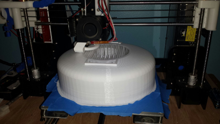
At any rate, I just got my brand new roll of white and started the print:
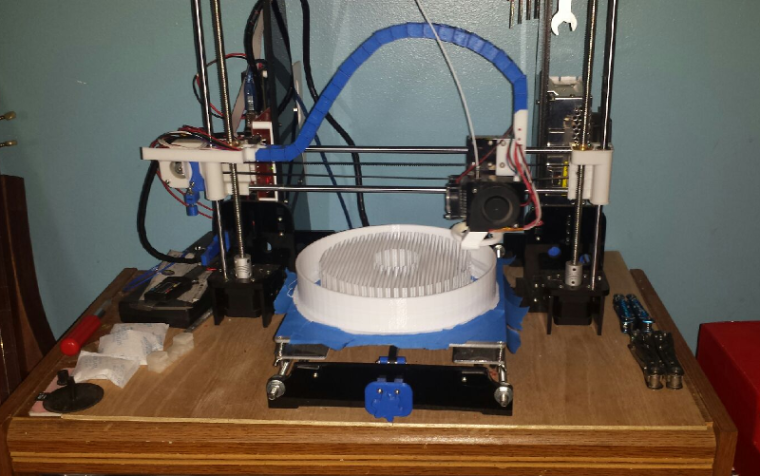
I am running at a 0.24 layer height which should be fine for this. I am printing at 30 mm/s. Cura says 44 hours 40 minutes for the print, but the times from cura are usually a bit short. I am betting on about 48 hours total print time. This will be the largest print job I have ever had the printer do. The picture is at about 17 to 18 hours into the print.Tonight I will be tweaking the design of the base that will hold the tipping bucket and sensor. I did some test prints a while back of the basic parts of this to see how they would function, and I think they worked well. This is the basic design that I have as of now:
A few tweaks to this and it should be good. The main thing is going to be figuring out how I want this to mount/attach to the rest of the system with the wind sensors and the arduino. Since this will just have the reed sensor, I will need to account for how it will get wired to the arduino. I am open for any suggestions on how to attach this to the rest of the sensors. My plan was to have some PVC pipes as the supports and mount things to that. I will need to watch out for the drain holes when mounting.All in all I think the project is coming along despite having to put it on hold for a while. As always, I am open to any feedback or suggestions that anyone can give.
Thanks for reading.
-
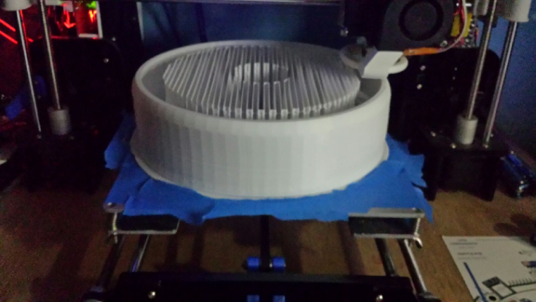
@gohan I agree, but I wanted to play it safe for when it got to the main funnel part. I opted to set the structure type to lines instead of a grid to at least keep the waste down some.
Just over 24 hours into the print. As you can see in this updated pic, it is just starting to get to what will be the top part of the funnel where it is tapering in.
-
Hello,
I found this in the forum. Perhaps it helps for the wind direction detection.
https://forum.mysensors.org/post/17825
Especially here
http://www.philpot.me/weatherinsider.html -
Hello,
I found this in the forum. Perhaps it helps for the wind direction detection.
https://forum.mysensors.org/post/17825
Especially here
http://www.philpot.me/weatherinsider.html@marco4711 Thanks for the links. I still have a few more things that I want to try to get my setup working If it comes down to it, I may use MasterCATZ' idea of using a magnetic rotational sensor. I don't give up easily.
-
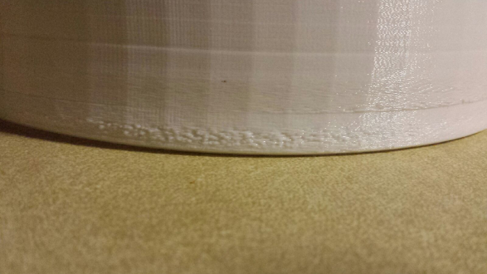
Well, the part finally finished. Roughly 46 hours. Overall, I think it will work good. It was a bit of a job clearing out all of the support material though.
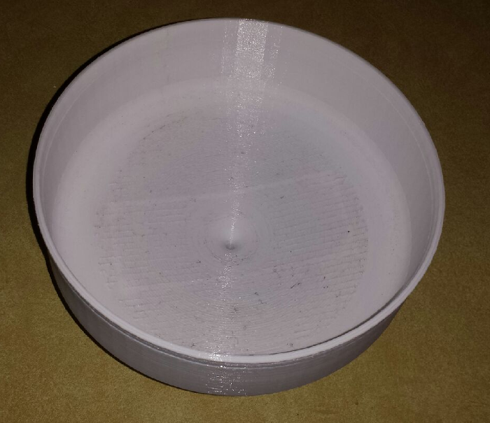
The bottom turned out well.
The first few layers had some issues, but really nothing that will defeat it's purpose. Had me worried for a short time though, but I gave it the benefit of the doubt.
-
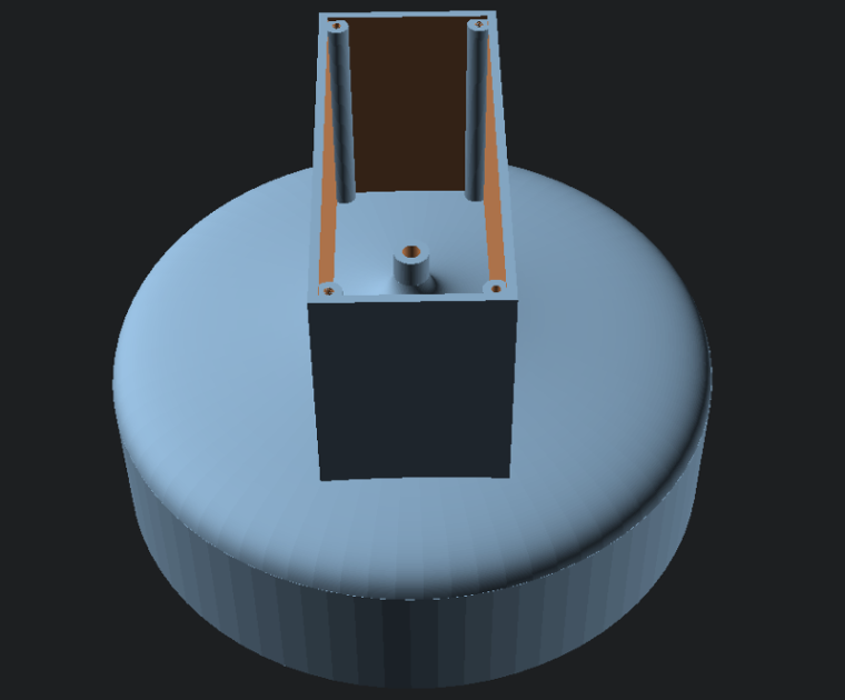
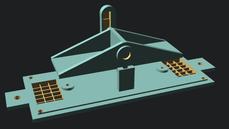
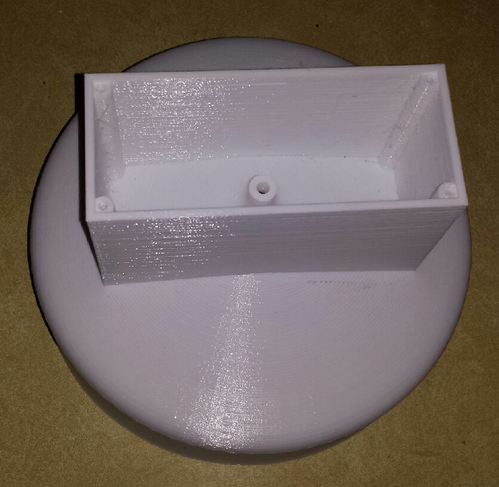
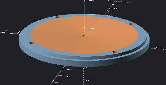
So, for the latest addition to my weather station, I decided to make a radiation shield to house a DHT22 temp and humidity sensor. I figured that I would also need a place to put the arduino to be used as a connection hub for everything and I figured this would be as good a place as any. This is my design for it:
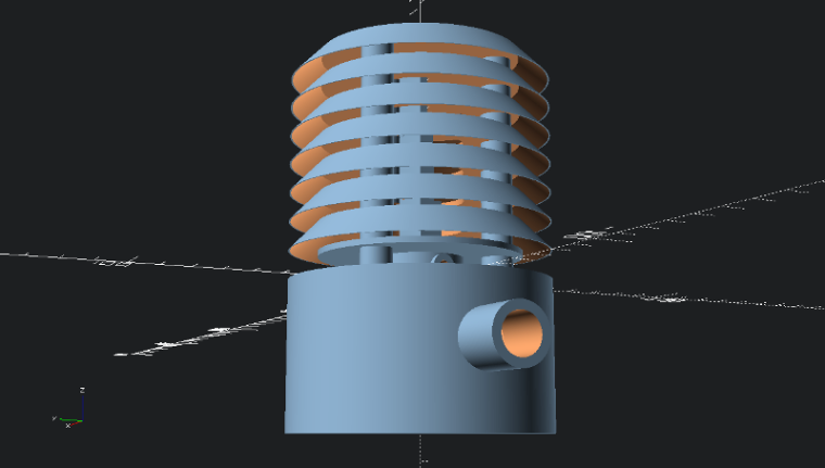
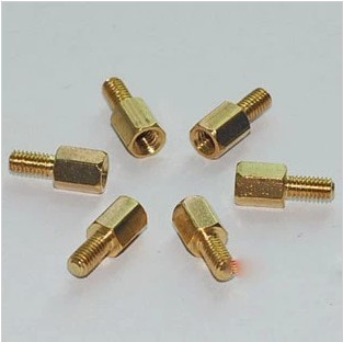
The under side of the base is where the electronics will be mounted. I have designed the standoffs to mount an easy newbie board. and should have plenty of room for wire connections as these will be fairly basic.
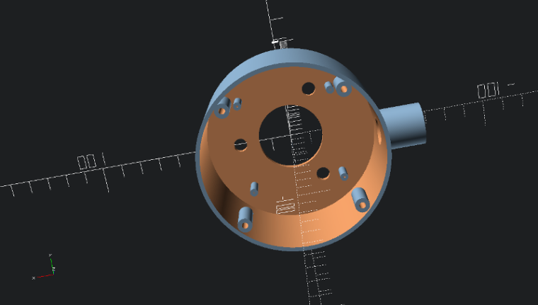
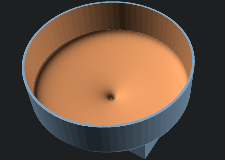
In the event that water should get inside of the unit due to wind or other factors, I have designed the bottom cover with a tapered center going to a drain hole.
I have the radiation shield and rain gauge partially assembled for now for programming and testing. I will get some better pictures of that tomorrow and post them to the thread.
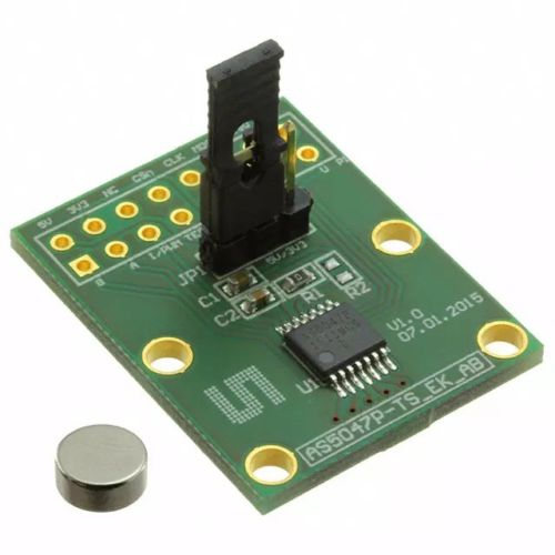
One other change that I decided on was for the wind direction sensor. Since I had a bit of trouble with the other designs that I tested using reed switches and IR phototransistors, I decided to try an AS5047P magnetic direction sensor. I ordered this one off of ebay. It was a bit expensive at $16 US plus $3.39 for shipping, but the person selling it mentioned that it comes with an extra chip. These sell on Digikey for $17 plus $7 and change for shipping, and the chips alone sell for around $9, so I didn't think it was that bad of a deal. I should have that later this week.
Once I get this assembled I think the last thing will be to figure out all of the programming, which I have a bit of a start on using the rain gauge code from the build section of the site. I have been researching the code for the anemometer, and that may take a bit of planning with everything else that I have running, but I think it can be done. With the new direction sensor module, that should be pretty straight forward as far as connection and code, I just need to decide if I want to connect it with SPI or straight analog. I am thinking though that this project is nearing completion. It was a bit of a learning curve building all of the parts, but I think it was a good journey.
As mentioned, I'll post more pics tomorrow.
-
looking good
I need to beef up my solar panels
I get 1 week before the low battery indicator switches on and I loose half my distance
instead of using 2x AA 1.5v batteries ( or 1.2v rechargeables )
I am just going to run 18650 cells and use a 4v solar panel
-
looking good
I need to beef up my solar panels
I get 1 week before the low battery indicator switches on and I loose half my distance
instead of using 2x AA 1.5v batteries ( or 1.2v rechargeables )
I am just going to run 18650 cells and use a 4v solar panel
@MasterCATZ I had actually thought of getting a small 6 volt SLA or AGM battery and connecting a small solar panel to it. I can knock out an easy battery box with a solar panel mount on my 3D printer. These are the solar panels I was looking at as possibilities:
https://www.amazon.com/Sunnytech-333ma-Module-System-Charger/dp/B00HQXQOIQ/ref=sr_1_28?ie=UTF8&qid=1499001654&sr=8-28&keywords=6+volt+solar+panel+charger
https://www.amazon.com/Portable-Module-System-Battery-Charger/dp/B01JLPM81I/ref=sr_1_39?ie=UTF8&qid=1499001192&sr=8-39&keywords=6+volt+solar+panel+charger
I just need enough power from the panel to power the arduino and sensors during the day plus a little extra to top off the battery. I figured if I ever decide to add more sensors to the station I'll have all the power I need to handle whatever I put on it. I have my Easy Newbie board set up with a 5V pro mini and power coming into the RAW input. I think I'll be set. -
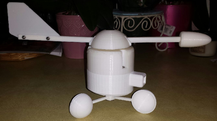
Here are a couple pics of my first prototype mounting layout of the sensors. I may still use some elbows and get the anemometer and wind direction vane moved a bit higher than the other sensors. My fear is that with all of the sensors sitting on the same plane, wind passing by the other sensor housings may affect the readings of these. The main one I am concerned with is the rain sensor. This is a minor obstacle that can be fixed with two PVC elbows.
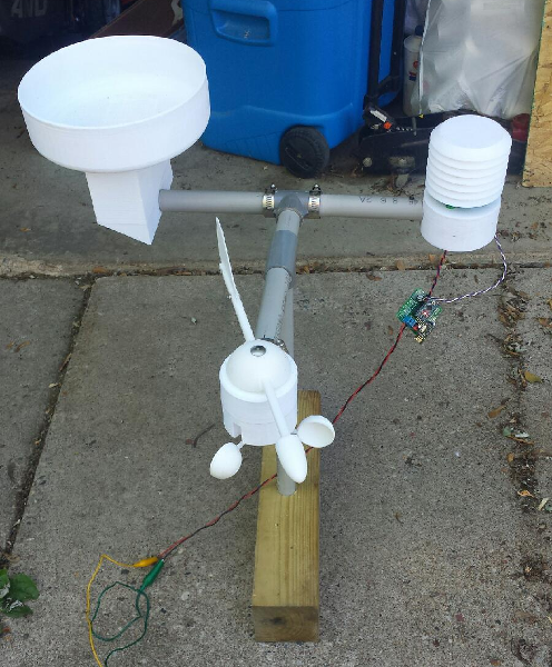
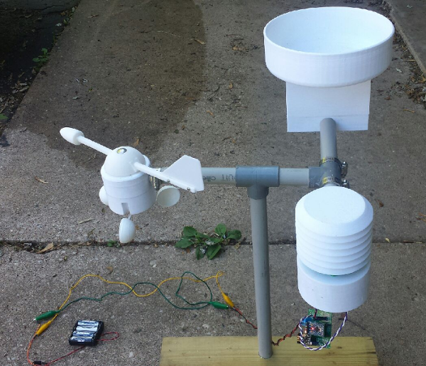
Another thing, I was thinking about the batteries that I want to use with this and I noticed that I have had the 4 - AA battery pack on for a few days now and they are still running. If I put together a pack of 2 18650 batteries, I should be good. Those batteries run at 3.7 volts, so 2 of them should give my 7.4 volts which should be no problem on the RAW input of the pro mini. My only worry with these would be overcharging them. Being that these are lithium ion batteries, they can be dangerous if overcharged. Just need to find a decent solar charging circuit for them. I am open for suggestions if anyone has any.
I hope within the next week I can have all of the OpenSCAD files cleaned up and posted on thingiverse. I wanted to post some of them a while back, but ended up making a few minor tweaks.
Enjoy...
-
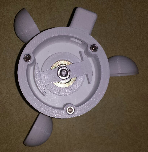
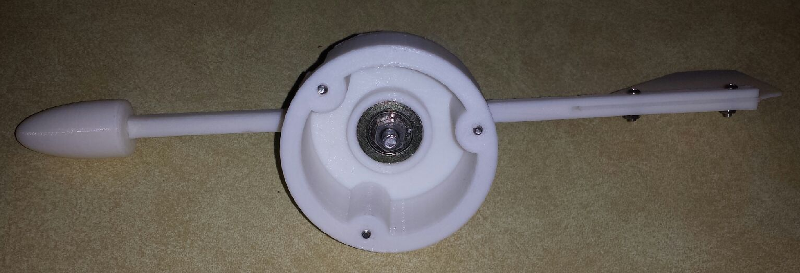
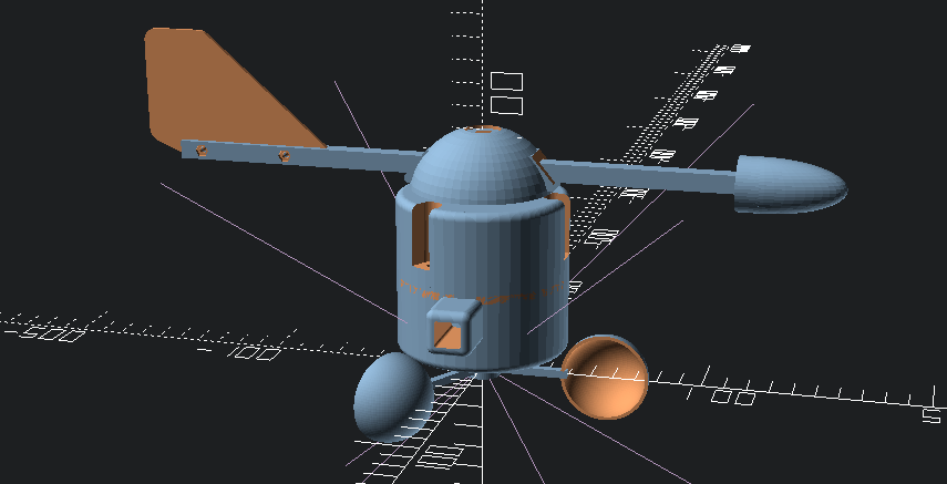
So today as I was working on the rig to change the placement of the anemometer/wind direction assembly, I ended up dropping the assembly and broke one of the cups off. As I was getting ready to make a new wind cup assembly, I decided to make a small change in the design. The change that I made has the arms holding the cups lower to better prevent wind interference from the housing. Here is the new design.
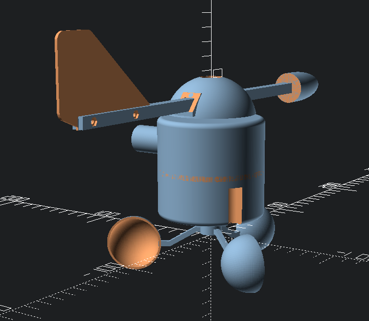
I will post more pics tomorrow of the change in placement of the anemometer assembly with the new cups.
-
You could power the pro mini directly to vcc using just one lithium cell and remove the voltage regulator and led to save power.
@gohan Right now the only Pro Minis that I have left in my parts bin are 5 volt ones. Besides, I already have the newbie board fitted with the 3.3v regulator and power caps. Another compelling reason for using a 5v mini is that it is 16MHz instead of 8MHz for the 3.3v ones. I think that I am going to want the extra speed for the number of sensors I have connected to a single pro mini and the data that I need to collect. I need to use interrupts for the pulse counting of the anemometer, so the faster I can do those things, the better off I'll be.
Vera Plus running UI7 with MySensors, Sonoffs and 1-Wire devices
Visit my website for more Bits, Bytes and Ramblings from me: http://dan.bemowski.info/ -
@gohan Right now the only Pro Minis that I have left in my parts bin are 5 volt ones. Besides, I already have the newbie board fitted with the 3.3v regulator and power caps. Another compelling reason for using a 5v mini is that it is 16MHz instead of 8MHz for the 3.3v ones. I think that I am going to want the extra speed for the number of sensors I have connected to a single pro mini and the data that I need to collect. I need to use interrupts for the pulse counting of the anemometer, so the faster I can do those things, the better off I'll be.
@dbemowsk - are your goal to sleep this sensor or whats your thoughts running it with battery? It might be a hard nut to crack 5v 16mhz and batteries?
Love your thread btw! Keep up the good work :)
Controller: Proxmox VM - Home Assistant
MySensors GW: Arduino Uno - W5100 Ethernet, Gw Shield Nrf24l01+ 2,4Ghz
MySensors GW: Arduino Uno - Gw Shield RFM69, 433mhz
RFLink GW - Arduino Mega + RFLink Shield, 433mhz -
@dbemowsk - are your goal to sleep this sensor or whats your thoughts running it with battery? It might be a hard nut to crack 5v 16mhz and batteries?
Love your thread btw! Keep up the good work :)
@sundberg84 I don't plan to sleep the sensor at all. Putting the sensor to sleep would cause problems with the anemometer and the interrupt I need to use for that. The main reason for needing it to run on battery is that I plan to mount this up in the air on the top edge of my house. This is why I want to also put a solar panel on it. During the day the solar panel can run the sensor and charge the battery, and at night the battery can take over.
-
Are you sure you don't want to sleep sensor? If it is a matter of interrupts for anemometer, you could use a dinamic sleep time, like if you don't have any wind motion within 2 seconds put the node to sleep and wake it up on pin change