Swimming Pool Thermometer
-
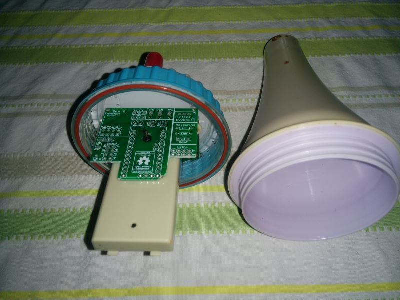
I had an old Chinese pool thermometer that used to transmit on the 433MHz band. It stopped working some time ago so we have reverted to the time honoured method of dipping ones big toe in to see if the water is ok for a swim.
Mrs boots has now clearly indicated that in the 21st century a better method was required, so without further adieu I present for your perusal the TMP36 Pool Thermometer.
I had a few TMP36 temperature sensors lying around so I have used one for this project.
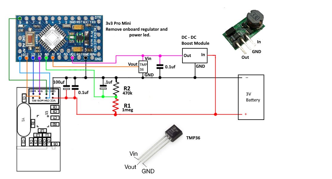
The TMP36 provides a simple analog voltage output proportional to the temperature. It has a temperature range of -40 C to 125 C with an accuracy of around 1 deg. Current draw is stated at less than 50uA and less than 0.5uA when in shutdown mode if you have a version that supports that. The 3pin TO-92 type that i had does not support shutdown mode. It requires a supply voltage of between 2.7V to 5.5V so for this node it will be connected to the DC-DC booster.
The pool thermometer has a built in battery holder for two AA batteries so the node has to run on a 3V supply.
To reduce power consumption I have removed the pro-mini power LED and onboard regulator and am using the internal 1.1V voltage reference for the analog inputs.
The TMP36 can go as high as 2v on its output pin so there is some risk that it could exceed the 1.1v limit. However it would need to be reading close to 60 C for this to occur so it is very unlikely. Anyway if my pool reaches a temp of 60 C I will probably have other things to worry about :(At this time the node has performed well on the bench with a current draw of around 65uA when asleep but It refuses to connect from the pool area, this is a bit of a black spot area at the moment so i will probably need to add a repeater to get it to connect.....finish one job and create another!
The circuit is shown below, the Arduino and the TMP36 both run off the boost module but the NRF runs directly off the battery to avoid the noise.

The sketch is pretty standard. The node spends most of its time asleep, waking every 30 min to send temp and battery level data. It will check if the temperature send was successful and resend a second time if needed before once again going to sleep.
I had a small problem with inacurate analog readings, frequently the first reading for the temp would show an unusually high result leading to a higher average overall. This aparently can happen as the arduino's adc is switched between different analog pins. The two solutions were to either to always disreguard this first reading or make an analogRead call to the pin prior to actually reading the data. I have used the second approach and it has worked./*Sketch for a low power battery operated MySensor node to monitor the temperasture of * a swimming pool. Uses a tmp36 temperature sensor connected to A1 * and a 1M , 470K voltage divider connected to A0 to monitor battery condition. * */ #define MY_DEBUG // Enable debug prints to serial monitor #define MY_RADIO_NRF24 // Enable and select radio type attached #define MY_TRANSPORT_WAIT_READY_MS 3000 //set how long to wait for connection to establish before moving on. in milliseconds //#define MY_NODE_ID 15 //#define MY_RF24_CHANNEL 84 // set channel used //#define MY_PARENT_NODE_ID 1 // set the parent node //#define MY_PARENT_NODE_IS_STATIC // force connection to parent node only. #include "MySensors.h" #define ID_S_TEMP 1 // Temp sensor ID //unsigned long sleepTime = 15000; // just used for testing unsigned long sleepTime = 60000 * 30; // Sleep time between reads (in milliseconds) (Set to 30 min at present) int tmp36Pin = A1; // analog pin tmp36 sensor is connected to int battSensePin = A0; // analog pin voltage divider is connected to float Aref = 1.0550; // temp calibration | change in small 0.000x steps to refine temp readings int sampleCount = 0; int sum = 0; int numSamples = 10; // number of samples to take int oldBatteryPcnt = 0; MyMessage msg_S_Temp(ID_S_TEMP,V_TEMP); void setup() { analogReference(INTERNAL); // use the 1.1 V internal reference wait (5000); // give node a chance to fully boot before proceeding on startup } void presentation() { sendSketchInfo("Pool Temperature Sensor", "1.0"); // Send the sketch version information to the gateway and Controller present(ID_S_TEMP, S_TEMP,"Pool Temp"); // Register Sensor to gateway } void loop() { sendTemperature(); // call function to send temperature data sendBattery(); // call function to send battery level Serial.println("------ sleeping now ----- "); sleep(sleepTime); // sleep until next scheduled check Serial.println("------awake now--------"); wait (150); // small wait to allow to stabalise after sleep. } /*-------------------start of functions--------------------------*/ void sendTemperature() { analogRead(tmp36Pin); // pre-select analog pin to stabalise first reading wait(10); sampleCount = 0; sum = 0; while (sampleCount < numSamples) { //Take multiple readings fromt the tmp36 to improve accuracy int tmp36 = analogRead(tmp36Pin); sum += tmp36; sampleCount++; Serial.print("raw ADC reading = "); Serial.println(tmp36); wait(10); } float tmp36Raw = sum / numSamples; // work out the average result Serial.print("averaged ADC reading = "); Serial.println(tmp36Raw); //float voltage = tmp36Raw * 1.1; //work out the voltage. used for debugging only // voltage /= 1024.0; // Serial.print(voltage); Serial.println(" volts"); // print out the voltage float tempC = tmp36Raw * Aref * 0.1 - 50.0; // raw data to celcius conversion for TMP36 Serial.print(tempC); Serial.println(" degrees C"); if (!send( msg_S_Temp.set(tempC,1),true)) { // try and send data to gateway and check if successful Serial.println(" No uplink sending again "); wait(150); // a small wait before trying again send( msg_S_Temp.set(tempC,1)) ; //try to resend the data one more time before sleeping. no ack needed this time. } } /*-------------------------MySensors battery check--------------------------------------------*/ // 1M, 470K divider across battery and using internal ADC ref of 1.1V // Sense point is bypassed with 0.1 uF cap to reduce noise at that point // ((1e6+470e3)/470e3)*1.1 = Vmax = 3.44 Volts // 3.44/1023 = Volts per bit = 0.003363075 void sendBattery() { analogRead(battSensePin); // pre-select analog pin to stabalise first reading wait(10); sampleCount = 0; sum = 0; while (sampleCount < numSamples) { //Take multiple readings fromt the voltage divider to improve accuracy sum += analogRead(battSensePin); sampleCount++; wait(10); } int batteryPcnt = round((sum / numSamples)/10); // work out the average result and then Percentage Serial.print(batteryPcnt);Serial.println(" percent battery available "); if (oldBatteryPcnt != batteryPcnt) { sendBatteryLevel(batteryPcnt); oldBatteryPcnt = batteryPcnt; } }These Chinese pool temperature gauges can be bought for around the $20 mark

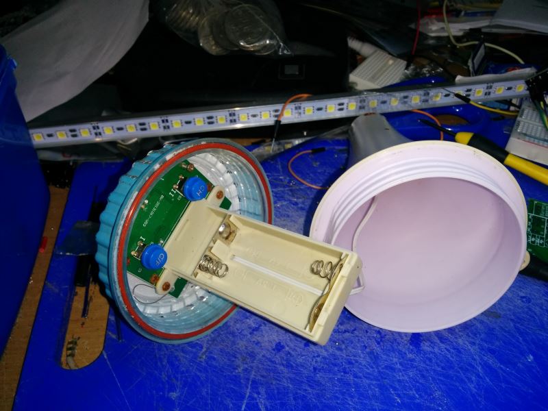
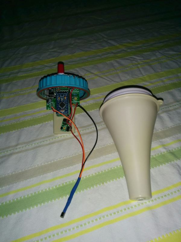
I have once again used an Easy/newbie board for this project, thank you @sundberg84 . I had to cut it down a bit to get it to fit , all I lost was the NRF connection to pin 9 so i just wired that in directly. The board is bolted to the original battery holder.
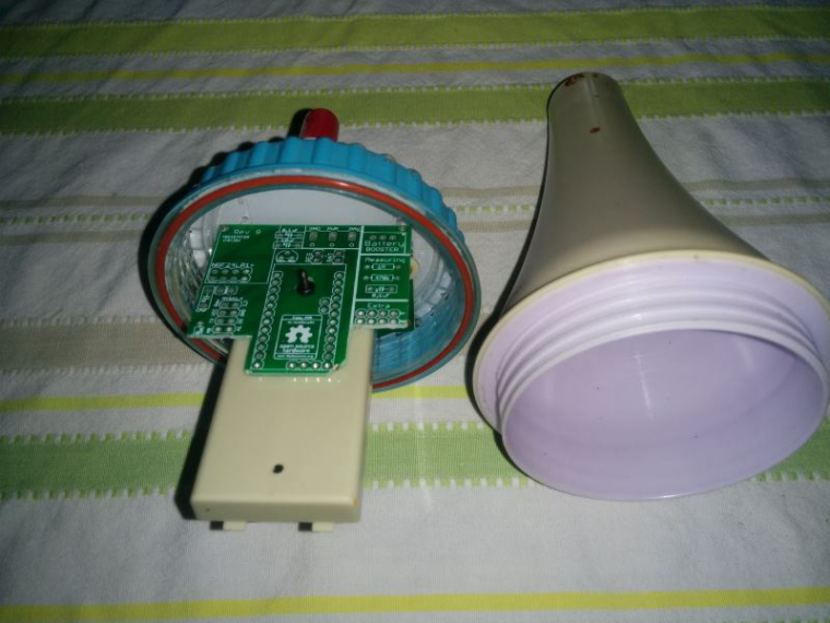
Here is the finished node ready to assemble. I had to move the DC-DC booster as it protruded too far and was scraping on the lid. The TMP36 fits down in the bottom of the case. As you can see the NRF sits up nice and high.
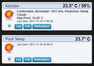
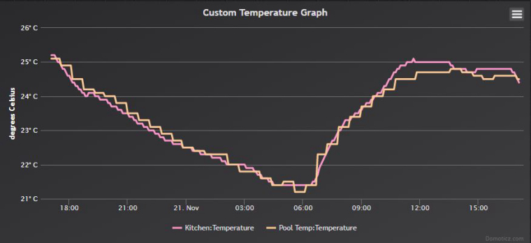
I tested it next to my kitchen temperature gauge and it proved to be pretty close.
Now I will have to get to work on a repeater so It will actually work in the pool. ;)
-
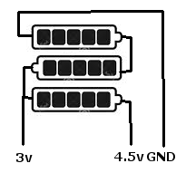
Why put the pro mini on the booster? The pro mini should run down to 1.8v, so you should be able to tap that directly off of the battery. The only thing that may require the boost voltage would be the TMP36 which has a minimum of 2.7v. I would figure the less you pull from the boost converter the better. If noise becomes an issue, you could switch your battery pack from a 2xAA pack to a 3xAA pack and do something like this and use the 4.5v for the TMP36 and/or the pro mini and everything else off of the 3v leg.
Nice project though
-
Nice project! I did one also with the same original thermometer. A couple of differences with mine:
- I used a DS18B20 which can run at a much lower voltage, so my batteries can get to about 2.0v before problems happen.
- No boost converter, everything runs straight of 2 batteries so the part count is less as well as avoiding losses in the converter.
- Battery voltage measurement is via the Vcc library which uses no external connections to the arduino, but is accurate enough for this use case.
In the past 5 months my battery voltage has stayed at around 2.97v.
@buxtronix Did you do a write up for that project, i would be keen to see your setup and sketch etc.
I had a couple of DS18B20 here also but thought they may draw a little too much, clearly they are working for you though... well done@dbemowsk thanks for your information, I was unaware the pro mini could go down to 1.8v without modifying the clock speed and fuses, I have not done any real investigation into battery powering as until recently nearly all my nodes have been powered by our house solar installation.
At the moment this temp node is functioning well (all be it not in the pool yet) so unless it is a battery chewer I am happy with it to stay as is.
It is now in a different room to the kitchen temp sensor but you can see it is still tracking quite well.
-
@Boots33 I haven't done a writeup of mine, perhaps I should fish it out of the pool sometime and get some photos.
The DS18B20 has a tiny standby current, something like 750nA. Even with 30 second poll intervals, I'm finding my sensors typically get near-shelf life from the batteries.
The physical setup is pretty basic - just a Pro Mini, battery, radio, and ds18b20. There's no circuitry for regulators, dc convertors or battery sensing. Of course I did remove the onboard regulator as it will draw power from the 'out' pin.
One thing I had to do was reprogram the fuses - you may find the Pro Mini comes with the BoD fuses set to like 2.7v. You can set it down to 1.8v so you'll get much longer life out of it. The effort is worth avoiding the hassle of more frequent battery changes.
Battery level sensing uses this VCC library: https://github.com/Yveaux/Arduino_Vcc
-
@buxtronix Did you do a write up for that project, i would be keen to see your setup and sketch etc.
I had a couple of DS18B20 here also but thought they may draw a little too much, clearly they are working for you though... well done@dbemowsk thanks for your information, I was unaware the pro mini could go down to 1.8v without modifying the clock speed and fuses, I have not done any real investigation into battery powering as until recently nearly all my nodes have been powered by our house solar installation.
At the moment this temp node is functioning well (all be it not in the pool yet) so unless it is a battery chewer I am happy with it to stay as is.
It is now in a different room to the kitchen temp sensor but you can see it is still tracking quite well.
@Boots33 - if you are using the EasyPCB this as @buxtronix mentioned are described under "Battery without step up booster (advanced users)" so you can do this with your current hardware as well.
Controller: Proxmox VM - Home Assistant
MySensors GW: Arduino Uno - W5100 Ethernet, Gw Shield Nrf24l01+ 2,4Ghz
MySensors GW: Arduino Uno - Gw Shield RFM69, 433mhz
RFLink GW - Arduino Mega + RFLink Shield, 433mhz -
@Boots33 - if you are using the EasyPCB this as @buxtronix mentioned are described under "Battery without step up booster (advanced users)" so you can do this with your current hardware as well.
Thanks @sundberg84 I will have a look and learn some more 😊
-
I now have a repeater in range of the pool area so the temperature node is finally transmitting data back to Domoticz.
Here it is lounging about the pool, it sits nice and level and is still afloat after a couple of days in the water.
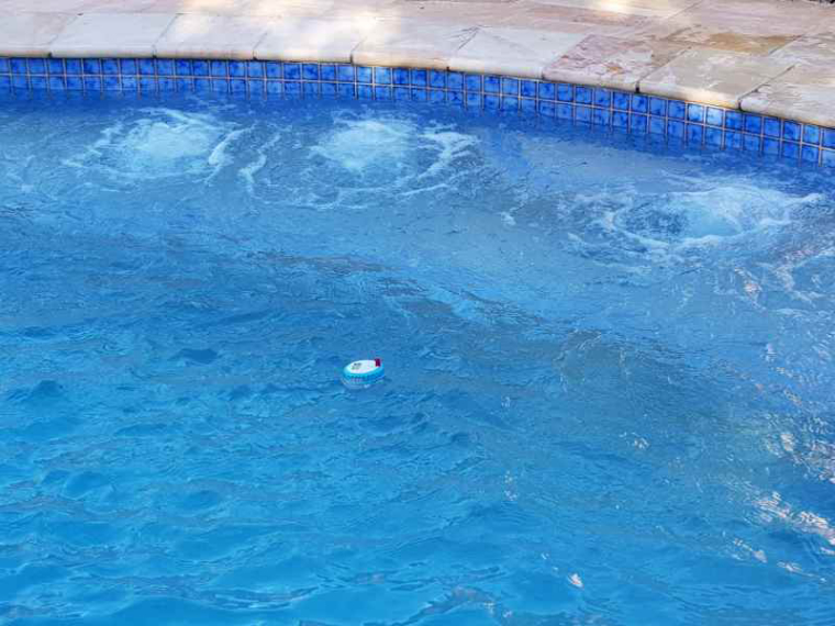
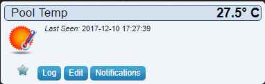
Pool temp is is nice and comfy at the moment
-
I now have a repeater in range of the pool area so the temperature node is finally transmitting data back to Domoticz.
Here it is lounging about the pool, it sits nice and level and is still afloat after a couple of days in the water.
Pool temp is is nice and comfy at the moment
@boots33 That looks refreshing. Currently the outside temp here is 21°F/-6°C with snow on the ground. The cold weather here has only been around for a short time and already I want it to go away.
Vera Plus running UI7 with MySensors, Sonoffs and 1-Wire devices
Visit my website for more Bits, Bytes and Ramblings from me: http://dan.bemowski.info/ -
@boots33 That looks refreshing. Currently the outside temp here is 21°F/-6°C with snow on the ground. The cold weather here has only been around for a short time and already I want it to go away.
Hello! It looks like you're interested in this conversation, but you don't have an account yet.
Getting fed up of having to scroll through the same posts each visit? When you register for an account, you'll always come back to exactly where you were before, and choose to be notified of new replies (either via email, or push notification). You'll also be able to save bookmarks and upvote posts to show your appreciation to other community members.
With your input, this post could be even better 💗
Register Login