Windows GUI/Controller for MySensors
-
Fortunately a helpful guy gave me your bootloader 1.3 beta, which fixes the problem with nonworking bootloader commands. It seems I was not the first one asking you...
For all others trying the bootloader commands in bootloader 1.1 : this does not work at all, and you are only wasting your time.
I would really appreciate if the code for bl 1.3 was on github also. I do not mind if its beta only...
Below the working debug output for a reassign nodeid 8 --> nodeid 88
16.01.2016 23:06:46 RX 8;255;3;0;9;0108A000B9F7FFFEDA7221F0001E950F09 16.01.2016 23:06:48 RX 0;0;3;0;9;read: 8-8-0 s=255,c=4,t=0,pt=6,l=10,sg=0:1E00010048047AA801 16.01.2016 23:06:48 INFO BL version=259 16.01.2016 23:06:48 INFO Executing bootloader command section 16.01.2016 23:06:48 TX 8;255;4;0;1;0200580000007ADA 16.01.2016 23:06:48 RX 8;255;4;0;0;1E00010048047AA80103 16.01.2016 23:06:48 RX 0;0;3;0;9;send: 0-0-8-8 s=255,c=4,t=1,pt=6,l=8,sg=0,st=ok:02005800000 16.01.2016 23:06:48 RX 0;0;3;0;9;read: 88-88-255 s=255,c=3,t=7,pt=1,l=1,sg=0:0@stebra The 1.3 is a closed beta and is not supposed to be distributed (ping @niccodemi). It is not supported in any terms nor should it be used in a productive environment, the compatibility to any library version is not guaranteed.
Currently, there is ongoing work for MYSBootloader 2.0 and the ETA is tbd, same for the code. -
A quick one: How long does the OTA takes for Blink sketch?
I press update FW, it start rolling and the node changes status from "fw updating" to "booting" but then goes back to fw updating... have been going like this for a long time now (1000 packages sent/recieved).
Also - is it possible to upload via fdti with MYSBootloader or you need to use OTA?
Edit: somethings is not right, its rebooting or starting over again:
2016-01-16 21:09:41 RX 14;255;4;0;2;0A0001002F00 2016-01-16 21:09:43 TX 14;255;4;0;3;0A0001002F008083E1EBF0E0808184608083E0EBF0E0 2016-01-16 21:09:43 RX 14;255;4;0;2;0A0001002F00 2016-01-16 21:09:45 DEBUG Undefined firmware/type for node=14 2016-01-16 21:09:45 INFO BL version=257 2016-01-16 21:09:45 INFO Send FW info to node 14: type=A, version=1, blocks=0x0048, CRC=0xD098 2016-01-16 21:09:45 TX 14;0;4;0;1;0A000100480098D0 2016-01-16 21:09:45 RX 14;255;4;0;0;FFFFFFFFFFFFFFFF0101 2016-01-16 21:09:46 DEBUG FW update started, node id = 14 2016-01-16 21:09:46 TX 14;255;4;0;3;0A0001004700E1F30E940000F9CF0895F894FFCFFFFF 2016-01-16 21:09:46 RX 14;255;4;0;2;0A0001004700 2016-01-16 21:09:47 TX 14;255;4;0;3;0A0001004700E1F30E940000F9CF0895F894FFCFFFFF 2016-01-16 21:09:47 RX 14;255;4;0;2;0A0001004700 2016-01-16 21:09:48 TX 14;255;4;0;3;0A00010046002C020E947000C0E0D0E00E948B002097 -
Hello @tekka,
is the feature 'save nodes' supposed to be working or WIP? With every start of MYSController I get a blank page and have to wait for every sensor to appear. At the moment that's not a big problem for me because of only 3 sensors, but already got a doubled ID once because new sensor requested an ID before the old #1 was recognized.
Thanks a lot for your work with the controller, it's great. -
Hi all,
I've been working on this project since some time, basically it's a GUI for controlling/updating/debugging a network of MySensors nodes. OTA functionality is supported via MYSBootloader - read posts for further instructions/troubleshooting or PM.
link updated: MYSController Version 1.0.0.3316 released
New features:
- support OTA FW update Sensebender board
- metric/imperial system I_CONFIG
- save nodes
Update via update button in MYSController or download here.
@tekka
Hi, just found this so downloaded and installed. Went to config to see what was there and selected TCP/IP tab to turn it off as it is not on a network and I only need Serial. The thing locks up and crashes and I have to use Task Manager to end it.Is there some way to start it without it trying to access 192.168.0.5?
-
Hello everyone,
I am new to the forum, I really appreciate your community.
I embarked on the adventure of MySensors and naturally, I leaned on OTA. To do so, I followed your tutorial but I have a problem when sending the FW on the node.
My setup:
• 1 Arduino Mega with nRF24L01+ which I use serial gateway
• 1 Arduino mini pro 3.3 volts for 8 mhz node (single sketch that sends a random data every 5 seconds)
• Arduino IDE 1.6.7
• MySensors libraries 1.5.3
• MYSController_0_1_2_282The mini pro flashed with the bootloader (MYSBootloader 1.1), I can detect through MYSController application where it is named "Booting: 65 ... - 65 ...", I right click on it and send the skit "blink" .
Sometimes I manage to push the "blink" directly and other times must be repeated 2-3 times (that's a lot of times, I grant you ). What is troubling is that at that time, I see the LED 13 of the mini pro flashed at a steady pace, but in MYSController, it is always named "booting ..." and to name the sketch "null".
Afterwards, when I try to put my sketch, it loads but still in a loop with an error when it reaches 100% "FW update on the failed node = 1" and then starts again at 0% and so on.
I hope you will refer me.
Thank you.
-
Hi all,
I've been working on this project since some time, basically it's a GUI for controlling/updating/debugging a network of MySensors nodes. OTA functionality is supported via MYSBootloader - read posts for further instructions/troubleshooting or PM.
link updated: MYSController Version 1.0.0.3316 released
New features:
- support OTA FW update Sensebender board
- metric/imperial system I_CONFIG
- save nodes
Update via update button in MYSController or download here.
@tekka
Using the SerialGateway:
Is there a tutorial at all for using this? I can figure out a lot of stuff, but...Is it possible to assign the ID to a new node? I want to group Nodes numerically as in Area-1: = 10,11,12 then Area-2: = 20,21,22,23 etc
How? -
Tutorial would be awesome :)
I have a specific case that fails uploading sketch to 3.3v pro mini. I have a combined sketch which works fine if uploaded to 3.3v via cable, sketch also uploads fine OTA on 5v pro mini. When I try to upload sketch to 3.3v it fails eventually. If I upload "blink" from MysController, it uploads and works fine.
I am suspecting that i am not flashing bootloader properly maybe. This is my boards.txt## Arduino Pro or Pro Mini (3V3 & 5V, 16 MHz) w/ ATmega328 MYSBootloader ## ------------------------------------------------- proMYSBL.name=ATmega328 16Mhz MYSBootloader proMYSBL.upload.tool=avrdude proMYSBL.upload.protocol=arduino proMYSBL.upload.maximum_size=30720 proMYSBL.upload.maximum_data_size=2048 proMYSBL.upload.speed=115200 proMYSBL.bootloader.tool=avrdude proMYSBL.bootloader.low_fuses=0xF7 proMYSBL.bootloader.high_fuses=0xDA proMYSBL.bootloader.extended_fuses=0x06 proMYSBL.bootloader.unlock_bits=0x3F proMYSBL.bootloader.lock_bits=0x0F proMYSBL.bootloader.file=MySensors/MYSBootloader.hex proMYSBL.build.mcu=atmega328p proMYSBL.build.f_cpu=16000000L proMYSBL.build.board=AVR_UNO proMYSBL.build.core=arduino proMYSBL.build.variant=standard ## Arduino Pro or Pro Mini (3V3 & 5V, 8 MHz) w/ ATmega328 MYSBootloader ## ------------------------------------------------- proMYSBL8.name=ATmega328 internal 8Mhz with MYSBootloader proMYSBL8.upload.tool=avrdude proMYSBL8.upload.protocol=arduino proMYSBL8.upload.maximum_size=30720 proMYSBL8.upload.maximum_data_size=2048 proMYSBL8.upload.speed=57600 proMYSBL8.bootloader.tool=avrdude proMYSBL8.bootloader.low_fuses=0xE2 proMYSBL8.bootloader.high_fuses=0xDA proMYSBL8.bootloader.extended_fuses=0x06 proMYSBL8.bootloader.unlock_bits=0x3F proMYSBL8.bootloader.lock_bits=0x3F proMYSBL8.bootloader.file=MySensors/MYSBootloader.hex proMYSBL8.build.mcu=atmega328p proMYSBL8.build.f_cpu=8000000L proMYSBL8.build.board=AVR_UNO proMYSBL8.build.core=arduino proMYSBL8.build.variant=standardI can burn 5v bootloader with both "boards" from ArduinoIDE using Uno as ISP. And on two 5v I have, OTA works great, it is just 3.3v with larger sketch (sketch is combination of several sensors) that eventually gives
14.02.2016 18.00.53	TX	1;255;4;0;3;C900FFFF72057500000101010101731B731B01000000
14.02.2016 18.00.53	RX	1;255;4;0;2;C900FFFF7205
14.02.2016 18.01.27	ERROR	FW upload failed for node=1
14.02.2016 18.01.27	INFO	BL version=257
14.02.2016 18.01.27	INFO	Send FW info to node 1: type=C9, version=FFFF, blocks=0x0580, CRC=0x6F0D
14.02.2016 18.01.27	TX	1;0;4;0;1;C900FFFF80050D6F
14.02.2016 18.01.27	RX	1;255;4;0;0;0A0001004800FFFF0101
14.02.2016 18.01.27	DEBUG	FW update started, node id = 1
14.02.2016 18.01.27	TX	1;255;4;0;3;C900FFFF7F05FFFFFFFFFFFFFFFFFFFFFFFFFFFFFFFF
14.02.2016 18.01.27	RX	1;255;4;0;2;C900FFFF7F05
14.02.2016 18.01.57	ERROR	FW upload failed for node=1
14.02.2016 18.01.57	INFO	BL version=257
14.02.2016 18.01.57	INFO	Send FW info to node 1: type=C9, version=FFFF, blocks=0x0580, CRC=0x6F0D
14.02.2016 18.01.57	TX	1;0;4;0;1;C900FFFF80050D6F
14.02.2016 18.01.57	RX	1;255;4;0;0;0A0001004800FFFF0101
14.02.2016 18.01.57	DEBUG	FW update started, node id = 1
14.02.2016 18.01.57	TX	1;255;4;0;3;C900FFFF7F05FFFFFFFFFFFFFFFFFFFFFFFFFFFFFFFF
14.02.2016 18.01.57	RX	1;255;4;0;2;C900FFFF7F05
14.02.2016 18.01.57	TX	1;255;4;0;3;C900FFFF7E05FFFFFFFFFFFFFFFFFFFFFFFFFFFFFFFF
This is the "universal" sketch I am trying to upload, it is a combination of few sensors
/**
 * The MySensors Arduino library handles the wireless radio link and protocol
 * between your home built sensors/actuators and HA controller of choice.
 * The sensors forms a self healing radio network with optional repeaters. Each
 * repeater and gateway builds a routing tables in EEPROM which keeps track of the
 * network topology allowing messages to be routed to nodes.
 *
 * Created by Henrik Ekblad <henrik.ekblad@mysensors.org>
 * Copyright (C) 2013-2015 Sensnology AB
 * Full contributor list: https://github.com/mysensors/Arduino/graphs/contributors
 *
 * Documentation: http://www.mysensors.org
 * Support Forum: http://forum.mysensors.org
 *
 * This program is free software; you can redistribute it and/or
 * modify it under the terms of the GNU General Public License
 * version 2 as published by the Free Software Foundation.
 *
 *******************************
 *
 * REVISION HISTORY
 * Version 1.0 - Henrik Ekblad
 *
 * DESCRIPTION
 * Motion Sensor example using HC-SR501
 * http://www.mysensors.org/build/motion
 *
 */

// Enable debug prints
// #define MY_DEBUG

// Enable and select radio type attached
//#define MY_RADIO_NRF24
//#define MY_RADIO_RFM69

//Hum
#include <SPI.h>
#include <MySensor.h>
//temp
#include <DHT.h>
//lux
#include <BH1750.h>
#include <Wire.h>
#include <Vcc.h>                                    // library for internal reference Vcc reading


// Reference values for ADC and Battery measurements
const float VccMin          = 1.0*2.5 ;             // Minimum expected Vcc level, in Volts. Example for 1 rechargeable lithium-ion.
const float VccMax          = 1.0*3.0 ;             // Maximum expected Vcc level, in Volts.
//const float VccMin        = 2.0*0.6 ;             // Minimum expected Vcc level, in Volts. for 2xAA Alkaline.
//const float VccMax        = 2.0*1.5 ;             // Maximum expected Vcc level, in Volts.for 2xAA Alkaline.
const float VccCorrection   = 3.30/3.42 ;           // Measured Vcc by multimeter divided by reported Vcc
Vcc vcc(VccCorrection);                             // instantiate internal voltage measurement lib


const float tempThreshold		= 0.02 ;               // send only if change > treshold (Celcius)
const float humThreshold		= 0.05 ;               // send only if change > treshold (% RG)
const float voltageThreshold	= 0.01 ;               // send only if change > treshold (Volt)
const float luxThreshold		= 1 ;               // send only if change > treshold (Lux)


const int heartbeat		= 60 ;                          // heartbeat every hour (x times SLEEP_TIME)
unsigned long lastHeartbeat = 0 ;
float lastHumidity		= 0 ;
float lastTemperature	= 0 ;
float lastVoltage		= 0 ;
boolean lastTripped		= false ;
// flags to indicate if transmission is needed, heartbeat and/or changes > treshold
boolean txHumidity		= true ;                         // flags to indicate if transmit is needed (time & change driven)
boolean txTemperature	= true ;
boolean txLux			= true ;
boolean txVoltage		= true ;
boolean txTripped		= true ;


unsigned long SLEEP_TIME = 30000; 			// Sleep time between reports (in milliseconds)
#define DIGITAL_INPUT_SENSOR		3   	// The digital input you attached your motion sensor.  (Only 2 and 3 generates interrupt!)
#define INTERRUPT DIGITAL_INPUT_SENSOR-2 	// Usually the interrupt = pin -2 (on uno/nano anyway)
#define HUMIDITY_SENSOR_DIGITAL_PIN 4      	//Humidity
#define CHILD_ID_PIR    			1		// Id of the PIR sensor child
#define CHILD_ID_HUM 				2		//Id of the HUMIDITY sensor child
#define CHILD_ID_TEMP 				3		//Id of the TEMPERATURE sensor child
#define CHILD_ID_LIGHT 				4		//lux sensor
#define VOLTAGE_CHILD_ID			7		//battery level


MySensor gw;
DHT dht;
boolean metric = true;

BH1750 lightSensor;

// Initialize motion message
MyMessage msgMotion(CHILD_ID_PIR, V_TRIPPED);
//Initialize temp and hum message
MyMessage msgHum(CHILD_ID_HUM, V_HUM);
MyMessage msgTemp(CHILD_ID_TEMP, V_TEMP);
//Battery Voltage
MyMessage msgVolt(VOLTAGE_CHILD_ID, V_VOLTAGE);  // Node voltage

// V_LIGHT_LEVEL should only be used for uncalibrated light level 0-100%.
// If your controller supports the new V_LEVEL variable, use this instead for
// transmitting LUX light level.
MyMessage msgLight(CHILD_ID_LIGHT, V_LIGHT_LEVEL);
// MyMessage msg(CHILD_ID_LIGHT, V_LEVEL);
uint16_t lastlux;

void setup()
{
	analogReference(INTERNAL);                      // use the 1.1 V internal reference for voltage measurement

	gw.begin(NULL, 104); //message callback thing, nodeid
  	pinMode(DIGITAL_INPUT_SENSOR, INPUT);      // sets the motion sensor digital pin as input
	dht.setup(HUMIDITY_SENSOR_DIGITAL_PIN);
	metric = gw.getConfig().isMetric;
	lightSensor.begin();

	// Send the sketch version information to the gateway and Controller
	gw.sendSketchInfo("MotHumTemLuxBat", "1.0");

	// Register all sensors to gw (they will be created as child devices)
	gw.present(CHILD_ID_HUM, S_HUM);
	gw.present(CHILD_ID_TEMP, S_TEMP);
	gw.present(CHILD_ID_PIR, S_MOTION);
	gw.present(CHILD_ID_LIGHT, S_LIGHT_LEVEL);
	gw.present(VOLTAGE_CHILD_ID, S_MULTIMETER);

}


void loop()
{
	//delay(dht.getMinimumSamplingPeriod()); // will this inrerrupt with the motion sensor?

	// TEMPerature and HUMIdity
	// first read all sensors before possible transmission (save battery)
	readTempHum();

  	//PIR
  	boolean tripped = digitalRead(DIGITAL_INPUT_SENSOR) == HIGH;
  	//Serial.println(tripped);
  	gw.send(msgMotion.set(tripped?"1":"0"));  // Send tripped value to gw

	readLux();
	// LUX


	// read battery Voltage
	float voltage = vcc.Read_Volts() ;
	if ( abs(voltage - lastVoltage) >= voltageThreshold ){ // update only if threshold exceeded
		lastVoltage = voltage ;
		txVoltage = true ;
	}

	sendSensors();

	//over the air updates, after send and before sleep just listen to messages
	gw.wait(200);

  	// Sleep until interrupt comes in on motion sensor. Send update every  minute.
  	gw.sleep(INTERRUPT,CHANGE, SLEEP_TIME);
}


void readLux(void){
	uint16_t lux = lightSensor.readLightLevel();// Get Lux value

	//Serial.println(lux);
	if (lux != lastlux) {
		if ( abs(lux  - lastlux) >= luxThreshold ){   // update only if threshold exceeded
			lastlux = lux ;
			txLux = true ;
		}
	}

}

void readTempHum(void)
{
    // SHT2x sensor
	delay(dht.getMinimumSamplingPeriod()); // will this inrerrupt with the motion sensor?

    float humidity = dht.getHumidity();
    float temperature = dht.getTemperature();            // save battery by sending changes only & reading SHT first (>50ms)

	Serial.print("temp: ");
	Serial.println(temperature);
	Serial.println(humidity);

	//if (isnan(temperature)) {
	//	Serial.println("Failed reading temperature from DHT");
	//} else if (temperature != lastTemperature) {

		if ( abs(humidity  - lastHumidity) >= humThreshold ){   // update only if threshold exceeded
			lastHumidity = humidity ;
			txHumidity = true ;
		}
		if ( abs(temperature - lastTemperature) >= tempThreshold ){
			lastTemperature = temperature ;
			txTemperature = true ;
		}
		// Serial.print("SHT_ temp: ");
//		// Serial.print(temperatureSHT);
//		 Serial.print(" SHT_ hum: ");
//		 Serial.println(humidity);
	//}
}


// send to gateway depending on tx.. settings
void sendSensors()
{
	lastHeartbeat++ ;											// update Heartbeatcount every call
	if ( lastHeartbeat > heartbeat) {							// if heartbeat update all sensors & battery status
		txTemperature = txHumidity = txVoltage = txLux = true ;
		gw.sendBatteryLevel(vcc.Read_Perc(VccMin, VccMax, true));
		lastHeartbeat = 0 ;
	}
	if (txTemperature){
		gw.send(msgTemp.set(lastTemperature, 2));		// Send in deg C
		txTemperature = false ;
	}
	if (txLux){
		gw.send(msgLight.set(lastlux));								// Send in Lux
		txLux = false ;
	}
	if (txHumidity){
		gw.send(msgHum.set(lastHumidity, 1));				// Send in %RH
		txHumidity = false ;
	}
	if (txVoltage){
		gw.send(msgVolt.set(lastVoltage,2));					//send battery in Volt
		txVoltage = false ;
	}
	if (txTripped){
		gw.send(msgMotion.set(lastTripped?"1":"0"));			// Send tripped value to gw
		txTripped = false ;
	}
}
I am using the latest stable version of mysensors on both gateway and when compiling the sketches.
If someone can test this on 3.3v or can look at the code and perhaps figure out what could be the problem, I would really appreciate it.
Keep up the great work guys, I am loving the mysensors&co projects!
-
I'm having some issues with the MYSBootloader, I've uploaded a sketch perfectly with the ISP connection after burning the fuses and bootloader, all using the Arduino IDE. Now when i come to update the sketch using FTDI I can't upload due to a error of:
avrdude: stk500_recv(): programmer is not responding
avrdude: stk500_getsync() attempt 1 of 10: not in sync: resp=0x0a
I'm assuming the timing in my fuses have been incorrectly set. Could anyone shine some light onto this?
The settings i used were L:0xE2 H:0xD8 E:0x06. The boards.txt reflects this too, its also set to 8Mhz, with a baud rate of 57600.
-
Sorry, just getting around to try to get MYSController setup and I can't seem to get it sorted out to connect to my serial GW that is attached to my VeraLite.
Here is what I have done to try to get connected:
- ssh into Vera and enter this command.
ser2net -C 5003:raw:0:/dev/ttyACM0:115200I also tried
ser2net -C 5003:raw:0:/dev/ttyUSB0:115200Next I launch MYSController on my PC and in the config window under TCP/IP tab set the IP to the IP of Vera and port to 5003.
Hit connect and I get the following....
2/17/2016 13:04:54	INFO	Connected to 192.168.0.108:5003
2/17/2016 13:04:54	INFO	Unknown message, Msg=
Port already in use by another process, dc=1
2/17/2016 13:04:54	RX
Port already in use by another process
For those of you have have done this before...any suggestion?
-
I'm having some issues with the MYSBootloader, I've uploaded a sketch perfectly with the ISP connection after burning the fuses and bootloader, all using the Arduino IDE. Now when i come to update the sketch using FTDI I can't upload due to a error of:
avrdude: stk500_recv(): programmer is not responding
avrdude: stk500_getsync() attempt 1 of 10: not in sync: resp=0x0a
I'm assuming the timing in my fuses have been incorrectly set. Could anyone shine some light onto this?
The settings i used were L:0xE2 H:0xD8 E:0x06. The boards.txt reflects this too, its also set to 8Mhz, with a baud rate of 57600.
-
@samuel235 said:
Now when i come to update the sketch using FTDI
I think you are supposed to be uploading the sketches OTA and they won't upload via USB anymore (unless I missed an update, which is possible).
@petewill - You are correct regarding no usb/ftdi uploads. Everything has to be done OTA. I'm using a standard arduino bootloader at the moment, attempting to troubleshoot ftdi with that :).
MySensors 2.1.1
Controller - OpenHAB (Virtual Machine)
Gateway - Arduino Mega MQTT Gateway W5100 -
@petewill - You are correct regarding no usb/ftdi uploads. Everything has to be done OTA. I'm using a standard arduino bootloader at the moment, attempting to troubleshoot ftdi with that :).
@samuel235 are you using a Windows PC to upload your sketches? FTDI recently released drivers that stops FTDI clones from working with the new drivers. This happened to me and my errors looked very similar. The solution for me was to uninstall the drivers and re-install the older ones. I got the info from this post: http://www.eevblog.com/forum/microcontrollers/ftdi-gate-2-0/msg854401/#msg854401
Also, I had to log in to my computer as an admin to make all these changes. For some reason using a standard account then typing in an admin password at the UAC prompt did not help. Maybe it was a coincidence but tried many times and only after doing it in admin context did I get it to work. Also, make sure you turn off Windows update for drivers. Let me know if you get stuck and I'll do my best to help.
-
@petewill - I am using a windows system. I was reading about this new driver release the other day and didn't think anything of it. I didn't realize that it could apply to myself when I was reading it.
Just out of curiosity, what does your FTDI converter come under in device manager, i always thought it was supposed to be a USB device, mine comes directly under Ports (COM & LPT). I know its obviously a port, I just for some reason thought it should be under Universal Serial Bus controller?
Just to let you know, windows hasn't automatically updated my drivers. I'm still on the search for an older version.
MySensors 2.1.1
Controller - OpenHAB (Virtual Machine)
Gateway - Arduino Mega MQTT Gateway W5100 -
@petewill - I am using a windows system. I was reading about this new driver release the other day and didn't think anything of it. I didn't realize that it could apply to myself when I was reading it.
Just out of curiosity, what does your FTDI converter come under in device manager, i always thought it was supposed to be a USB device, mine comes directly under Ports (COM & LPT). I know its obviously a port, I just for some reason thought it should be under Universal Serial Bus controller?
Just to let you know, windows hasn't automatically updated my drivers. I'm still on the search for an older version.
-
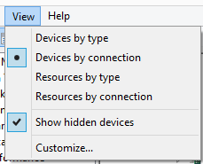
@samuel235 I changed the view like this:
Then it shows like this:
I am using version 2.8.30.0 and I downloaded them from the FTDI site.
-
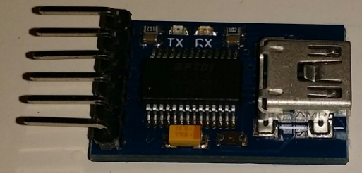
@samuel235 I'm using a Windows 8.1 PC with the Arduino 1.6.6 IDE. My FTDI adapter looks like this:
@petewill - Right okay, well my adapter is slightly different in the sense that it is all in one with a USB 2.0 adapter on the end of the board rather than a USB MiniB that you run a cable to the USB port on the PC. But apart from that the chip on-board is pretty much standard i think, from what i have found out on the internet anyway. Just for reference, this is what mine is http://www.ebay.co.uk/itm/161791651010?_trksid=p2057872.m2749.l2649&ssPageName=STRK%3AMEBIDX%3AIT.
However, when purchasing some Arduino Mini Pros, i have gotten another. http://www.ebay.co.uk/itm/161795041342?_trksid=p2057872.m2749.l2649&ssPageName=STRK%3AMEBIDX%3AIT. We will see if they're both the same functionality when it arrives.
MySensors 2.1.1
Controller - OpenHAB (Virtual Machine)
Gateway - Arduino Mega MQTT Gateway W5100 -
@petewill - Right okay, well my adapter is slightly different in the sense that it is all in one with a USB 2.0 adapter on the end of the board rather than a USB MiniB that you run a cable to the USB port on the PC. But apart from that the chip on-board is pretty much standard i think, from what i have found out on the internet anyway. Just for reference, this is what mine is http://www.ebay.co.uk/itm/161791651010?_trksid=p2057872.m2749.l2649&ssPageName=STRK%3AMEBIDX%3AIT.
However, when purchasing some Arduino Mini Pros, i have gotten another. http://www.ebay.co.uk/itm/161795041342?_trksid=p2057872.m2749.l2649&ssPageName=STRK%3AMEBIDX%3AIT. We will see if they're both the same functionality when it arrives.
-
@samuel235 A quick way to test if it's your adapter or the drivers is to plug it in to a Mac or a Linux computer and try to upload from there.