💬 Smart switch
-
Is the current physical switch connected to the arduino as well as an input button?
-
@jeremushka No, it is not connected to the arduino input. The relay is doing a 2 way switch configuration with the physical switch. As such, even though my PCB would be dead, I'm still able to control my lamp manually.
-
I've updated a new version of my design containing the comments and feedback I've received. Thanks a lot! I didn't try this design yet as I need to receive components from China. So it'll take around a month before I can test it. Anyway, I release my design already on this platform to get already some comments and feedback.
-
If i understand well to keep the normal usage of your physical switch you connect it to NC and NO of the relay and the COM pinnof the relay to the L "life" of the electrical circuit, right?
-
@jeremushka I have uploaded an image where it is explained how to connect the smart switch with the 3 way switch but I think you got the idea right.
-
@laucarlier Thank you. It is what i was thinking. for the ACS712, you connect between the live "L" connected to the COM of the relay and the neutral N ?
-
@jeremushka I connected the ACS712 in series just at the output of the switching system. I updated the schematics for the connection. Note that in the code I have delivered for reading the ACS712 might not work out of the box for you. I couldn't really make good code on that because of the instability of my previous design.
-
@laucarlier you can see a similar project here : http://domotique-diy.over-blog.com/2018/05/domotiser-un-appareil-grace-a-un-relai-v2.html
-
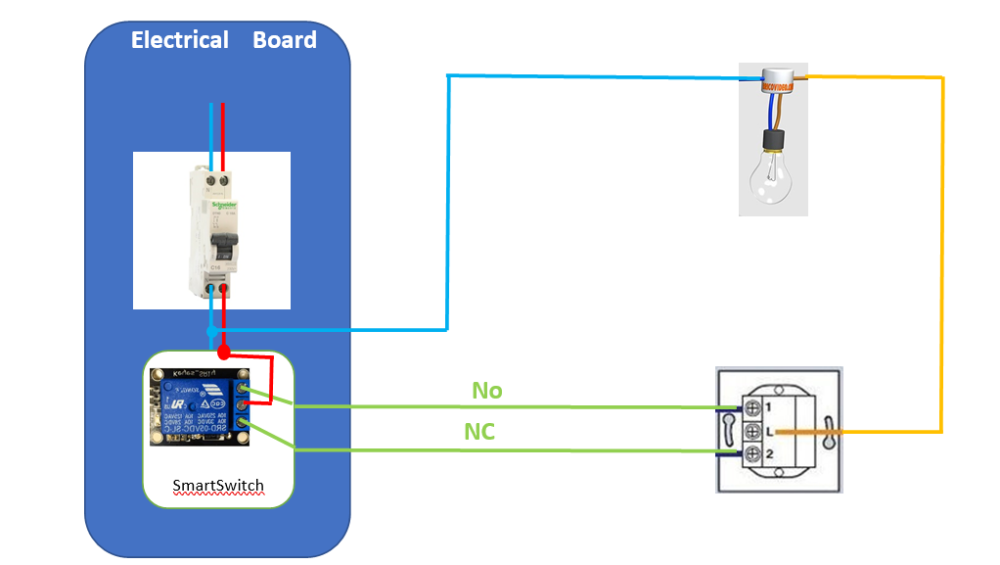
I have tried on my side the system and it is working fine. However, i have modified the connection as the following picture in order to be able to insert the system directly into the main electrical board of the house to avoid having electronic cards behind each switch.
Moreover, i connected the ACS712 on the "live" cable in serie with the COM output of the relay. In that case, i have no delay to display the status "ON", "OFF" in th controller. -
@jeremushka Nice to see that you could find the way to work with this project :) Though it looks very similar in the way I'm using my design, I'm wondering how you can connect the No and NC cables in between the smart switch and the physical switch. Since you mention that now the smart switch is inside your electrical box, does that mean that you have 2 wires traveling in between your electrical box and your switch box? I actually never though of putting a smart switch in my electrical box and I would like to know what I would need to have the smart switch installed inside the electrical box directly. In that case, the space constrain is much less.
-
@laucarlier, Behind each socket and each switch, there are 3 electric cables connected until the electrical panel. The default electrical installation was made in case one day, we want to add an automation system in the house. the three cables are: Phase, Neutral and Ground. Therefore, i can use two cables to connect them to the relay(see the diagram) directly in the electrical panel. In case of technical problem, no need to disassemble the plugs to check the electronic boards, simply open the electrical panel and control the system.
-
Else you can maybe used like this
http://domotique-diy.over-blog.com/2018/05/domotiser-un-appareil-grace-a-un-relai-v2.html -
@Aze I don't think so your project can work the same way as this one. When seeing your PCB and connection schematics, I think that the uController needs to be active so that the switch can function. In this project, even though the uController is dead or hanging, the manual switch can still activate the lamp.
-
@laucarlier Yes it's right sorry.
-
@aze No Problem ;) all the time nice to hear idea from people :)