Driving an moving coil meter whit a PWM output
-
Hello MySensor-ers,
I recently started MySensors in combination with Domoticz.
For a while I have had the idea to use some old panel meters (moving coil meters) to visualize for example (room) temperature or current consumption of electricity.
When looking around I came out on the Dimmer sketch, is this the only way to control a PWM output or are there other ways to control a PWM output which is more towards a display or meter?
second question; Does anyone have a tip to set up a script in domoticz where, for example, the measured room temperature can be sent between 0 and (max) 25 degrees to a PWM output?
thanks in advance
dzjr -
Hello MySensor-ers,
I recently started MySensors in combination with Domoticz.
For a while I have had the idea to use some old panel meters (moving coil meters) to visualize for example (room) temperature or current consumption of electricity.
When looking around I came out on the Dimmer sketch, is this the only way to control a PWM output or are there other ways to control a PWM output which is more towards a display or meter?
second question; Does anyone have a tip to set up a script in domoticz where, for example, the measured room temperature can be sent between 0 and (max) 25 degrees to a PWM output?
thanks in advance
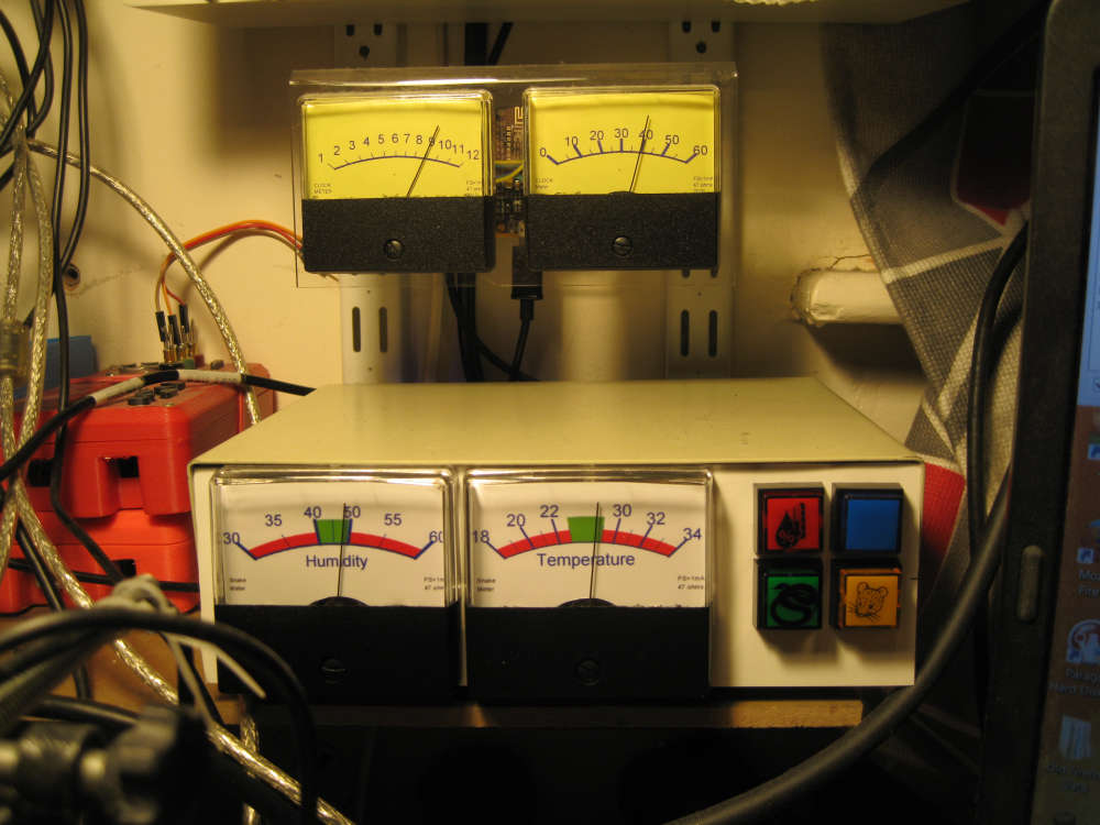
dzjr@dzjr I have several meters for quick indications.
Normally i utilize a message type of V_VAR1 to 5 as these are available for all sensor types, If it just being an information sensor then I use the S_INFO device.
I send the information to be displayed as direct units
For example for temperature I would send V_VAR1 = 26.1 as 26.1°C or -5.5
and then let the node set the display range.if you want only a linear display the following code will work,
// Enable debug prints to serial monitor
#define MY_DEBUG

// Enable and select radio type attached
#define MY_RADIO_NRF24

#include <MySensors.h>

#define SKETCH_NAME "MySensors Meter"
#define SKETCH_VERSION "v1.0"

// Meter Vars
#define METER_PIN     5
#define METER_ID      20    // whater childId your using
#define METER_MIN      0    // meter Minimum value
#define METER_MAX     30
MyMessage msg_S_INFO_VAR1(ID_S_INFO,V_VAR1);
float info_Var1 = 00.0;

void before()
{
}

void setup() {
  // put your setup code here, to run once:

}

void loop() {
  // put your main code here, to run repeatedly:

}

void receive(const MyMessage &message)
{
  if (message.type == V.VAR1) {
      info_Var1=message.getFloat();
    Serial.print("Incoming value for ID_S_INFO:");
    Serial.print(message.sensor);
    Serial.print(", V_VAR1: ");
    Serial.print(", New status: ");
    Serial.println(info_Var1,1);
    updateMeter0(info_Var1);
  }
}


void updateMeter0(float meterInput=0){
// Meter 0   this uses the input value and simple maping
// Note The map() function uses integer math so will not generate fractions, so can be helpful to multiply input values
// ie using input temperature value 0 to 30°C  So multiply by 10 to get 0-to 300
int16_t max_Output=   255;   // maximum PWM Value, 255 for Arduino Uno,  1023 for ESP8266
meterInput = meterInput *10;
analogWrite(meter_pin, map(meterInput,meter_MIN, meter_MAX, 0, max_Output )) ;  // map to Max PWM Level
}
However i like to have arbitrary scales so normally use a look-up array for the pwm values. as used in the meters shown.
-
Thank you for your reply.
It is indeed what I mean and wants to make.
I have several old meters with various scales, but not all scales are usable, but that does not have to be a problem.If you like it, I will use your sketch as an example.
I myself had not even thought of arranging the minimum / maximum value in the arduino.I'm going to set up a test soon.
Incidentally beautifully composed box with the meters and lights!
When I have finished I will post a photo!
thanks again for your push in the right direction !!
dzjr
-
@dzjr I also have various old meters, Some have a sealed movement so unable to change the scales.
Below is my meter showing time since last coffee.

@hard-shovel That would be the cold coffee with cream with a certain Guinness ais quoi? ;)
Hello! It looks like you're interested in this conversation, but you don't have an account yet.
Getting fed up of having to scroll through the same posts each visit? When you register for an account, you'll always come back to exactly where you were before, and choose to be notified of new replies (either via email, or push notification). You'll also be able to save bookmarks and upvote posts to show your appreciation to other community members.
With your input, this post could be even better 💗
Register Login