OLED Scene controller
-
So I have been out of touch with the MySensors world for a while now due to some other things that have consumed me. I had the need a couple days ago to set up a new light switch for my master bedroom and made the decision to use one of my old projects that I never fully finished; my OLED scene controller board. So the dilemma that I have is that I am trying to set this up so that I can push some data to it from my Vera controller to display on the OLED module. I would like to make this so that I can use it for any type of data that I choose to display, for flexibility reasons. My issue is that I am trying to figure out how I can push data to the node that would be displayed. My initial thought was to use V_VAR1 - V_VAR5 giving me 5 lines of data that I can display.
Backing up a slight bit, I have code written that will present the buttons to the controller and I have basic ON/OFF control to Vera. I also have a basic text driver for the OLED display and can display text of my choice. My problem comes in with the transfer of text to the node. Below is the code as I have it written so far.
// Enable debug prints
//#define MY_DEBUG
//#define AUTO
//#define DEBUG

// Enable and select radio type attached
#define MY_RADIO_NRF24
//#define MY_RADIO_RFM69
//#define MY_RS485

//#define MY_REPEATER_FEATURE

#include <SPI.h>
#include <MySensors.h>
#include <Wire.h>
//Uncomment the following lines if using the I2C version of the display
#include "SSD1306Ascii.h"
#include "SSD1306AsciiWire.h"
#include <avr/pgmspace.h>

#include <Keypad.h>

#define I2C_ADDRESS 0x3C
#define RST_PIN -1
SSD1306AsciiWire display;

int timer_count = 0;

bool metric = false;

#define CHILD_ID_ONOFF1       0
#define CHILD_ID_ONOFF2       1
#define CHILD_ID_ONOFF3       2
#define CHILD_ID_DISPLAY      3

//Define the number of rows and columns for the keypad
const byte ROWS = 3;
const byte COLS = 2;

//Map the keys for the keypad
char keys[ROWS][COLS] = {
  {'1','2'},
  {'3','4'},
  {'5','6'}
};
//Arduino pins for the rows and columns in the button matrix. Choose the pins based
//on your chosen configuration of buttons

//    |  D8  |  D7  |  D6
//----|------|------|-------
// D3 |  1   |  2   |  3
//----|------|------|-------
// D4 |  4   |  5   |  6
//----|------|------|-------
// D5 |  7   |  8   |  9
//    |      |      |
byte rowPins[ROWS] = { 4, 5, 6 };
byte colPins[COLS] = { 3, 7 };

char* rowDef[ROWS] = { "Table Lamps", "Ceiling Fan", "Ceiling Light" };

int pos = 0;
int fontsize = 1;

int tMax = 30000;
int switchTimer = 0;

char* roomTemp = "70";
char* outsideTemp = "45";

// Create the Keypad
Keypad kpd = Keypad( makeKeymap(keys), rowPins, colPins, ROWS, COLS );

//Define the switch message transports. These will depend on the key configuration you
//choose and how you need the buttons to function
MyMessage onOff1(CHILD_ID_ONOFF1, V_STATUS);
MyMessage onOff2(CHILD_ID_ONOFF2, V_STATUS);
MyMessage onOff3(CHILD_ID_ONOFF3, V_STATUS);
MyMessage msgDisplay(CHILD_ID_DISPLAY, V_TEXT);
MyMessage msgDispLn1(CHILD_ID_DISPLAY, V_VAR1);
MyMessage msgDispLn2(CHILD_ID_DISPLAY, V_VAR2);
MyMessage msgDispLn3(CHILD_ID_DISPLAY, V_VAR3);
MyMessage msgDispLn4(CHILD_ID_DISPLAY, V_VAR4);
MyMessage msgDispLn5(CHILD_ID_DISPLAY, V_VAR5);


void presentation()
{
  //Send the sketch version information to the gateway
  sendSketchInfo("OLEDSwitch", "1.0");

  //Register allse nsors to gw (they will be created as child devices)
  present(CHILD_ID_ONOFF1, S_BINARY);
  present(CHILD_ID_ONOFF2, S_BINARY);
  present(CHILD_ID_ONOFF3, S_BINARY);
  present(CHILD_ID_DISPLAY, S_INFO);
}

void setup() {
  // put your setup code here, to run once:
  #if RST_PIN >= 0
    display.begin(&Adafruit128x64, I2C_ADDRESS, RST_PIN);
  #else // RST_PIN >= 0
    display.begin(&Adafruit128x64, I2C_ADDRESS);
  #endif // RST_PIN >= 0

  Serial.begin(9600);
  display.clear();
  display.setFont(Adafruit5x7);
  Serial.println("Starting...");
}

void loop() {
  // put your main code here, to run repeatedly:
  scanKeys();

  updateDisplay();
}

void receive( const MyMessage &message ) {
  switch (message.sensor) {
    case CHILD_ID_ONOFF1:
      send(onOff1.set(atoi(message.data)));
      break;
    case CHILD_ID_ONOFF2:
      send(onOff2.set(atoi(message.data)));
      break;
    case CHILD_ID_ONOFF3:
      send(onOff3.set(atoi(message.data)));
      break;
  }
  if (message.type == V_VAR1) {
    outsideTemp = (char*)message.data;
  }

  if (message.type == V_VAR2) {
    roomTemp = (char*)message.data;
  }
}

void scanKeys() {
  char key = kpd.getKey();
  if(key)  // Check for a valid key.
  {
    switch (key)
    {
      case '1': //Bottom switch off
        send(onOff1.set("0"));
        displaySwitch(rowDef[0], "Off");
        break;
      case '2': //Bottom switch on
        send(onOff1.set("1"));
        displaySwitch(rowDef[0], "On");
        break;
      case '3': //Middle switch off
        send(onOff2.set("0"));
        displaySwitch(rowDef[1], "Off");
        break;
      case '4': //Middle switch on
        send(onOff2.set("1"));
        displaySwitch(rowDef[1], "On");
        break;
      case '5': //Top switch off
        send(onOff3.set("0"));
        displaySwitch(rowDef[2], "Off");
        break;
      case '6': //Top switch on
        send(onOff3.set("1"));
        displaySwitch(rowDef[2], "On");
        break;
      default:
        Serial.println(key);
    }
  }
}


void updateDisplay() {
  if (switchTimer > 0) {
    switchTimer --;
  } else if (switchTimer == 0) {
    display.clear();
    switchTimer = -1;
  } else {
    if (timer_count == 0) {
      displayTemp(roomTemp, "Room");
    } else if (timer_count == tMax/2) {
      displayTemp(outsideTemp, "Outside");
    }

    timer_count++;
    if (timer_count > tMax) timer_count = 0;
  }
}


void displayTemp(char* temp, char* title) {
  display.setFont(Adafruit5x7);
  display.home();
  display.set1X();
  //display.clearToEOL();
  if (title == "Room") {
  display.setCursor(10,0);
    display.print(" ");
  } else if (title == "Outside") {
    display.setCursor(10,0);
  }
  display.print(title);
  display.println(" Temperature     ");
  display.set2X();
  display.setCursor(50,4);
  display.print(temp);
  display.print((char)247);
  display.println((metric)?"C":"F");
}

void displaySwitch(char* name, char* state) {
  display.setFont(Adafruit5x7);
  display.clear();
  display.set1X();
  display.setCursor(65-(strlen(name)*3),3);
  display.println(name);
  display.set2X();
  display.setCursor(55-(strlen(state)*1.25),5);
  display.println(state);
  switchTimer = 15000;
}
I am thinking that I am doing something wrong in how I present the V_VAR1-5 for me to send the data to. So I create a child to handle the display and under it I am creating the V_VAR1-5 attributes with these lines:
MyMessage msgDisplay(CHILD_ID_DISPLAY, V_TEXT);
MyMessage msgDispLn1(CHILD_ID_DISPLAY, V_VAR1);
MyMessage msgDispLn2(CHILD_ID_DISPLAY, V_VAR2);
MyMessage msgDispLn3(CHILD_ID_DISPLAY, V_VAR3);
MyMessage msgDispLn4(CHILD_ID_DISPLAY, V_VAR4);
MyMessage msgDispLn5(CHILD_ID_DISPLAY, V_VAR5);
The text node child shows up in Vera, but when I look in the Variables tab under advanced in the child properties, there is nothing there. I tried to somewhat mimic how the irrigation controller code does it for the zone settings, but it's not working.
Feel free to ask questions for further clarification if needed. Any help you can give is appreciated.
-
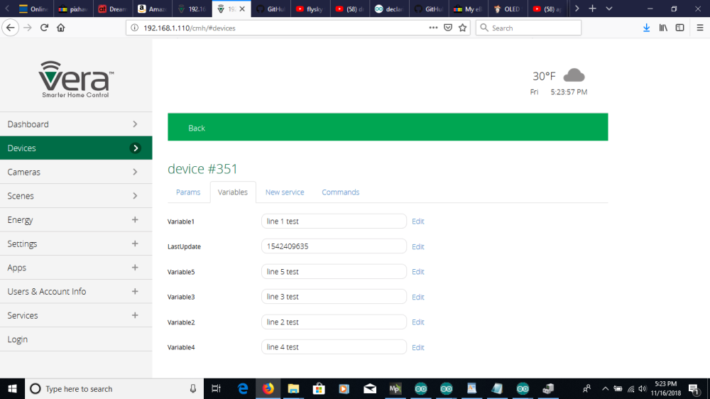
I have noticed that in the latest Vera firmware if a variable has no value it does not show up in the Advanced -> Variables tab.
Try writing some value manually from Apps -> Develop apps -> test loop code (here is an example):
luup.call_action("urn:upnp-arduino-cc:serviceId:arduino1", "SendCommand", {radioId="11;3", variableId="VAR_4", value=1}, 24)
24 in the example is the Id of the MySensors plugin Main device.
11;3 in the example is altid of the sensor node device.After writing and refreshing of browser (Ctrl + F5) you should see the variables under Advanced -> Variables tab
The command should also send the value to your child node.
@korttoma So that worked to a point. When I sent test luup code to all 5 variables, I can now see them:
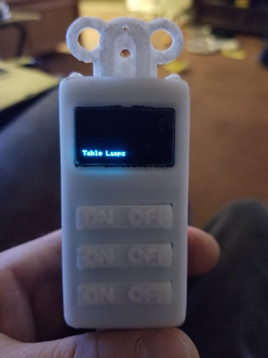
Here is the current updated code that I am running in these examples:// Enable debug prints //#define MY_DEBUG //#define AUTO //#define DEBUG // Enable and select radio type attached #define MY_RADIO_NRF24 //#define MY_RADIO_RFM69 //#define MY_RS485 //#define MY_REPEATER_FEATURE #include <SPI.h> #include <MySensors.h> #include <Wire.h> //Uncomment the following lines if using the I2C version of the display #include "SSD1306Ascii.h" #include "SSD1306AsciiWire.h" #include <avr/pgmspace.h> #include <Keypad.h> #define I2C_ADDRESS 0x3C #define RST_PIN -1 SSD1306AsciiWire display; int timer_count = 0; bool metric = false; #define CHILD_ID_ONOFF1 0 #define CHILD_ID_ONOFF2 1 #define CHILD_ID_ONOFF3 2 #define CHILD_ID_DISPLAY 3 //Define the number of rows and columns for the keypad const byte ROWS = 3; const byte COLS = 2; //Map the keys for the keypad char keys[ROWS][COLS] = { {'1','2'}, {'3','4'}, {'5','6'} }; //Arduino pins for the rows and columns in the button matrix. Choose the pins based //on your chosen configuration of buttons // | D8 | D7 | D6 //----|------|------|------- // D3 | 1 | 2 | 3 //----|------|------|------- // D4 | 4 | 5 | 6 //----|------|------|------- // D5 | 7 | 8 | 9 // | | | byte rowPins[ROWS] = { 4, 5, 6 }; byte colPins[COLS] = { 3, 7 }; char* rowDef[ROWS] = { "Table Lamps", "Ceiling Fan", "Ceiling Light" }; char* disp[x] = { "", "", "", "", "" }; int pos = 0; int fontsize = 1; int tMax = 30000; int switchTimer = 0; // Create the Keypad Keypad kpd = Keypad( makeKeymap(keys), rowPins, colPins, ROWS, COLS ); //Define the switch message transports. These will depend on the key configuration you //choose and how you need the buttons to function MyMessage onOff1(CHILD_ID_ONOFF1, V_STATUS); MyMessage onOff2(CHILD_ID_ONOFF2, V_STATUS); MyMessage onOff3(CHILD_ID_ONOFF3, V_STATUS); MyMessage msgDisplay(CHILD_ID_DISPLAY, V_TEXT); MyMessage msgDispLn1(CHILD_ID_DISPLAY, V_VAR1); MyMessage msgDispLn2(CHILD_ID_DISPLAY, V_VAR2); MyMessage msgDispLn3(CHILD_ID_DISPLAY, V_VAR3); MyMessage msgDispLn4(CHILD_ID_DISPLAY, V_VAR4); MyMessage msgDispLn5(CHILD_ID_DISPLAY, V_VAR5); void presentation() { //Send the sketch version information to the gateway sendSketchInfo("OLEDSwitch", "1.0"); //Register allse nsors to gw (they will be created as child devices) present(CHILD_ID_ONOFF1, S_BINARY); present(CHILD_ID_ONOFF2, S_BINARY); present(CHILD_ID_ONOFF3, S_BINARY); present(CHILD_ID_DISPLAY, S_INFO); } void setup() { // put your setup code here, to run once: #if RST_PIN >= 0 display.begin(&Adafruit128x64, I2C_ADDRESS, RST_PIN); #else // RST_PIN >= 0 display.begin(&Adafruit128x64, I2C_ADDRESS); #endif // RST_PIN >= 0 Serial.begin(9600); display.clear(); display.setFont(Adafruit5x7); Serial.println("Starting..."); } void loop() { // put your main code here, to run repeatedly: scanKeys(); updateDisplay(); } void receive( const MyMessage &message ) { switch (message.sensor) { case CHILD_ID_ONOFF1: send(onOff1.set(atoi(message.data))); break; case CHILD_ID_ONOFF2: send(onOff2.set(atoi(message.data))); break; case CHILD_ID_ONOFF3: send(onOff3.set(atoi(message.data))); break; } if (message.type == V_VAR1) { disp[1] = (char*)message.data; } if (message.type == V_VAR2) { disp[2] = (char*)message.data; } if (message.type == V_VAR3) { disp[3] = (char*)message.data; } if (message.type == V_VAR4) { disp[4] = (char*)message.data; } if (message.type == V_VAR5) { disp[5] = (char*)message.data; } } void scanKeys() { char key = kpd.getKey(); if(key) // Check for a valid key. { switch (key) { case '1': //Bottom switch off send(onOff1.set("0")); displaySwitch(rowDef[0], "Off"); break; case '2': //Bottom switch on send(onOff1.set("1")); displaySwitch(rowDef[0], "On"); break; case '3': //Middle switch off send(onOff2.set("0")); displaySwitch(rowDef[1], "Off"); break; case '4': //Middle switch on send(onOff2.set("1")); displaySwitch(rowDef[1], "On"); break; case '5': //Top switch off send(onOff3.set("0")); displaySwitch(rowDef[2], "Off"); break; case '6': //Top switch on send(onOff3.set("1")); displaySwitch(rowDef[2], "On"); break; default: Serial.println(key); } } } void updateDisplay() { if (switchTimer > 0) { switchTimer --; } else if (switchTimer == 0) { display.clear(); switchTimer = -1; } else { display.setFont(Adafruit5x7); display.home(); display.set1X(); display.println(disp[1]); display.set2X(); display.println(disp[2]); display.println(disp[3]); display.println(disp[4]); display.set1X(); display.println(disp[5]); } } /*void updateDisplay() { if (switchTimer > 0) { switchTimer --; } else if (switchTimer == 0) { display.clear(); switchTimer = -1; } else { if (timer_count == 0) { displayTemp(roomTemp, "Room"); } else if (timer_count == tMax/2) { displayTemp(outsideTemp, "Outside"); } timer_count++; if (timer_count > tMax) timer_count = 0; } }*/ void displayTemp(char* temp, char* title) { display.setFont(Adafruit5x7); display.home(); display.set1X(); //display.clearToEOL(); if (title == "Room") { display.setCursor(10,0); display.print(" "); } else if (title == "Outside") { display.setCursor(10,0); } display.print(title); display.println(" Temperature "); display.set2X(); display.setCursor(50,4); display.print(temp); display.print((char)247); display.println((metric)?"C":"F"); } void displaySwitch(char* name, char* state) { display.setFont(Adafruit5x7); display.clear(); display.set1X(); display.setCursor(65-(strlen(name)*3),3); display.println(name); display.set2X(); display.setCursor(55-(strlen(state)*1.25),5); display.println(state); switchTimer = 15000; }So the first problem I have is that when I boot the node, line 5 shows "Table Lamps" which is the text from the first element of char* array rowDef from line 61.
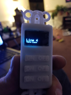
If I then send this test luup code:luup.call_action("urn:upnp-arduino-cc:serviceId:arduino1", "SendCommand", {radioId="24;3", variableId="VAR_4", value="Line 4"}, 27)I see this:
If I then send this:luup.call_action("urn:upnp-arduino-cc:serviceId:arduino1", "SendCommand", {radioId="24;3", variableId="VAR_2", value="Line 2"}, 27)I get this:
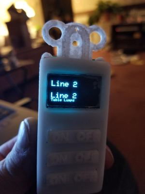
It prints "line 2" on both line 2 and line 4 with line 5 still reading "Table Lamps". If I then test this:luup.call_action("urn:upnp-arduino-cc:serviceId:arduino1", "SendCommand", {radioId="24;3", variableId="VAR_5", value="Line 5"}, 27)Then the display shows this:
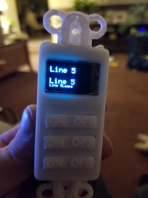
It appears that I may have something wrong in my Receive method that processes the incoming V_VAR strings. It could also have something to do with my disp[] variable array. I am also stumped with the "Table Lamps" text.I am trying to stay away from using String variables which is why I am using char*.
Thanks in advance for any help.
-
So with a bit of testing, I have figured out my issue. I was using a pointer to a character array, when I should have been using just a straight character array.
Here is my updated code that works.// Enable debug prints //#define MY_DEBUG //#define AUTO //#define DEBUG // Enable and select radio type attached #define MY_RADIO_NRF24 //#define MY_RADIO_RFM69 //#define MY_RS485 //#define MY_REPEATER_FEATURE #include <SPI.h> #include <MySensors.h> #include <Wire.h> #include <string.h> //Uncomment the following lines if using the I2C version of the display #include "SSD1306Ascii.h" #include "SSD1306AsciiWire.h" #include <avr/pgmspace.h> #include <Keypad.h> #define I2C_ADDRESS 0x3C #define RST_PIN -1 SSD1306AsciiWire display; int timer_count = 0; bool metric = false; #define CHILD_ID_ONOFF1 0 #define CHILD_ID_ONOFF2 1 #define CHILD_ID_ONOFF3 2 #define CHILD_ID_DISPLAY 3 //Define the number of rows and columns for the keypad const byte ROWS = 3; const byte COLS = 2; //Map the keys for the keypad char keys[ROWS][COLS] = { {'1','2'}, {'3','4'}, {'5','6'} }; //Arduino pins for the rows and columns in the button matrix. Choose the pins based //on your chosen configuration of buttons // | D8 | D7 | D6 //----|------|------|------- // D3 | 1 | 2 | 3 //----|------|------|------- // D4 | 4 | 5 | 6 //----|------|------|------- // D5 | 7 | 8 | 9 // | | | byte rowPins[ROWS] = { 4, 5, 6 }; byte colPins[COLS] = { 3, 7 }; char* rowDef[ROWS] = { "Table Lamps", "Ceiling Fan", "Ceiling Light" }; char disp1[] = ""; char disp2[] = ""; char disp3[] = ""; char disp4[] = ""; char disp5[] = ""; char disp[6][23]; // = { disp1, disp2, disp3, disp4, disp5 }; int pos = 0; int fontsize = 1; int tMax = 30000; int switchTimer = 0; // Create the Keypad Keypad kpd = Keypad( makeKeymap(keys), rowPins, colPins, ROWS, COLS ); //Define the switch message transports. These will depend on the key configuration you //choose and how you need the buttons to function MyMessage onOff1(CHILD_ID_ONOFF1, V_STATUS); MyMessage onOff2(CHILD_ID_ONOFF2, V_STATUS); MyMessage onOff3(CHILD_ID_ONOFF3, V_STATUS); MyMessage msgDisplay(CHILD_ID_DISPLAY, V_TEXT); MyMessage msgDispLn1(CHILD_ID_DISPLAY, V_VAR1); MyMessage msgDispLn2(CHILD_ID_DISPLAY, V_VAR2); MyMessage msgDispLn3(CHILD_ID_DISPLAY, V_VAR3); MyMessage msgDispLn4(CHILD_ID_DISPLAY, V_VAR4); MyMessage msgDispLn5(CHILD_ID_DISPLAY, V_VAR5); void presentation() { //Send the sketch version information to the gateway sendSketchInfo("OLEDSwitch", "1.0"); //Register allse nsors to gw (they will be created as child devices) present(CHILD_ID_ONOFF1, S_BINARY); present(CHILD_ID_ONOFF2, S_BINARY); present(CHILD_ID_ONOFF3, S_BINARY); present(CHILD_ID_DISPLAY, S_INFO); } void setup() { // put your setup code here, to run once: #if RST_PIN >= 0 display.begin(&Adafruit128x64, I2C_ADDRESS, RST_PIN); #else // RST_PIN >= 0 display.begin(&Adafruit128x64, I2C_ADDRESS); #endif // RST_PIN >= 0 Serial.begin(9600); display.clear(); Serial.println("Starting..."); } void loop() { // put your main code here, to run repeatedly: scanKeys(); updateDisplay(); } void receive( const MyMessage &message ) { switch (message.sensor) { case CHILD_ID_ONOFF1: send(onOff1.set(atoi(message.data))); break; case CHILD_ID_ONOFF2: send(onOff2.set(atoi(message.data))); break; case CHILD_ID_ONOFF3: send(onOff3.set(atoi(message.data))); break; case CHILD_ID_DISPLAY: int var = 0; if (message.type == V_VAR1) { strncpy(disp[1], (char*)message.data, 22); } else if (message.type == V_VAR2) { strncpy(disp[2], (char*)message.data, 22); } else if (message.type == V_VAR3) { strncpy(disp[3], (char*)message.data, 22); } else if (message.type == V_VAR4) { strncpy(disp[4], (char*)message.data, 22); } else if (message.type == V_VAR5) { strncpy(disp[5], (char*)message.data, 22); } break; } Serial.print("disp1 = "); Serial.println(disp[1]); Serial.print("disp2 = "); Serial.println(disp[2]); Serial.print("disp3 = "); Serial.println(disp[3]); Serial.print("disp4 = "); Serial.println(disp[4]); Serial.print("disp5 = "); Serial.println(disp[5]); Serial.println("----------------------------"); } void scanKeys() { char key = kpd.getKey(); if(key) // Check for a valid key. { switch (key) { case '1': //Bottom switch off send(onOff1.set("0")); displaySwitch(rowDef[0], "Off"); break; case '2': //Bottom switch on send(onOff1.set("1")); displaySwitch(rowDef[0], "On"); break; case '3': //Middle switch off send(onOff2.set("0")); displaySwitch(rowDef[1], "Off"); break; case '4': //Middle switch on send(onOff2.set("1")); displaySwitch(rowDef[1], "On"); break; case '5': //Top switch off send(onOff3.set("0")); displaySwitch(rowDef[2], "Off"); break; case '6': //Top switch on send(onOff3.set("1")); displaySwitch(rowDef[2], "On"); break; default: Serial.println(key); } } } void updateDisplay() { if (switchTimer > 0) { switchTimer --; } else if (switchTimer == 0) { display.clear(); switchTimer = -1; } else { display.setFont(Adafruit5x7); display.home(); for(int i = 1; i <= 5; i++) { if ( i == 1 || i == 5) { display.set1X(); }else { display.set2X(); } display.println(disp[i]); } } } void displayTemp(char* temp, char* title) { display.setFont(Adafruit5x7); display.home(); display.set1X(); //display.clearToEOL(); if (title == "Room") { display.setCursor(10,0); display.print(" "); } else if (title == "Outside") { display.setCursor(10,0); } display.print(title); display.println(" Temperature "); display.set2X(); display.setCursor(50,4); display.print(temp); display.print((char)247); display.println((metric)?"C":"F"); } void displaySwitch(char* name, char* state) { display.setFont(Adafruit5x7); display.clear(); display.set1X(); display.setCursor(65-(strlen(name)*3),3); display.println(name); display.set2X(); display.setCursor(55-(strlen(state)*1.25),5); display.println(state); switchTimer = 15000; }Now, if anyone has any ideas on how I can program a Vera scene or through PLEG to send data to the different V_VARs, that would help alot. For now I would just look at switching between two temp values every 5 to 10 seconds or so, that would work. All I would need to know is how I can execute some luup code at a certain interval.
Thanks @korttoma for the luup test code to set the V_Vars.
-
So through a ton of googling and experimenting I got the whole thing working. I ended up using a Vera scene set to a 16 second interval th at runs this lua script:
luup.call_action("urn:upnp-arduino-cc:serviceId:arduino1", "SendCommand", {radioId="24;3", variableId="VAR_1", value=" Outside Temp "}, 27) local CurrentTemp= luup.variable_get("urn:upnp-org:serviceId:TemperatureSensor1","CurrentTemperature", 26) luup.call_action("urn:upnp-arduino-cc:serviceId:arduino1", "SendCommand", {radioId="24;3", variableId="VAR_3", value=" "..CurrentTemp.." F "}, 27) luup.sleep( 1000 ) luup.sleep( 1000 ) luup.sleep( 1000 ) luup.sleep( 1000 ) luup.sleep( 1000 ) luup.sleep( 1000 ) luup.sleep( 1000 ) luup.sleep( 1000 ) luup.call_action("urn:upnp-arduino-cc:serviceId:arduino1", "SendCommand", {radioId="24;3", variableId="VAR_1", value=" Bedroom Temp "}, 27) local CurrentTemp= luup.variable_get("urn:upnp-org:serviceId:TemperatureSensor1","CurrentTemperature", 23) luup.call_action("urn:upnp-arduino-cc:serviceId:arduino1", "SendCommand", {radioId="24;3", variableId="VAR_3", value=" "..CurrentTemp.." F "}, 27)The reason for the multiple luup.sleep() calls is that I read that if you do a sleep call longer than 1 second, that it can cause the luup engine to restart thinking that it hung. There are 8 luup.sleep() calls to delay 8 seconds in between sending the two temp values.
Here is my final MySensors sketch for the switch:
// Enable debug prints //#define MY_DEBUG //#define AUTO //#define DEBUG // Enable and select radio type attached #define MY_RADIO_NRF24 //#define MY_RADIO_RFM69 //#define MY_RS485 //#define MY_REPEATER_FEATURE #include <SPI.h> #include <MySensors.h> #include <Wire.h> #include <string.h> //Uncomment the following lines if using the I2C version of the display #include "SSD1306Ascii.h" #include "SSD1306AsciiWire.h" #include <avr/pgmspace.h> #include <Keypad.h> #define I2C_ADDRESS 0x3C #define RST_PIN -1 SSD1306AsciiWire display; int timer_count = 0; bool metric = false; #define CHILD_ID_ONOFF1 0 #define CHILD_ID_ONOFF2 1 #define CHILD_ID_ONOFF3 2 #define CHILD_ID_DISPLAY 3 //Define the number of rows and columns for the keypad const byte ROWS = 3; const byte COLS = 2; //Map the keys for the keypad char keys[ROWS][COLS] = { {'1','2'}, {'3','4'}, {'5','6'} }; //Arduino pins for the rows and columns in the button matrix. Choose the pins based //on your chosen configuration of buttons // | D8 | D7 | D6 //----|------|------|------- // D3 | 1 | 2 | 3 //----|------|------|------- // D4 | 4 | 5 | 6 //----|------|------|------- // D5 | 7 | 8 | 9 // | | | byte rowPins[ROWS] = { 4, 5, 6 }; byte colPins[COLS] = { 3, 7 }; char* rowDef[ROWS] = { "Table Lamps", "Ceiling Fan", "Ceiling Light" }; char disp1[] = ""; char disp2[] = ""; char disp3[] = ""; char disp4[] = ""; char disp5[] = ""; char disp[6][23]; // = { disp1, disp2, disp3, disp4, disp5 }; int pos = 0; int fontsize = 1; int tMax = 30000; int switchTimer = 0; // Create the Keypad Keypad kpd = Keypad( makeKeymap(keys), rowPins, colPins, ROWS, COLS ); //Define the switch message transports. These will depend on the key configuration you //choose and how you need the buttons to function MyMessage onOff1(CHILD_ID_ONOFF1, V_STATUS); MyMessage onOff2(CHILD_ID_ONOFF2, V_STATUS); MyMessage onOff3(CHILD_ID_ONOFF3, V_STATUS); MyMessage msgDisplay(CHILD_ID_DISPLAY, V_TEXT); MyMessage msgDispLn1(CHILD_ID_DISPLAY, V_VAR1); MyMessage msgDispLn2(CHILD_ID_DISPLAY, V_VAR2); MyMessage msgDispLn3(CHILD_ID_DISPLAY, V_VAR3); MyMessage msgDispLn4(CHILD_ID_DISPLAY, V_VAR4); MyMessage msgDispLn5(CHILD_ID_DISPLAY, V_VAR5); void presentation() { //Send the sketch version information to the gateway sendSketchInfo("OLEDSwitch", "1.0"); //Register allse nsors to gw (they will be created as child devices) present(CHILD_ID_ONOFF1, S_BINARY); present(CHILD_ID_ONOFF2, S_BINARY); present(CHILD_ID_ONOFF3, S_BINARY); present(CHILD_ID_DISPLAY, S_INFO); } void setup() { // put your setup code here, to run once: #if RST_PIN >= 0 display.begin(&Adafruit128x64, I2C_ADDRESS, RST_PIN); #else // RST_PIN >= 0 display.begin(&Adafruit128x64, I2C_ADDRESS); #endif // RST_PIN >= 0 Serial.begin(9600); display.clear(); Serial.println("Starting..."); } void loop() { // put your main code here, to run repeatedly: scanKeys(); updateDisplay(); } void receive( const MyMessage &message ) { switch (message.sensor) { case CHILD_ID_ONOFF1: send(onOff1.set(atoi(message.data))); break; case CHILD_ID_ONOFF2: send(onOff2.set(atoi(message.data))); break; case CHILD_ID_ONOFF3: send(onOff3.set(atoi(message.data))); break; case CHILD_ID_DISPLAY: int var = 0; if (message.type == V_VAR1) { strncpy(disp[1], (char*)message.data, 22); } else if (message.type == V_VAR2) { strncpy(disp[2], (char*)message.data, 22); } else if (message.type == V_VAR3) { strncpy(disp[3], (char*)message.data, 22); } else if (message.type == V_VAR4) { strncpy(disp[4], (char*)message.data, 22); } else if (message.type == V_VAR5) { strncpy(disp[5], (char*)message.data, 22); } break; } Serial.print("disp1 = "); Serial.println(disp[1]); Serial.print("disp2 = "); Serial.println(disp[2]); Serial.print("disp3 = "); Serial.println(disp[3]); Serial.print("disp4 = "); Serial.println(disp[4]); Serial.print("disp5 = "); Serial.println(disp[5]); Serial.println("----------------------------"); } void scanKeys() { char key = kpd.getKey(); if(key) // Check for a valid key. { switch (key) { case '1': //Bottom switch off send(onOff1.set("0")); displaySwitch(rowDef[0], "Off"); break; case '2': //Bottom switch on send(onOff1.set("1")); displaySwitch(rowDef[0], "On"); break; case '3': //Middle switch off send(onOff2.set("0")); displaySwitch(rowDef[1], "Off"); break; case '4': //Middle switch on send(onOff2.set("1")); displaySwitch(rowDef[1], "On"); break; case '5': //Top switch off send(onOff3.set("0")); displaySwitch(rowDef[2], "Off"); break; case '6': //Top switch on send(onOff3.set("1")); displaySwitch(rowDef[2], "On"); break; default: Serial.println(key); } } } void updateDisplay() { if (switchTimer > 0) { switchTimer --; } else if (switchTimer == 0) { display.clear(); switchTimer = -1; } else { display.setFont(Adafruit5x7); display.home(); for(int i = 1; i <= 5; i++) { if ( i == 1 || i == 5) { display.set1X(); }else { display.set2X(); } display.println(disp[i]); } } } void displayTemp(char* temp, char* title) { display.setFont(Adafruit5x7); display.home(); display.set1X(); //display.clearToEOL(); if (title == "Room") { display.setCursor(10,0); display.print(" "); } else if (title == "Outside") { display.setCursor(10,0); } display.print(title); display.println(" Temperature "); display.set2X(); display.setCursor(50,4); display.print(temp); display.print((char)247); display.println((metric)?"C":"F"); } void displaySwitch(char* name, char* state) { display.setFont(Adafruit5x7); display.clear(); display.set1X(); display.setCursor(65-(strlen(name)*3),3); display.println(name); display.set2X(); display.setCursor(55-(strlen(state)*1.25),5); display.println(state); switchTimer = 15000; }This is the text only library I used for the SDD1306 OLED display. https://github.com/greiman/SSD1306Ascii
Finally, here is a youtube video of the whole thing working.
https://www.youtube.com/watch?v=d1T8SvRpiSkIf there is interest in this project, feel free to message me for more details or with any questins
-
I now have this switch design posted on thingiverse for anyone that is interested.
https://www.thingiverse.com/thing:3227603 -
Very cool!
