Navigation

    • Register
    • Login
    • OpenHardware.io
    • Categories
    • Recent
    • Tags
    • Popular
    1. Home
    2. ayo
    3. Best
    • Profile
    • Following
    • Followers
    • Topics
    • Posts
    • Best
    • Groups

    Best posts made by ayo

    • RE: arduino mega nrf wiring

      Just connect it like this
      0_1474672146639_megaConnectioon.JPG
      alt text

      That should Work.

      In your arduino code add the following before the #include <SPI.h>
      #include <MySensors.h>

      // Pin Confuguration for Arduino Mega
      #define MY_RF24_CE_PIN 40
      #define MY_RF24_CS_PIN 53
      

      and you are good. 🙂

      posted in Hardware
      ayo
      ayo
    • RE: [Solved] MySensors node not working, Trouble finding parent node

      Okay....So after some trial I finally got the whole system to work now. The problem was from the node device, I re-soldered everything on the node part and it works flawlessly. I have even try adding more nodes to it which works without problem too. Now I will proceed to building my own Arduino based controller.
      Thanks I guess 🙂

      posted in Troubleshooting
      ayo
      ayo
    • RE: arduino mega nrf wiring

      @Edoardo-Macrì It should work irrespective of the library version. Cross check your connection again, don't forget about capacitors too and lastly make sure you add that #define part into your code.

      posted in Hardware
      ayo
      ayo
    • [Solved] MySensors node not working, Trouble finding parent node

      Hello,
      Have been having problem trying to get atleast 2 nodes to work properly and I can't seems to figure out the problem/solution.
      I have the Ardunio Uno as my serial gateway connected to the NRF24L01+ radio with a 10uf cap using the 2.0 GatewaySerial example (unchanged and even changed :)).
      Have checked the pins for continuity and voltage drop where everything seems okay.
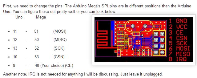
      On the sensor node side, I have an Arduino Mega 2560 connected to the same NRF24L01+ 2.4GHz radio powered by an external 3.3V regulator.
      On the sensor node am running the default dust sensors code adding just a modification of static node id of 6 and arduino mega CS and CE radio pins

      What I've tried: Swapping the codes between the 2 arduino boards, trying out another type of the nrf24l01+ radio, moving the node further away from the gateway, moving the node and gateway closer, trying other example similar codes for the sensor node.

      I don't have a controller, so I've hard-coded the node ID and parent id with #define MY_NODE_ID 6 and #define MY_PARENT_NODE_ID 0 for the sensor node not sure if that's necessary for the gateway device.
      At the end am hoping to build my own limited controller powered by the Arduino mega or Due incorporating the Nextion touch Display for User Interface.

      So, when I start the two monitors up within a few seconds of each other (gateway first), here's the output of the gateway:

      Gateway log messages
      
      0;255;3;0;9;Starting gateway (RNNGA-, 2.0.0)
      0;255;3;0;9;TSM:INIT
      0;255;3;0;9;TSM:RADIO:OK
      0;255;3;0;9;TSM:GW MODE
      0;255;3;0;9;TSM:READY
      0;255;3;0;14;Gateway startup complete.
      0;255;0;0;18;2.0.0
      0;255;3;0;9;No registration required
      0;255;3;0;9;Init complete, id=0, parent=0, distance=0, registration=1
      0;255;3;0;9;TSP:MSG:READ 6-6-255 s=255,c=3,t=7,pt=0,l=0,sg=0:
      0;255;3;0;9;TSP:MSG:BC
      0;255;3;0;9;TSP:MSG:FPAR REQ (sender=6)
      0;255;3;0;9;TSP:CHKUPL:OK
      0;255;3;0;9;TSP:MSG:GWL OK
      0;255;3;0;9;!TSP:MSG:SEND 0-0-6-6 s=255,c=3,t=8,pt=1,l=1,sg=0,ft=0,st=fail:0
      0;255;3;0;9;TSP:MSG:READ 6-6-255 s=255,c=3,t=7,pt=0,l=0,sg=0:
      0;255;3;0;9;TSP:MSG:BC
      0;255;3;0;9;TSP:MSG:FPAR REQ (sender=6)
      0;255;3;0;9;TSP:CHKUPL:OK (FLDCTRL)
      0;255;3;0;9;TSP:MSG:GWL OK
      0;255;3;0;9;!TSP:MSG:SEND 0-0-6-6 s=255,c=3,t=8,pt=1,l=1,sg=0,ft=0,st=fail:0
      0;255;3;0;9;TSP:MSG:READ 6-6-255 s=255,c=3,t=7,pt=0,l=0,sg=0:
      0;255;3;0;9;TSP:MSG:BC
      0;255;3;0;9;TSP:MSG:FPAR REQ (sender=6)
      0;255;3;0;9;TSP:CHKUPL:OK
      0;255;3;0;9;TSP:MSG:GWL OK
      0;255;3;0;9;!TSP:MSG:SEND 0-0-6-6 s=255,c=3,t=8,pt=1,l=1,sg=0,ft=0,st=fail:0
      0;255;3;0;9;TSP:MSG:READ 6-6-255 s=255,c=3,t=7,pt=0,l=0,sg=0:
      0;255;3;0;9;TSP:MSG:BC
      0;255;3;0;9;TSP:MSG:FPAR REQ (sender=6)
      0;255;3;0;9;TSP:CHKUPL:OK (FLDCTRL)
      0;255;3;0;9;TSP:MSG:GWL OK
      0;255;3;0;9;!TSP:MSG:SEND 0-0-6-6 s=255,c=3,t=8,pt=1,l=1,sg=0,ft=0,st=fail:0
      0;255;3;0;9;TSP:SANCHK:OK
      0;255;3;0;9;TSP:MSG:READ 6-6-255 s=255,c=3,t=7,pt=0,l=0,sg=0:
      0;255;3;0;9;TSP:MSG:BC
      

      Output from the Arduino Mega 2560 Sensor node

      NOde Log Message
      
      Starting sensor (RNNNA-, 2.0.0)
      TSM:INIT
      TSM:RADIO:OK
      TSP:ASSIGNID:OK (ID=6)
      TSM:FPAR
      TSP:MSG:SEND 6-6-255-255 s=255,c=3,t=7,pt=0,l=0,sg=0,ft=0,st=bc:
      TSM:FPAR
      TSP:MSG:SEND 6-6-255-255 s=255,c=3,t=7,pt=0,l=0,sg=0,ft=0,st=bc:
      TSM:FPAR
      TSP:MSG:SEND 6-6-255-255 s=255,c=3,t=7,pt=0,l=0,sg=0,ft=0,st=bc:
      TSM:FPAR
      TSP:MSG:SEND 6-6-255-255 s=255,c=3,t=7,pt=0,l=0,sg=0,ft=0,st=bc:
      !TSM:FPAR:FAIL
      !TSM:FAILURE
      TSM:PDT
      

      This is the code preview of the dust sensor running on the Arduino Mega 2560

      #define MY_DEBUG
      
      #define MY_RADIO_NRF24
      
      // Optional for Arduino Mega only
      #define MY_RF24_CS_PIN 53
      #define MY_RF24_CE_PIN 40
      
      #define MY_NODE_ID 6
      #define MY_PARENT_NODE_ID 0
      //#define MY_PARENT_NODE_IS_STATIC
      
      #include <SPI.h>
      #include <MySensors.h>  
      
      #define CHILD_ID_DUST 0
      #define DUST_SENSOR_ANALOG_PIN 1
      
      unsigned long SLEEP_TIME = 3*1000; // Sleep time between reads (in milliseconds)
      //VARIABLES
      int val = 0;           // variable to store the value coming from the sensor
      float valDUST =0.0;
      float lastDUST =0.0;
      int samplingTime = 280;
      int deltaTime = 40;
      int sleepTime = 9680;
      float voMeasured = 0;
      float calcVoltage = 0;
      float dustDensity = 0;
      
      MyMessage dustMsg(CHILD_ID_DUST, V_LEVEL);
      
      void presentation() {
        // Send the sketch version information to the gateway and Controller
        sendSketchInfo("Dust Sensor", "1.1");
      
        // Register all sensors to gateway (they will be created as child devices)
        present(CHILD_ID_DUST, S_DUST);  
      }
      
      void loop() {    
        uint16_t voMeasured = analogRead(DUST_SENSOR_ANALOG_PIN);// Get DUST value
      
        // 0 - 5V mapped to 0 - 1023 integer values
        // recover voltage
        calcVoltage = voMeasured * (5.0 / 1024.0);
      
        // linear eqaution taken from http://www.howmuchsnow.com/arduino/airquality/
        // Chris Nafis (c) 2012
        dustDensity = (0.17 * calcVoltage - 0.1)*1000;
       
        Serial.print("Raw Signal Value (0-1023): ");
        Serial.print(voMeasured);
        
        Serial.print(" - Voltage: ");
        Serial.print(calcVoltage);
        
        Serial.print(" - Dust Density: ");
        Serial.println(dustDensity); // unit: ug/m3
       
        if (ceil(dustDensity) != lastDUST) {
            send(dustMsg.set((int)ceil(dustDensity)));
            lastDUST = ceil(dustDensity);
        }
       
        sleep(SLEEP_TIME);
      }
      

      This is the gateway code

      #define MY_DEBUG
      
      // Enable and select radio type attached
      #define MY_RADIO_NRF24
      //#define MY_RADIO_RFM69
      
      //#define MY_NODE_ID 1
      //#define MY_PARENT_NODE_ID 0
      
      
      #define MY_RF24_PA_LEVEL RF24_PA_LOW
      
      // Enable serial gateway
      #define MY_GATEWAY_SERIAL
      
      // Define a lower baud rate for Arduino's running on 8 MHz (Arduino Pro Mini 3.3V & SenseBender)
      #if F_CPU == 8000000L
      #define MY_BAUD_RATE 38400
      #endif
      
      // Enable inclusion mode
      #define MY_INCLUSION_MODE_FEATURE
      // Enable Inclusion mode button on gateway
      //#define MY_INCLUSION_BUTTON_FEATURE
      
      // Inverses behavior of inclusion button (if using external pullup)
      //#define MY_INCLUSION_BUTTON_EXTERNAL_PULLUP
      
      // Set inclusion mode duration (in seconds)
      #define MY_INCLUSION_MODE_DURATION 60
      // Digital pin used for inclusion mode button
      //#define MY_INCLUSION_MODE_BUTTON_PIN  3
      
      // Set blinking period
      #define MY_DEFAULT_LED_BLINK_PERIOD 300
      
      // Inverses the behavior of leds
      //#define MY_WITH_LEDS_BLINKING_INVERSE
      
      #include <MySensors.h>
      
      void setup() {
        // Setup locally attached sensors
      }
      
      void presentation() {
       // Present locally attached sensors
      }
      
      void loop() {
        // Send locally attached sensor data here
      }
      

      From what I believe is happening is that the sensor node is trying to request for the Parent address I think and the Gateway sees that sensor node request but somehow failed to respond to request. Also am still worried why the sensor node is actually trying to request for the parent id when it has already been hardcoded into the senor code as

      #define MY_PARENT_NODE_ID 0

      I believe their must be something I am dong wrong here?? or something I am not seeing well.

      Any help to make these all work will be appreciated.

      posted in Troubleshooting
      ayo
      ayo
    • RE: Problem getting the code to run with MySensors library 2.0

      So I tried the whole code thing again as you have requested and I notice something weird happening to the device.
      This is the code below

      //// Enable debug prints to serial monitor
      //#define MY_DEBUG 
      //
      //
      //// Enable and select radio type attached
      #define MY_RADIO_NRF24
      ////#define MY_RADIO_RFM69
      //
      //// Set LOW transmit power level as default, if you have an amplified NRF-module and
      //// power your radio separately with a good regulator you can turn up PA level. 
      //#define MY_RF24_PA_LEVEL RF24_PA_LOW
      //
      //// Enable serial gateway
      //#define MY_GATEWAY_SERIAL
      
      #include <SPI.h>
      #include <MySensors.h>  
      
      void setup() { 
        // Setup locally attached sensors
        pinMode(8, OUTPUT);
      }
      
      void presentation() {
       // Present locally attached sensors 
       Serial.println("Presentation Runs");
      }
      
      void loop() { 
        // Send locally attached sensor data here 
         digitalWrite(8, HIGH);   // turn the LED on (HIGH is the voltage level)
        delay(1000);              // wait for a second
        digitalWrite(8, LOW);    // turn the LED off by making the voltage LOW
        delay(1000);              // wait for a second
        Serial.println("Loop is running");
      

      }

      After I commented out #define MY_GATEWAY_SERIAL nothing really happens on the serial monitor as you have said.
      No blinking nor display on the monitor.

      So I went back to the code and enable #define MY_DEBUG to see what was actually happening....

      THEN..I figured out what was happening
      I uploaded the new code with #define MY_Debug uncomment and #define MY_Gateway_Serial still commented out I got this one the serial monitor

      Starting sensor (RNNNA-, 2.0.0)
      TSM:INIT
      TSM:RADIO:OK
      TSM:FPAR
      TSP:MSG:SEND 255-255-255-255 s=255,c=3,t=7,pt=0,l=0,sg=0,ft=0,st=bc:
      TSM:FPAR
      TSP:MSG:SEND 255-255-255-255 s=255,c=3,t=7,pt=0,l=0,sg=0,ft=0,st=bc:
      TSM:FPAR
      TSP:MSG:SEND 255-255-255-255 s=255,c=3,t=7,pt=0,l=0,sg=0,ft=0,st=bc:
      TSM:FPAR
      TSP:MSG:SEND 255-255-255-255 s=255,c=3,t=7,pt=0,l=0,sg=0,ft=0,st=bc:
      !TSM:FPAR:FAIL
      !TSM:FAILURE
      TSM:PDT
      TSM:INIT
      TSM:RADIO:OK
      TSM:FPAR
      TSP:MSG:SEND 255-255-255-255 s=255,c=3,t=7,pt=0,l=0,sg=0,ft=0,st=bc:
      TSM:FPAR
      TSP:MSG:SEND 255-255-255-255 s=255,c=3,t=7,pt=0,l=0,sg=0,ft=0,st=bc:
      TSM:FPAR
      TSP:MSG:SEND 255-255-255-255 s=255,c=3,t=7,pt=0,l=0,sg=0,ft=0,st=bc:
      

      From the result, the device is working as a node and trying to communicate with the parent/gateway and it enters an endless retry loop that keeps trying to communicate with the gateway. This is the reason i suppose nothing seems to be working because it is stuck trying to connect to the parent.
      The Addition of #define MY_GATEWAY_SERIAL makes it already a gateway/parent device and avoids that endless loop thing.

      @palande.vaibhav said:

      @ayo Did you try running the code?

      posted in Troubleshooting
      ayo
      ayo
    • RE: Problem getting the code to run with MySensors library 2.0

      No it is not like that.

      You can create sensor nodes without the MY_Gateway_Serial thing, you just have to make sure that you have one device acting as a gateway device and the rest as a sensor node and everything will work very fine.

      The reason you are having problem is because you are only building with one device and the library requires at-least 2 devices to work.

      @palande.vaibhav said:

      @ayo
      Then this makes library 2.0 completely useless cause we always have to use MY_GATEWAY_SERIAL and so can't create sensor nodes.

      If you also confirm this then I am gonna report this as a bug.

      posted in Troubleshooting
      ayo
      ayo
    • RE: Problem getting the code to run with MySensors library 2.0

      I was able to make the blinking thing run with #Define MY_GATEWAY_SERIAL commented out by having another Arduino Uno runing the gateway serial program. Basically you will need two devices setup to work or you could make use of this hack
      too which will also make your device work too without having to connect to the parent.

      Go to your library folder and find the mysensors library folder open it and look for the core folder open the MySensorCore.cpp file make sure you have a backup of that file before opening it.

      Find this section of the code

      #if defined(MY_RADIO_FEATURE)
      		// Save static parent id in eeprom (used by bootloader)
      		hwWriteConfig(EEPROM_PARENT_NODE_ID_ADDRESS, MY_PARENT_NODE_ID);
      		debug(PSTR("Starting Connection Process\n"));
      		transportInitialize();
      		// My modification should be removed for later
      		debug(PSTR("Starting Connection Process 2\n"));
      		int counter = 0;
      		while (!isTransportOK()) {
      			hwWatchdogReset();
      			transportProcess();
      			//debug(PSTR("Trying to connect to parent \n"));
      			#if defined(ARDUINO_ARCH_ESP8266)
      				yield();
      			#endif
      			counter++;
      			if (counter >= 3) // exit after 3 attempts to connect
      				break;
      		}
      		debug(PSTR("Starting Connection Process 3\n"));
      	#endif
      

      You can replace that section with those or just make those modification you see.
      Save and try to upload your program again with the #define MY_Gateway_Serial thing commented out and the program will still run.

      What that modification does is to exit the loop after 3 connection attempts.

      posted in Troubleshooting
      ayo
      ayo