Navigation

    • Register
    • Login
    • OpenHardware.io
    • Categories
    • Recent
    • Tags
    • Popular
    1. Home
    2. DaTim69
    3. Posts
    • Profile
    • Following
    • Followers
    • Topics
    • Posts
    • Best
    • Groups

    Posts made by DaTim69

    • My MuliSensor Build (Motion, Relay, Air, Temp. Humidity and Light)

      Hi there,
      I just want to show my project. It's a multi sensor for my home automation.

      Why did I start this project?
      Simply because my girls don't turn off the light in their bedroom. 

      So the idea was born but now …how to do it. !??!
      I’m already a proud owner of a 433 MHZ home automation system.
      I knew that 433 MHz wasn’t the right way to attack this problem but after asking Google for a solution I found the website of MySensor.
      This could solve the problem of the light switch and daughters.
      Ordered some parts from China (Yes I’m Dutch so it should be cheap) and let’s go.

      Building MySensor Gateway……Check
      Pimatic Setup…….Check
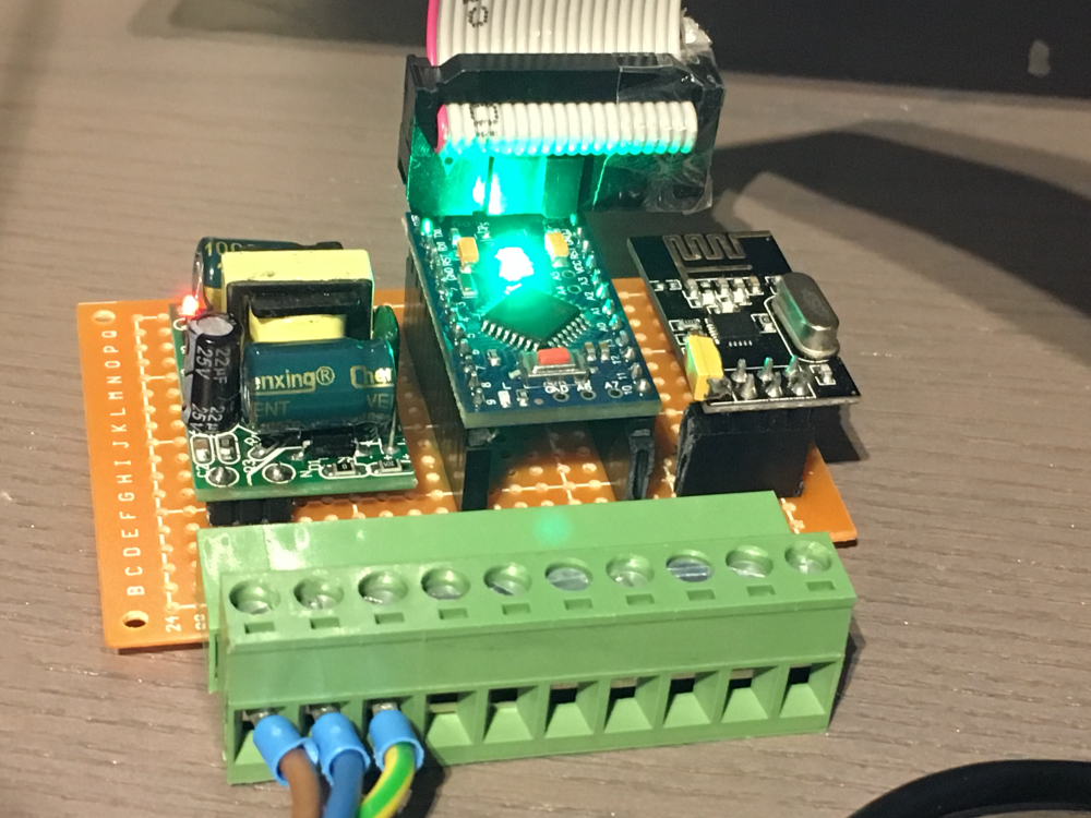
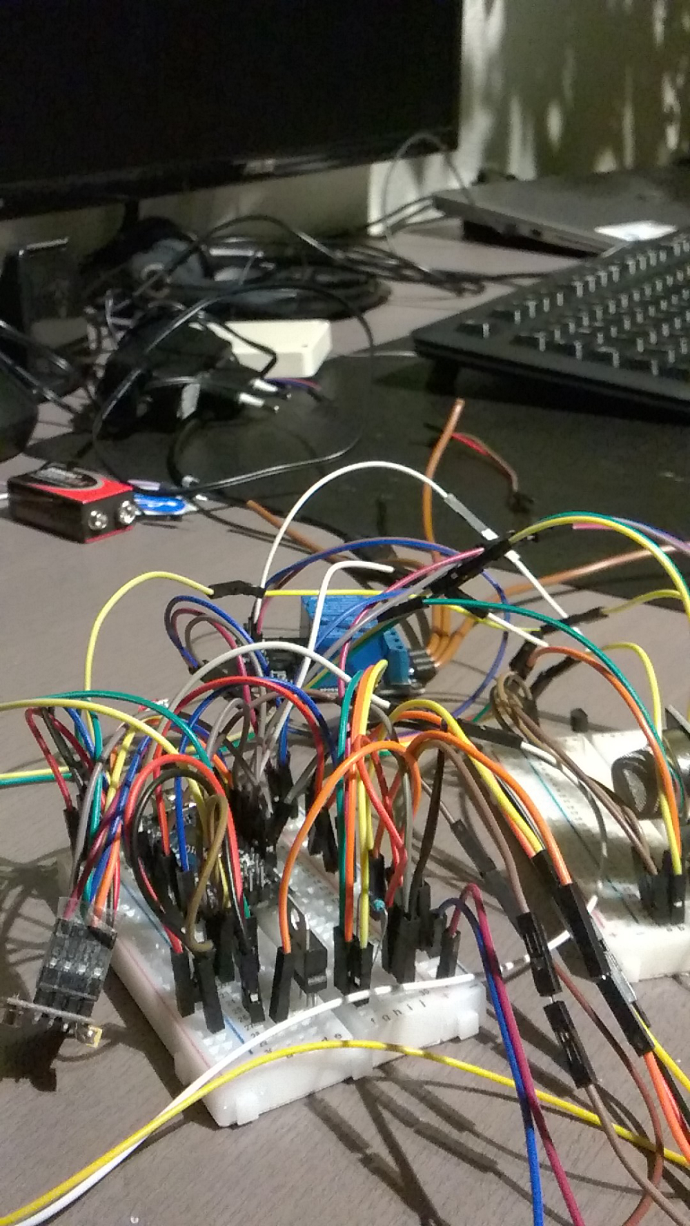
      Soldering components……. Check
      Mechanical work……Check.
      Programming/Reading code Arduino…..No Check.

      Okay a new challenge is born but also this hurdle can be taken. Udemy and my college were my friends. It took me a while to get it all together but the sensor came alive.
      You start with just a simple light on/off switch but… Hmmm….

      If there is enough light you don’t need to turn on the light (Lux Sensor added) ?
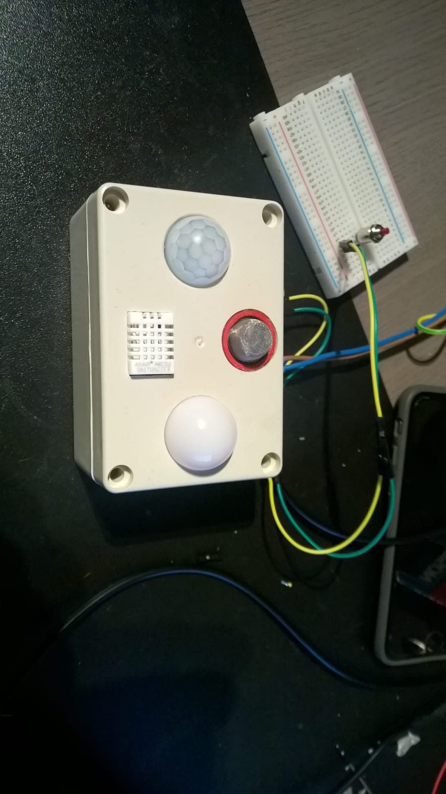
      If there is motion you can turn the light on automatically (Motion sensor added)?
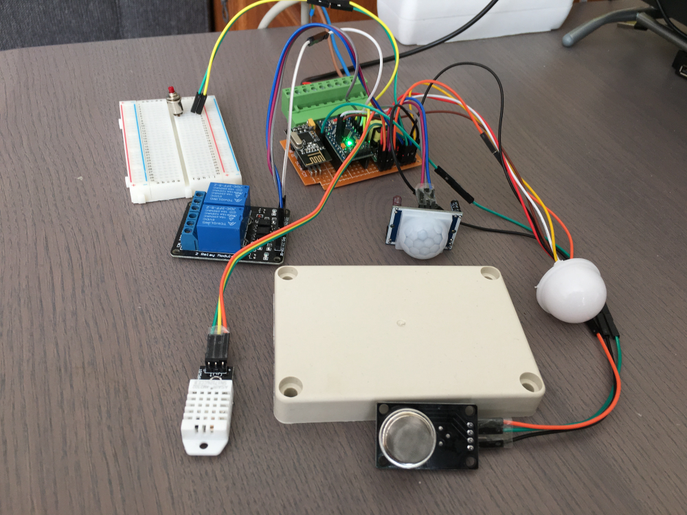
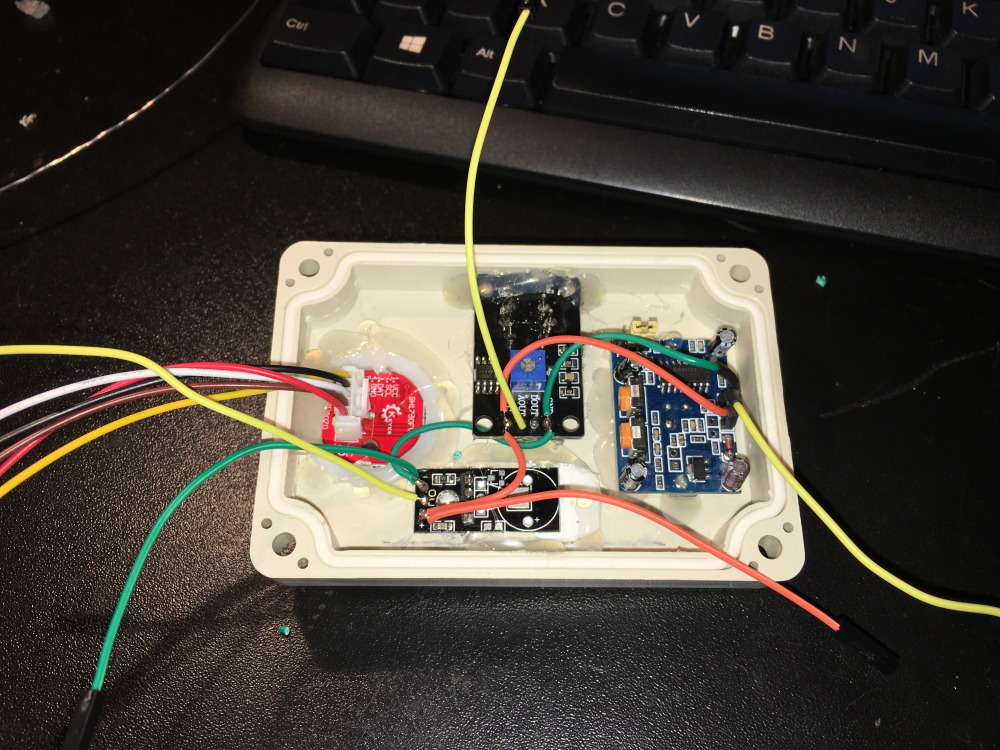
      So let’s also monitor the humidity and temperature in the room (DTH-22 added).
      What about the air in the room smoke, CO and quality? (MQ-2 added).
      It’s all in one box ( DS-18b20 Temperature sensor added).

      And almost forgot to mention the reason why this project began… the light switch.
      It’s now a relay with two coils latched. , the reason for this is it saves current through the coil of the relay.

      The next project is creating a PCB which I have done 30 years ago. Found a program called Eagle and the result is in tje pictures below.0_1522691770955_MyPCB_MyMultiSensor.jpg

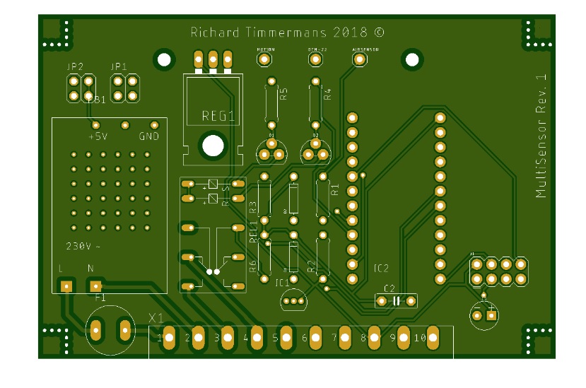
      To all.... Have fun building your sensor. i know I did.

      Best regard

      Richard.

      Please comment on improvements. 0_1522691381092_IMG_0652.JPG
      0_1522691405483_996849b8-d226-4f6e-8e35-78d1abb004aa.JPG
      0_1522691426262_IMG_0608.JPG
      0_1522691454172_IMG_0661.JPG
      0_1522691468334_WP_20180321_22_11_27_Rich.jpg

      posted in My Project
      DaTim69
      DaTim69
    • RE: 💬 Power Meter Pulse Sensor

      I created this kWh sensor with the TCRT5000 IR Barrier Line Track Sensor.
      My powermeter is a ferarrismeter with 375 rotations per kWh.
      I also had the problem with spikes in the power usage. But after long...too long investigation I solved the problem.
      At my config it was a double issue.

      Issue 1.
      The problem is the pulse width of the rotation.
      The pulse are at night ( low power) much wider that during the day when more power is consumed. At night the spikes in power usage where huge.

      Issue 2.
      Switching on/off the halogen light causes spikes and related to also strange power measurement.

      Solution:
      I added a second arduino mini pro as a pulse regulator between the TCRT5000 and the power meter arduino.
      this arduino triggers on Rising and will always give a 100ms puls. Als debounce is handled (spikes).
      I don't upload the sketch here, I'm a beginning programmer on arduino. It's made on " trail and error" but it functions as it supposed to do.
      If someone wants a copy feel free to contact mee

      posted in Announcements
      DaTim69
      DaTim69