Thank you for the inspiration sincze! I have made my own iteration based on yours for a Brink renovent 300/400 excellent, ESP8266 and home assistant integration. I will post some snippets, mainly because the color coding was somewhat confusing as many wires have different colors than yours.
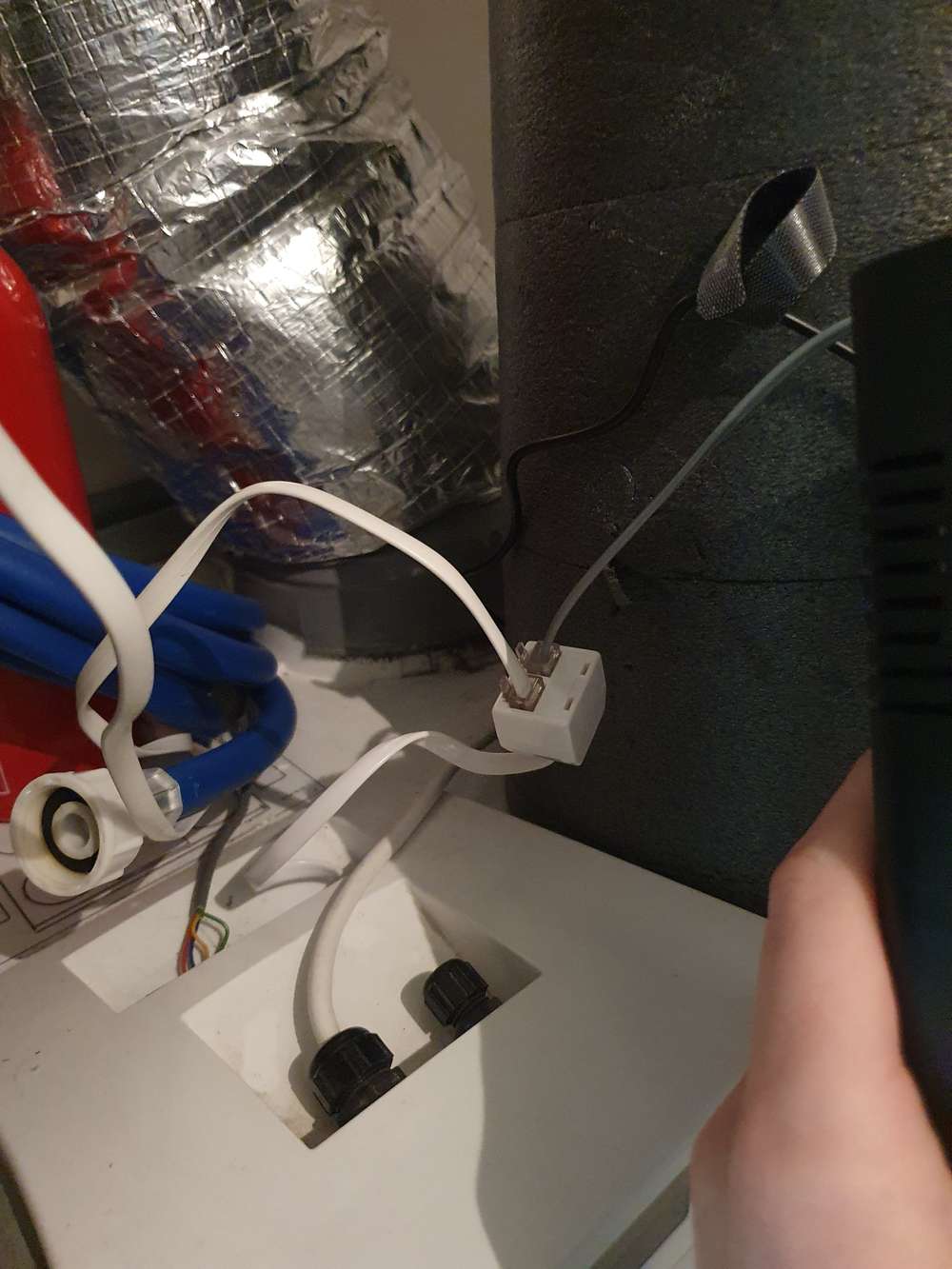
I used an RJ12 cable and splitter so that my Brink RF transmitter can stay in place and also copied your idea for the filter indicator.

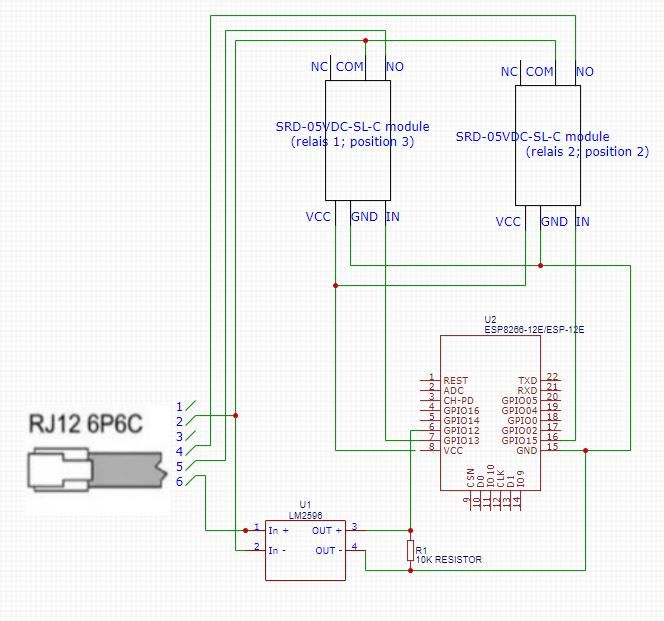
The RJ12 pinout is as follows (see p. 28 in the installation guide)
Pin 1: 24V (not connected but could theoretically be used as a power supply)
Pin 2: GND
Pin 3: Position 0/sleep mode (not connected in my case
Pin 4: position 2, to enable connect to ground with relay (~13 V to ground)
Pin 5: position 3, to enable connect to ground with relay (~13V to ground)
Pin 6: Filter indicator (gives off 24V to GND when filter needs cleaning/replacement).
Note that:
- the Brink defaults to position 1 and that it is capable of handling two inputs simultaneously as it is made to handle multiple switches (e.g. 2 RF modules). Nevertheless I 'interlocked' both relays in ESPhome.
- I'm not yet sure what's current is drawn if the filter indicator is on. Might need a heat sink for the voltage regulator.
- I connected a 5V microUSB power supply to my ESP8266 in order to supply the necessary 5V to the relays.
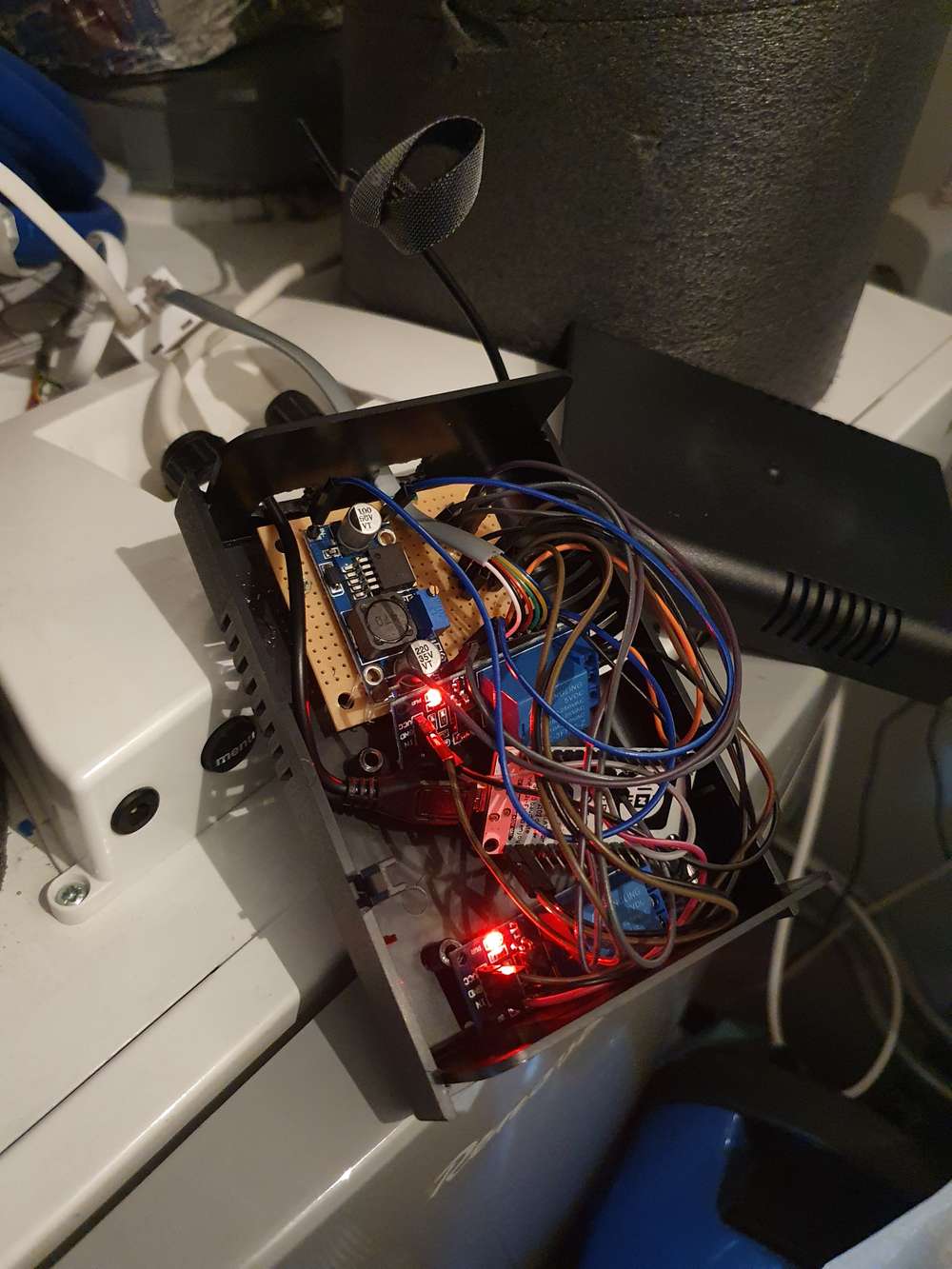
My wiring:
In ESPhome I configured it as follows:
switch:
  - platform: gpio
    name: "position 3"
    id: relay1
    pin: D7
    interlock: [relay2]
  - platform: gpio
    name: "position 2"
    id: relay2
    pin: D8
    interlock: [relay1]
  - platform: template
    name: "position1"
    id: "position1"
    turn_on_action:
     - switch.turn_off: relay1
     - switch.turn_off: relay2
     - switch.turn_off: position1

binary_sensor:
  - platform: gpio
    device_class: problem
    pin: D6
    name: "Brink renovent filter indicator"
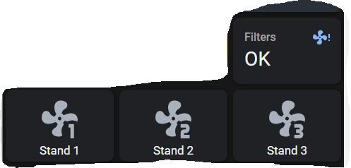
In home assistant I used this this blueprint to automatically switch the fan to position3 based on the bathroom humidity.
Some (messy) pictures are included of the device and HA lovelace view.