@keldandorin Yes. See the response by @gohan. I used a "adapter" with a voltage regulator on it etc. Though, at the moment I don't recall the model number.
M
marlin
@marlin
Posts
-
💬 Building a Raspberry Pi Gateway -
💬 Building a Raspberry Pi Gateway@gohan Thanks! You were correct. I also had one of those "adapters" lying around which I did not need for my Arduino nodes with MySensors, though it came into use for the Rp3.
-
💬 Building a Raspberry Pi Gateway@marceloaqno I am trying to get a Pi 3 working with MySensors 2.1.1 and nrf24l01 and using your updated wire guide, but all I get as output is the following:
mysgw: Starting gateway...
mysgw: Protocol version - 2.1.1
mysgw: MCO:BGN:INIT GW,CP=RNNG--Q,VER=2.1.1
mysgw: TSF:LRT:OK
mysgw: TSM:INIT
mysgw: TSF:WUR:MS=0
mysgw: !TSM:INIT:TSP FAIL
mysgw: TSM:FAIL:CNT=1
mysgw: TSM:FAIL:PDT
[The output repeats itself, increasing the CNT every time, while at the same time one of the cores on the Pi 3 is running at full CPU utilization.]By reading earlier comments I assume this is a wiring problem. One possible cause is inconsistency between
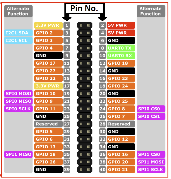
and
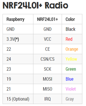
where the first picture indicates that pin 24 and pin 26 should be used, while the second indicates pins 22 and 24 should be used. However, I have tried both options but I still get the same output (I used different nrf24's for the different setups, in case the nrf24 got burned from the first setup).
I have VCC from nrf24 connected to pin 17 on the Pi 3 and GND connect to pin 25.
Any suggestions on what to try next?
[The Pi 3 is running Raspbian with Pixel. For information, I already have a running Arduino with MySensors MQTT GW and a simple node with MySensors and DHT22. From this I know that by nrf24 chips works when being fed with 3.3V.]