💬 Building a Raspberry Pi Gateway


  • @marceloaqno I should have specified, I'm getting the connection errors with the ethernet gateway.


  • Code Contributor

    @pete1450 Could you send the debug log with the connection errors?


  • @marceloaqno After installing broker and gateway fresh, seems to be working. Thanks for your help.


  • @marceloaqno
    Ran as root and made sure I didn't have mysgw already running:

    rm -r MySensors/
    git clone https://github.com/mysensors/MySensors.git --branch master
    cd MySensors/
    ./configure --my-controller-ip-address=192.168.1.136 --my-port=5003 --my-rf24-irq-pin=15
    make
    
    
    root@raspberrypi:~/downloads/MySensors# ./bin/mysgw -d
    mysgw: Starting gateway...
    mysgw: Protocol version - 2.1.1
    mysgw: MCO:BGN:INIT GW,CP=RNNG--Q,VER=2.1.1
    mysgw: TSF:LRT:OK
    mysgw: TSM:INIT
    mysgw: TSF:WUR:MS=0
    mysgw: TSM:INIT:TSP OK
    mysgw: TSM:INIT:GW MODE
    mysgw: TSM:READY:ID=0,PAR=0,DIS=0
    mysgw: MCO:REG:NOT NEEDED
    mysgw: connect: Connection refused
    mysgw: failed to connect
    mysgw: Eth: connect


  • every few days mysgw randomly dies 😞

    Jan 19 06:40:01 pi mysgw[17960]: TSF:MSG:READ,5-5-0,s=255,c=3,t=21,pt=1,l=1,sg=0:0
    Jan 19 06:40:01 pi mysgw[17960]: Sending message on topic: mysensors/out/1/5/255/3/0/21
    Jan 19 06:40:01 pi mysgw[17960]: TSF:MSG:READ,0-5-255,s=255,c=3,t=20,pt=0,l=0,sg=0:
    Jan 19 06:40:01 pi mysgw[17960]: TSF:MSG:BC
    Jan 19 06:40:01 pi systemd[1]: mysgw.service: main process exited, code=killed, status=11/SEGV
    Jan 19 06:40:01 pi systemd[1]: Unit mysgw.service entered failed state.


  • Code Contributor

    @pete1450 If you use the --my-controller-ip-address= option, the gateway will act as a client and attempt to conect to the supplied ip and port. If you want the gateway to open port 5003, omit this option.


  • @marceloaqno what is the correct configure option to make this gatway connect to an ethernet gateway and let a serial-only-controller connect to it. I suppose to use the pty option, but didn't got this working. As said above, socat and nodered are no option.


  • @marceloaqno Well that fixed the connection issue. Now I'm just back to square one where pressing start doesn't do anything. Why do I not need to specify my controllers ip? That is the ip for my veralite. Whats the use case for that option.


  • Code Contributor

    @b0rmann Could you provide the following information?

    • Your RPi model and which linux distribution you are using.
    • gcc version
    • The version and options you used to build the gateway (./configure --option)
    • The number of nodes on your network that sends messages to the gateway.
    • The broker you are using for MQTT and its version

  • Code Contributor

    @Anduril Sorry, the gateway does not support what you're trying to do.


  • Code Contributor

    @pete1450
    I can't help you with this, I've never used the Vera controller. You need to search in the Vera settings where you set this option. If Vera supports being a server and opening a port for the gateway to connect, then you use the --my-controller-ip-address option.


  • Does anyone know if the Raspberry implementation have a UserPassword option for ./configure MQTT


  • @Michael-Curtis Nevermind, I fixed it.... you ned to add :

    --my-mqtt-password=<PASS>   MQTT password
    --my-mqtt-client-id=<ID>    MQTT client id.
    

    Under "cat"

    And for the actual options under "opt do"

    --my-mqtt-user=*)
        CPPFLAGS="-DMY_MQTT_USER=\\\"${optarg}\\\" $CPPFLAGS"
        ;;
    --my-mqtt-password=*)
        CPPFLAGS="-DMY_MQTT_PASSWORD=\\\"${optarg}\\\" $CPPFLAGS"
        ;;
    

    then just add those option flags to the ./configure and run make


  • what means "5VReg -> 3.3V" in raspberry? can connect directly to 3.3V or if requied connecto to 5V with regulator to obtain 3.3v?


  • Hi 🙂 Does anybody know how to use MY_SIGNING_NODE_WHITELISTING in gateway raspbery pi? Where I must create/edit white list with my nodes?


  • first sorry about the basics question but I think many people have the same questions and can't find the answers:
    After connecting the radio (including IRQ on 15pin) and the info LEDs to the GPIO, how to config it?

    1. Do I need to configure all the info on the same command, or can I send the command "./configure --" many times for different configs?
    2. Do I need to configure it as a MQTT gateway?
    3. Where did the 127.0.0.1 IP come from?
    4. Does MQTT use internet connection?
    5. Why do you talk about Serial Gateway here, once we have a specific type for it? this type is about using GPIO only, isn't it? That is confusing!!!


  • trying to config on a Home Assistant Rpi.
    Sorry again for the newbie questions...!!!


  • Hi,
    Can I use pin 18 (GPIO 24) on my RPi3 for IRQ usage? Should I?
    If I compile with --my-rf24-irq-pin=18, no date is received when the gateway starts.
    I Cannot use pin 15 because that pin is covered by my Z-wave.me board.
    Regards,
    Erik


  • Code Contributor

    @Roberto-Mo-Ca If you are using the nrf24 PA/LNA version you need to use a 5V->3.3V regulator otherwise you can connect to the 3.3v pin.


  • Code Contributor

    @macvictor For the MY_SIGNING_NODE_WHITELISTING, you can uncomment and edit it in MyConfig.h or add it to the examples/mysgw.cpp.


  • Code Contributor

    @OliverDog

    You execute ./configure once with all your options to set your gateway.

    You need to decide what type of gateway you want to build: ethernet, serial or mqtt:
    https://www.mysensors.org/build/select_gateway

    Take a look at the link and let me know if you still have any questions.


  • thaks @marceloaqno but I was wondering there was a new type of gateway named Raspberry Gateway, were we could connect the radio directly on the GPIO and config it locally, without internet, because of that I also would like to know if MQTT uses internet connection.
    I actually use a serial gateway connected to Pi USG and it works without internet...
    I just want to have only one device...
    Thanks


  • Code Contributor

    @OliverDog You can configure the RPi to be any of the 3 types: ethernet, serial or mqtt, with the nrf24 attached to it.


  • @marceloaqno WOWWW
    now I understood... but I think this is not clear on the build steps...
    I choose a Serial Gateway, but on that lines, they say:
    "If for some reason you can't use the GPIO pins of the Raspberry Pi, you could connect the radio to a arduino with the GatewaySerial sketch and feed the pi through a serial port:"

    So I assumed the serial gateway is the same I already use...
    So, where do I get directions to config a serial gateway with the radio attached to the GPIO?

    Thanks


  • Code Contributor

    @OliverDog Which controller are you using(or are planning to use)?


  • Code Contributor

    @Erik-Tamminga Some pins may have some restrictions, I couldn't find any good info about that. Try using another pin (GPIO 25).


  • @marceloaqno I already use Home Assistant with a Serial Gateway connected on pi USB.


  • Code Contributor

    @OliverDog Home Assistant supports ethernet gateways, I recommend you go with that.

    ./configure --my-gateway=ethernet --my-transport=nrf24
    

    (The default settings is to use ethernet and nrf24, so you could omit them)

    and add to it any of your custom options.


  • I have a question regarding the --my-serial-groupname option: since I start the gateway under an user account with sudo, the gateway device ([EDIT] symlink) will be created with ownership root:root. Shouldn't it be created with root:dialout (as I chose dialout as group in my case)?

    [DELETED]


  • Code Contributor

    @Madhias /dev/pts/2 it's the one who holds the specified group ownership


  • @marceloaqno OK, many thanks for that hint!

    I was wrong from the beginning on, since I thought my configuration for the gateway was correct because of --my-serial-groupname=dialout - but that was not compiled. I edited now the mysgw.cpp manually (there was tty instead of dialout; and of course there was all the time the warning when compiling...). Now it works! Without chmod, or chowning anything later!


  • @marceloaqno Thank's for you help. I have other question.. general I try configure my gateway to work with security & signing, but they doesn't work. Where is problem? On the bottom i send point what it do it:

    Gateway:

    1. ./configure --my-gateway=mqtt --my-controller-ip-address=127.0.0.1 --my-mqtt-publish-topic-prefix=mysensors-out --my-mqtt-subscribe-topic-prefix=mysensors-in --my-mqtt-client-id=mygateway1 --my-mqtt-password=PASS --my-mqtt-user=USER --my-rf24-encryption-enabled --my-signing=software --my-signing-request-signatures --my-signing-request-gw-signatures-from-all
    2. make
    3. sudo make install
    4. sudo systemctl enable mysgw.service
    5. sudo systemctl start mysgw.service
    6. sudo mysgw --gen-soft-hmac-key
    7. sudo mysgw --set-soft-hmac-key=02417628BC1573CC380...
    8. sudo mysgw --gen-soft-serial-key
    9. sudo mysgw --set-soft-serial-key=00762CD152B868F7EB
    10. sudo mysgw --gen-aes-key
    11. sudo mysgw --set-aes-key= A790AD78B2D8B4DBBB5B2C4B9DD6DAF3

    Node:

    1. Load script SecurityPersonalizer.ino
    2. Uncomment and send sketch to arduino
    #define USE_SOFT_SIGNING
    #define STORE_SOFT_KEY
    #define USER_SOFT_KEY
    #define STORE_SOFT_SERIAL
    #define STORE_AES_KEY
    #define USER_AES_KEY
    
    #define MY_SOFT_HMAC_KEY 0X2,0X41,0X76,0X28,0XBC,0X15,0X73,0XCC,0X38...
    #define MY_AES_KEY 0XA7,0X90,0XAD,0X78,0XB2,0XD8...
    
    1. Read all value from EPROM (test save):
    Personalization sketch for MySensors usage.
    -------------------------------------------
    EEPROM configuration:
    SOFT_HMAC_KEY | 02417628BC1573CC380DE0FADF7C87D7D3C77272A783E6E438786A07C3A8C6CF
    SOFT_SERIAL   | 39BB1370C289643251
    AES_KEY       | A790AD78B2D8B4DBBB5B2C4B9DD6DAF3
    --------------------------------
    Personalization is now complete.
    
    1. Send sample sketch to arduino:
    //!< Enable debug prints to serial monitor
    #define MY_DEBUG
    //!< Enable signing related debug prints to serial monitor
    #define MY_DEBUG_VERBOSE_SIGNING
    // Enable NRF24L01 radio type
    #define MY_RADIO_NRF24
    
    // Select soft signing
    #define MY_SIGNING_SOFT
    
    // Enable lockdown of node if suspicious activity is detected
    //-->> #define MY_NODE_LOCK_FEATURE
    
    // Enable node whitelisting
    //#define MY_SIGNING_NODE_WHITELISTING {{.nodeId = GATEWAY_ADDRESS,.serial = {0x09,0x08,0x07,0x06,0x05,0x04,0x03,0x02,0x01}}}
    
    // Enable this if you want destination node to sign all messages sent to this node.
    #define MY_SIGNING_REQUEST_SIGNATURES
    
    // SETTINGS FOR MY_SIGNING_SOFT
    #define MY_SIGNING_SOFT_RANDOMSEED_PIN 7 //!< Unconnected analog pin for random seed
    
    // Add repeater function to this sensor
    #define MY_REPEATER_FEATURE
    
    
    #include <SPI.h>
    #include <MySensors.h>
    #include <Bounce2.h>
    
    #define RELAY_PIN  4    // Arduino Digital I/O pin number for relay 
    #define BUTTON_PIN  3   // Arduino Digital I/O pin number for button 
    #define CHILD_ID 1      // Id of the sensor child
    #define RELAY_ON 1
    #define RELAY_OFF 0
    
    Bounce debouncer = Bounce();
    int oldValue = 0;
    bool state;
    
    MyMessage msg(CHILD_ID, V_LIGHT);
    
    void setup()
    {
      // Setup the button
      pinMode(BUTTON_PIN, INPUT);
      // Activate internal pull-up
      digitalWrite(BUTTON_PIN, HIGH);
    
      // After setting up the button, setup debouncer
      debouncer.attach(BUTTON_PIN);
      debouncer.interval(5);
    
      // Make sure relays are off when starting up
      digitalWrite(RELAY_PIN, RELAY_OFF);
      // Then set relay pins in output mode
      pinMode(RELAY_PIN, OUTPUT);
    
      // Set relay to last known state (using eeprom storage)
      state = loadState(CHILD_ID);
      digitalWrite(RELAY_PIN, state ? RELAY_ON : RELAY_OFF);
    }
    
    void presentation()  {
      // Send the sketch version information to the gateway and Controller
      sendSketchInfo("Relay & Button", "1.0");
      
      // Register all sensors to gw (they will be created as child devices)
      present(CHILD_ID, S_LIGHT, "Switch Secure Sensor", false);
    }
    
    /*
       Example on how to asynchronously check for new messages from gw
    */
    void loop()
    {
      debouncer.update();
      // Get the update value
      int value = debouncer.read();
    //  if (value != oldValue && value == 0) {
        send(msg.set(state ? false : true), true); // Send new state and request ack back
    //  }
    //  oldValue = value;
      delay(5000);
    }
    
    void receive(const MyMessage &message) {
      // We only expect one type of message from controller. But we better check anyway.
      if (message.isAck()) {
        Serial.println("This is an ack from gateway");
      }
    
      if (message.type == V_LIGHT) {
        // Change relay state
        state = message.getBool();
        digitalWrite(RELAY_PIN, state ? RELAY_ON : RELAY_OFF);
        // Store state in eeprom
        // saveState(CHILD_ID, state);
    
        // Write some debug info
        Serial.print("Incoming change for sensor:");
        Serial.print(message.sensor);
        Serial.print(", New status: ");
        Serial.println(message.getBool());
      }
    }
    

    And finally in Arduino Serial Monitor I see:

    0 MCO:BGN:INIT REPEATER,CP=RNNRAS-,VER=2.1.1
    4 TSM:INIT
    5 TSF:WUR:MS=0
    11 TSM:INIT:TSP OK
    13 TSF:SID:OK,ID=105
    15 TSM:FPAR
    16 Will not sign message for destination 255 as it does not require it
    58 TSF:MSG:SEND,105-105-255-255,s=255,c=3,t=7,pt=0,l=0,sg=0,ft=0,st=OK:
    2065 !TSM:FPAR:NO REPLY
    2067 TSM:FPAR
    2068 Will not sign message for destination 255 as it does not require it
    2110 TSF:MSG:SEND,105-105-255-255,s=255,c=3,t=7,pt=0,l=0,sg=0,ft=0,st=OK:
    4117 !TSM:FPAR:NO REPLY
    4119 TSM:FPAR
    4120 Will not sign message for destination 255 as it does not require it
    4162 TSF:MSG:SEND,105-105-255-255,s=255,c=3,t=7,pt=0,l=0,sg=0,ft=0,st=OK:
    6169 !TSM:FPAR:NO REPLY
    6171 TSM:FPAR
    6172 Will not sign message for destination 255 as it does not require it
    6214 TSF:MSG:SEND,105-105-255-255,s=255,c=3,t=7,pt=0,l=0,sg=0,ft=0,st=OK:
    8221 !TSM:FPAR:FAIL
    8222 TSM:FAIL:CNT=1
    8224 TSM:FAIL:PDT
    

    and in gateway i see:

    sudo mysgw -d
    mysgw: Starting gateway...
    mysgw: Protocol version - 2.1.1
    mysgw: MCO:BGN:INIT GW,CP=RNNG-S-,VER=2.1.1
    mysgw: TSF:LRT:OK
    mysgw: TSM:INIT
    mysgw: TSF:WUR:MS=0
    mysgw: TSM:INIT:TSP OK
    mysgw: TSM:INIT:GW MODE
    mysgw: TSM:READY:ID=0,PAR=0,DIS=0
    mysgw: MCO:REG:NOT NEEDED
    mysgw: MCO:BGN:STP
    mysgw: MCO:BGN:INIT OK,TSP=1
    mysgw: Attempting MQTT connection...
    mysgw: connected to 127.0.0.1
    mysgw: MQTT connected
    mysgw: Sending message on topic: mysensors-out/0/255/0/0/18
    mysgw: TSF:MSG:READ,171-107-54,s=221,c=2,t=131,pt=4,l=25,sg=0:-1418183441
    mysgw: !TSF:MSG:PVER,3=2
    mysgw: TSF:MSG:READ,135-23-172,s=20,c=3,t=200,pt=7,l=25,sg=0:-0.00000178
    mysgw: !TSF:MSG:PVER,1=2
    mysgw: TSF:MSG:READ,34-66-89,s=168,c=1,t=9,pt=1,l=25,sg=0:56
    mysgw: !TSF:MSG:PVER,1=2
    mysgw: TSF:MSG:READ,223-46-240,s=112,c=5,t=192,pt=5,l=11,sg=1:1407647670
    mysgw: TSF:MSG:REL MSG
    mysgw: !TSF:RTE:240 UNKNOWN
    mysgw: !TSF:MSG:SEND,223-0-240-240,s=112,c=5,t=192,pt=5,l=11,sg=1,ft=0,st=NACK:1407647670
    mysgw: TSF:MSG:READ,183-139-129,s=37,c=6,t=155,pt=1,l=21,sg=0:48
    mysgw: !TSF:MSG:PVER,0=2
    mysgw: TSF:MSG:READ,139-214-233,s=61,c=3,t=193,pt=7,l=0,sg=1:0.00000000
    mysgw: TSF:MSG:REL MSG
    mysgw: !TSF:RTE:233 UNKNOWN
    mysgw: !TSF:MSG:SEND,139-0-233-233,s=61,c=3,t=193,pt=7,l=0,sg=1,ft=0,st=NACK:0.00000000
    mysgw: TSF:MSG:READ,83-33-7,s=179,c=2,t=27,pt=4,l=25,sg=1:-2057270722
    mysgw: !TSF:MSG:PVER,3=2
    mysgw: TSF:MSG:READ,110-148-67,s=113,c=0,t=158,pt=1,l=9,sg=1:251
    mysgw: !TSF:MSG:PVER,1=2
    mysgw: TSF:MSG:READ,75-209-102,s=204,c=7,t=25,pt=1,l=11,sg=1:52
    mysgw: !TSF:MSG:PVER,0=2
    mysgw: TSF:MSG:READ,184-209-235,s=58,c=1,t=140,pt=6,l=23,sg=1:1DC404A5401119FACF0000000000000000000000000000
    mysgw: !TSF:MSG:PVER,3=2
    mysgw: TSF:MSG:READ,172-203-51,s=140,c=2,t=173,pt=0,l=1,sg=1:?
    mysgw: TSF:MSG:REL MSG
    mysgw: !TSF:RTE:51 UNKNOWN
    mysgw: !TSF:MSG:SEND,172-0-51-51,s=140,c=2,t=173,pt=0,l=1,sg=1,ft=0,st=NACK:?
    

    Where is problem?


  • Code Contributor

    @macvictor Did you also enable encryption on your node? (#define MY_RF24_ENABLE_ENCRYPTION)


  • @marceloaqno Thanks for help 👍 This was my problem 😀


  • Mod

    how do I set user and password to access the mqtt broker? I tried do add --my-mqtt-password=PASS --my-mqtt-user=USER other parameters but they get ignored


  • @gohan edit configure file and add this code:

    --my-mqtt-user=*)
        CPPFLAGS="-DMY_MQTT_USER=\\\"${optarg}\\\" $CPPFLAGS"
        ;;
    --my-mqtt-password=*)
        CPPFLAGS="-DMY_MQTT_PASSWORD=\\\"${optarg}\\\" $CPPFLAGS"
        ;;
    

    after this code:

    --my-signing-request-gw-signatures-from-all*)
            signing_request_signatures=true
            CPPFLAGS="-DMY_SIGNING_GW_REQUEST_SIGNATURES_FROM_ALL $CPPFLAGS"
            ;;
    

    this is about 408 number line and use flag --my-mqtt-password and --my-mqtt-client-id when you run configure, thats all. 😃


  • Admin

    @macvictor It would be great if you would submit this as a GitHub Pull Request. If you aren't comfortable with that, then I would encourage you to at least open a MySensors issue to add these RPI configuration options.


  • When using RPI as a GW for MySensors, the CPU load increases from 18% to around 80 %. I am using a RPI II model B. I'd love the have the GW running on the Raspberry, and avoid a USB connected Arduino.

    Does somebody else experience the same?


  • @Teknor I use RPI III as GW and all node connect with gw used nRF24L01. My CPU now usage 5-10%, but I installed "Home Assistance" + homebridge + some plugins.


  • @macvictor Thanks. My RPI 2 is running Domoticz, RFXcom GW and 2x 3MP cameras with motion detection using Motioneye. Might be something wrong with my MySensors GW setup...


  • @Teknor I tend to agree something is wrong, but I think it really on depends how many nodes and how often you're sending data.
    rpi3 + GPIO nrf24l01 + openhab2 + 8 nodes + packet received, on average 1 / 5s :

    top - 06:29:37 up 2 days, 22:33,  2 users,  load average: 0.26, 0.24, 0.19
    KiB Mem:    947732 total,   903420 used,    44312 free,   175364 buffers
    KiB Swap:   102396 total,     4496 used,    97900 free.   391360 cached Mem
    
      PID USER      PR  NI    VIRT    RES    SHR S  %CPU %MEM     TIME+ COMMAND                                                               
      681 root      20   0  208840  56532  23684 S   8.9  6.0 214:23.60 Xorg                                                                  
      527 root      20   0   39448  21532  11264 S   4.3  2.3  69:34.28 vncserver-x11-c                                                       
     1154 pi        20   0   50548  17628  12196 S   3.0  1.9  64:05.96 lxterminal                                                            
    30426 openhab   20   0  441764 197592  14960 S   1.6 20.8 284:18.70 java                                                                  
     2467 root      20   0   20024   2456   2300 S   1.3  0.3  62:55.17 mysgw                                                                 
    25634 root      20   0       0      0      0 S   1.0  0.0   0:00.21 kworker/u8:0                                                          
      688 root      20   0   13720   9432   8828 S   0.7  1.0   2:04.96 vncagent                                                              
    25855 pi        20   0    5232   2584   2140 R   0.7  0.3   0:00.49 top                                                                   
        7 root      20   0       0      0      0 S   0.3  0.0   9:15.35 rcu_sched                                                             
       78 root     -51   0       0      0      0 S   0.3  0.0   5:16.50 irq/92-mmc1                                                           
      967 pi        20   0   95656  17716  12028 S   0.3  1.9   6:41.87 lxpanel                                                               
        1 root      20   0   24620   4688   2716 S   0.0  0.5   0:13.08 systemd                                                               
        2 root      20   0       0      0      0 S   0.0  0.0   0:00.27 kthreadd                                                              
    

  • Mod

    @macvictor
    That worked, thanks. But to configure channel, power, AES key, and so on, do you think it is better to use command line like you posted above or customize myconfig.h?


  • Code Contributor

    @gohan You can also set mqtt username and password in examples_linux/mysgw.cpp


  • Mod

    @marceloaqno
    I'm trying to understand where is the best place to avoid file gets overwritten in case of upgrades


  • Code Contributor

    @gohan There is a open github pull request very similar to what @macvictor proposed, but for now I recommend using the examples_linux/mysgw.cpp file.


  • Mod

    @marceloaqno
    Ok I can you that file, but where is the best place to set Power Level and channel ?


  • Code Contributor

    @gohan There isn't exactly the best place to set things, it really depends on your preferences.


  • Mod

    I just copied the myconfig file from the arduino and set the rest from the command line and from debug it looks like it's working, the problem is now to get domoticz talk to the mqtt.


  • Mod

    After updating domoticz to beta version I finally have the MQTT working with controller and I can see the sensor node seding in data: my question now is how to I debug the gateway if it is running as a service on the RPI without messing things up?


  • @marceloaqno I am trying to get a Pi 3 working with MySensors 2.1.1 and nrf24l01 and using your updated wire guide, but all I get as output is the following:
    mysgw: Starting gateway...
    mysgw: Protocol version - 2.1.1
    mysgw: MCO:BGN:INIT GW,CP=RNNG--Q,VER=2.1.1
    mysgw: TSF:LRT:OK
    mysgw: TSM:INIT
    mysgw: TSF:WUR:MS=0
    mysgw: !TSM:INIT:TSP FAIL
    mysgw: TSM:FAIL:CNT=1
    mysgw: TSM:FAIL:PDT
    [The output repeats itself, increasing the CNT every time, while at the same time one of the cores on the Pi 3 is running at full CPU utilization.]

    By reading earlier comments I assume this is a wiring problem. One possible cause is inconsistency between
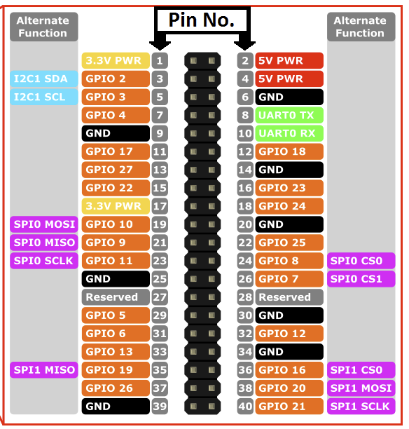
    0_1488723559852_upload-e3165792-1f42-4663-8e68-efd96bd275f8

    and

    0_1488723638471_upload-d7048ef8-8a33-4214-9935-0356cf9291c2

    where the first picture indicates that pin 24 and pin 26 should be used, while the second indicates pins 22 and 24 should be used. However, I have tried both options but I still get the same output (I used different nrf24's for the different setups, in case the nrf24 got burned from the first setup).

    I have VCC from nrf24 connected to pin 17 on the Pi 3 and GND connect to pin 25.

    Any suggestions on what to try next?
    [The Pi 3 is running Raspbian with Pixel. For information, I already have a running Arduino with MySensors MQTT GW and a simple node with MySensors and DHT22. From this I know that by nrf24 chips works when being fed with 3.3V.]


  • Mod

    I have connected my nrf24 like the secon table you posted and it is working but I am using an "adapter" for nrf24 with a socket and has voltage regulator + capacitors, so if you don't have any cap on the radio module, I'd suggest you put one on (try from a 4.7 uF up to 47 and see if anything changes)


  • @gohan Thanks! You were correct. I also had one of those "adapters" lying around which I did not need for my Arduino nodes with MySensors, though it came into use for the Rp3.


  • @gohan said in 💬 Building a Raspberry Pi Gateway:

    After updating domoticz to beta version I finally have the MQTT working with controller and I can see the sensor node seding in data: my question now is how to I debug the gateway if it is running as a service on the RPI without messing things up?

    I have my gateway on a headless pi 3, no monitor, GUI or keyboard. (I don't care for the nest of wires connection to the pi.) I also use MQTT which is very reliable.

    An easy way to see the full MQTT traffic is to not start (or kill if it starts on boot) the MQTT server in the background, and start it in the console you can monitor. This won't impact Domotics one bit. In my case I do this by invoking "mosquitto -d" in the terminal

    A simple way to monitor MQTT once its up and running is to look at the Domotics Log on the Setup menu.

    Another way to watch it is to, in a terminal window such as running ssh from your computer, use MQTT "sub" in your terminal to see the MQTT traffic both ways to and from Domotics. If this isn't familiar, you need to learn it, (read the MQTT docs) and it's quite simple. Example might be "ssh pi@rpi.local" or "ssh <IP address>" from a computer on the local network, assuming the user is named pi and the pi is named "rpi"

    Your MQTT topic must match what is in the sensor node sketch, the gateway sketch, and the domotics MQTT config. In my case I use "mosquitto_sub -d -v -t domoticz" and everything starts showing in real time in the terminal window.

    MQTT is a bit more fiddly to set up but it's nice that different environments can push sensor data into the same MQTT server, in my case MySensors and ESP Easy.

    Tim


  • @marlin said in 💬 Building a Raspberry Pi Gateway:

    where the first picture indicates that pin 24 and pin 26 should be used, while the second indicates pins 22 and 24 should be used.

    Be careful because the wiring page shows two pinout diagrams, one for the Pi 1, another for the Pi 2&3, but which is which is not inside the graphic itself. Please don't ask how I know. 😉

    Tim


  • Mod

    @Grubstake
    I am using mqtt fx from pc and subscribing to topic # so I get the full traffic of what is going on, but I haven't had time lately to compare if you get same log details as the myscontroller connected to ethernet gateway or starting the gateway on rpi with debug flag


  • @marlin Got the same issue, Did you solve yours and if so how?


  • @keldandorin Yes. See the response by @gohan. I used a "adapter" with a voltage regulator on it etc. Though, at the moment I don't recall the model number.


  • Mod

    @keldandorin just add a capacitor between vcc and gnd on the radio module as I suggested above.


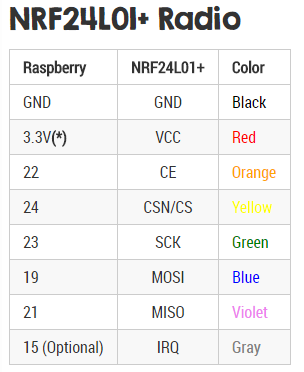
  • I am trying to connect NRF24L01+ and Raspberry Pi 2 (Model B+). I am confuse about pin 22/24 too. In the diagram it shows "SPI0 CS0" and "SPI0 CS1" but these two pins aren't exist in NRF24L01+. How should I connect the pin? I connect Pi2 pin 24 to CS and Pi2 pin 26 to CE (Not sure it is correct)? Here is the message from mysgw:

    [root@alarmpi bin]# ./mysgw -d
    mysgw: Starting gateway...
    mysgw: Protocol version - 2.1.1
    mysgw: MCO:BGN:INIT GW,CP=RNNG---,VER=2.1.1
    mysgw: TSM:INIT
    mysgw: TSF:WUR:MS=0
    mysgw: !TSM:INIT:TSP FAIL
    mysgw: TSM:FAIL:CNT=1
    mysgw: TSM:FAIL:PDT
    mysgw: TSM:FAIL:RE-INIT
    mysgw: TSM:INIT
    mysgw: !TSM:INIT:TSP FAIL
    mysgw: TSM:FAIL:CNT=2
    mysgw: TSM:FAIL:PDT
    mysgw: TSM:FAIL:RE-INIT
    mysgw: TSM:INIT
    mysgw: !TSM:INIT:TSP FAIL
    mysgw: TSM:FAIL:CNT=3
    mysgw: TSM:FAIL:PDT


  • @ccy Look at the chart below "NRF24L01+ Radio". That shows the PIN numbers on the Pi and the pin labels on the radio to interconnect. Pay no attention to the labels on the RPi generic pinout diagram except the PIN numbers. The RPi SPIO labels are not what you are looking for. And be sure to use the chart for the correct RPi model.


  • Mod

    Exactly, I was about to write pretty much the same 😀


  • @gohan I beat you to it! 😃


  • @Grubstake: Thanks. I have tried to follow "NRF24L01+ Radio" pin out connection. I have double / triple check my wiring is correct. But I still get the same fail message in mysgw debug mode:

    [root@alarmpi bin]# ./mysgw -d
    mysgw: Starting gateway...
    mysgw: Protocol version - 2.1.1
    mysgw: MCO:BGN:INIT GW,CP=RNNG---,VER=2.1.1
    mysgw: TSM:INIT
    mysgw: TSF:WUR:MS=0
    mysgw: !TSM:INIT:TSP FAIL
    mysgw: TSM:FAIL:CNT=1
    mysgw: TSM:FAIL:PDT
    mysgw: TSM:FAIL:RE-INIT
    mysgw: TSM:INIT
    mysgw: !TSM:INIT:TSP FAIL
    mysgw: TSM:FAIL:CNT=2
    mysgw: TSM:FAIL:PDT
    mysgw: TSM:FAIL:RE-INIT
    mysgw: TSM:INIT
    mysgw: !TSM:INIT:TSP FAIL
    mysgw: TSM:FAIL:CNT=3
    mysgw: TSM:FAIL:PDT
    mysgw: Received SIGINT
    

    Here is my /boot/config.txt:

    gpu_mem=64
    initramfs initramfs-linux.img followkernel
    dtparam=spi=on
    

    and the spi dev:

    # ls /dev/spidev0.*
    /dev/spidev0.0  /dev/spidev0.1
    

    I am using ArchLinuxARM:

    # uname -a
    Linux alarmpi 4.9.13-3-ARCH #1 SMP Fri Mar 3 18:45:16 MST 2017 armv7l GNU/Linux
    

    I only wiring 7 pins (1-7) on NRF24l01+.

    Raspberry Pi 2 hardware information:

    # cat /proc/cpuinfo
    processor       : 0
    model name      : ARMv7 Processor rev 5 (v7l)
    BogoMIPS        : 38.40
    Features        : half thumb fastmult vfp edsp neon vfpv3 tls vfpv4 idiva idivt vfpd32 lpae evtstrm
    CPU implementer : 0x41
    CPU architecture: 7
    CPU variant     : 0x0
    CPU part        : 0xc07
    CPU revision    : 5
    
    processor       : 1
    model name      : ARMv7 Processor rev 5 (v7l)
    BogoMIPS        : 38.40
    Features        : half thumb fastmult vfp edsp neon vfpv3 tls vfpv4 idiva idivt vfpd32 lpae evtstrm
    CPU implementer : 0x41
    CPU architecture: 7
    CPU variant     : 0x0
    CPU part        : 0xc07
    CPU revision    : 5
    
    processor       : 2
    model name      : ARMv7 Processor rev 5 (v7l)
    BogoMIPS        : 38.40
    Features        : half thumb fastmult vfp edsp neon vfpv3 tls vfpv4 idiva idivt vfpd32 lpae evtstrm
    CPU implementer : 0x41
    CPU architecture: 7
    CPU variant     : 0x0
    CPU part        : 0xc07
    CPU revision    : 5
    
    processor       : 3
    model name      : ARMv7 Processor rev 5 (v7l)
    BogoMIPS        : 38.40
    Features        : half thumb fastmult vfp edsp neon vfpv3 tls vfpv4 idiva idivt vfpd32 lpae evtstrm
    CPU implementer : 0x41
    CPU architecture: 7
    CPU variant     : 0x0
    CPU part        : 0xc07
    CPU revision    : 5
    
    Hardware        : BCM2835
    Revision        : a21041
    Serial          : 00000000475d18a4
    
    # cat /sys/firmware/devicetree/base/model
    Raspberry Pi 2 Model B Rev 1.1
    

    Output from MySensors configure:

    # ./configure
    [SECTION] Detecting target machine.
    ./configure: line 111: warning: command substitution: ignored null byte in input
      [OK] machine detected: SoC=unknown, Type=unknown, CPU=armv7l.
    [SECTION] Checking GPIO Sysfs.
      [OK] /sys/class/gpio/export found
    [SECTION] Detecting SPI driver.
      [OK] SPI driver detected:SPIDEV.
    [SECTION] Detecting init system.
      [OK] init system detected: systemd.
    [SECTION] Saving configuration.
    [SECTION] Cleaning previous builds.
    [OK] Finished.
    

    I finally find out my raspberry pi board isn't detected properly in configure. I change the function detect_machine:

    function detect_machine {
    ...
        case $hardware in
    ...
        BCM2835)
            soc="BCM2835"
            if [[ $machine == "Raspberry"* ]]; then
                local rev=($(detect_rpi_revision))
                if [[ $rev == "a02082" || $rev == "a22082" ]]; then
                    tp="RPi3"
                else
                    tp="Rpi2"
                fi
            fi
            ;;
    ...
    

    make mysgw again, and I get this finally:

    # ./mysgw -d
    mysgw: Starting gateway...
    mysgw: Protocol version - 2.1.1
    mysgw: MCO:BGN:INIT GW,CP=RNNG---,VER=2.1.1
    mysgw: TSF:LRT:OK
    mysgw: TSM:INIT
    mysgw: TSF:WUR:MS=0
    mysgw: TSM:INIT:TSP OK
    mysgw: TSM:INIT:GW MODE
    mysgw: TSM:READY:ID=0,PAR=0,DIS=0
    mysgw: MCO:REG:NOT NEEDED
    mysgw: Listening for connections on 0.0.0.0:5003
    mysgw: MCO:BGN:STP
    mysgw: MCO:BGN:INIT OK,TSP=1


  • I can run mysgw. But what can I use it for? I want to make it control my light with 2.4G RF. But I don't know what to do next. Please advice Thank you.


  • Mod

    @ccy
    You need to provide some more details about your hw and general setup, what have you done so far, log messages, etc.


  • @gohan Sorry for my typo mistake. I can now run mysgw. But what can I use it for? I am trying to control my light with 2.4G RF.


  • Mod

    Do you mean your light has already 2.4G RF or do you need to make a relay node with NRF24 that can switch on and of that light? But this is going a little OT in this thread.


  • @gohan Yes. I want to do that. I am sure my LED controller is 2.4G RF. But I can't detect any signal yet from my nrf24l01+ on raspberry pi. I am not sure what's wrong. Still trying now...


  • Mod

    @ccy
    Being 2.4G RF doesn't mean it is NRF24L01 compatible also without knowing what channel is using will make it even more difficult. So, unless you want to make a Mysensors LED Controller, I think you are out of luck if you want to directly control your existing one with a RPI and the mysensors gateway. Either way this is OT.


  • @gohan Is there a way to know the channel by doing some sort of scan? If the channel is known, what are the setting to fix the channel for mysgw?


  • Hello everyone!

    I'm using a Rasp2 (with the 40 pins GPIO header)

    Has anyone experience with using the NRF module on different pins than default? I'm asking because I wonder if I can connect a GPIO-connected touch TFT (which would use the 2 CE lines for the touch and display interfaces) together with the NRF - by hooking the MISO/MOSI/SCLK to the default pins (and thus sharing them between the TFT and NRF) and defining free pins for the CE and CS lines in the ./configure script when compiling the gateway code...?!

    Or maybe using the SPI1 by first enabling it as laid out in this blog post - but how to proceed from there? (How to tell the gateway code to use SPI1?)


  • Code Contributor

    @Velo17

    ./configure --spi-driver=SPIDEV --spi-spidev-device=/dev/spidev1.0
    

    (replace the /dev/spidev1.0 with the one you enabled in /boot/config.txt)


  • Hello Masters,

    Could you please help me with setting up virtual serial port?

    I can't see the interface created under /dev.
    I'm using the instructions and finish with the setup with the following command:

    pi@raspberrypi:/tmp/MySensors $ ./configure --my-gateway=serial --my-serial-is-pty --my-serial-pty=/dev/ttyMySensorsGateway
    [SECTION] Detecting target machine.
      [OK] machine detected: SoC=BCM2836, Type=Rpi2, CPU=armv7l.
    [SECTION] Detecting SPI driver.
      [OK] SPI driver detected:BCM.
    [SECTION] Detecting init system.
      [OK] init system detected: systemd.
    [SECTION] Saving configuration.
    [SECTION] Cleaning previous builds.
    [OK] Finished.
    
    pi@raspberrypi:/ $ sudo /usr/local/bin/mysgw -d
    mysgw: Starting gateway...
    mysgw: Protocol version - 2.1.1
    mysgw: MCO:BGN:INIT GW,CP=RNNG---,VER=2.1.1
    mysgw: TSF:LRT:OK
    mysgw: TSM:INIT
    mysgw: TSF:WUR:MS=0
    mysgw: TSM:INIT:TSP OK
    mysgw: TSM:INIT:GW MODE
    mysgw: TSM:READY:ID=0,PAR=0,DIS=0
    mysgw: MCO:REG:NOT NEEDED
    mysgw: Listening for connections on 0.0.0.0:5003
    mysgw: MCO:BGN:STP
    mysgw: MCO:BGN:INIT OK,TSP=1


    Everything seems to be OK. However, when I check /dev directory, the interface is not created.

    What could be an issue?
    Thank you in advacne!


  • Mod

    Why don't you compile it as ethernet gateway?


  • @gohan Etherner Gareway is not supported by OpenHab MySensors binding.


  • Mod

    Mqtt? 😀


  • @gohan I'm sorry, MQTT is not supported by OpenHab MySensors binding. Ethernet Gateway is not supported on Raspberry PI.


  • Code Contributor

    @engy OpenHab2 supports mysensors serial and ethernet gateways:
    https://github.com/tobof/openhab2-addons/wiki

    Maybe the build guide may have given you that impression, but ethernet Gateway is supported on Raspberry PI:

    ./configure --my-gateway=ethernet


  • @gohan Solved the problem with radio...Thx


  • Thank you guys for prompt reaction. Indeed, Ethernet GW works flawlessly!


  • Hi
    Is anyone else having this same problem on Rpi3?: Gateway works ok after "sudo make install" with openHAB. With "sudo ./bin/mysgw -d" I can get debug log visible and log works ok.
    But if I run "sudo systemctl enable mysgw.service" after "sudo make install", debug log start showing endlessly "mysgw: accept: Bad file descriptor". So debug log function gets destroyed and it can't be used anymore. I have made several clean installations and every time this same happens.
    Br
    Tommi


  • Code Contributor

    @TommiP What I think is happening is that you are running two instances of the gateway.
    If you need to get the debug logs, first stop the mysgw service:

    sudo systemctl stop mysgw.service


  • @marceloaqno
    Ok, now I understand what happened, thanks.


  • Re: 💬 Building a Raspberry Pi Gateway

    Silly questions, I'm a little bit confuse.
    I have a serial Gateway running with arduino nano + nrf24 and a raspberry pi with domoticz on board. The link between domoticz & Gateway is done via USB <=> serial port (/dev/ttyUSB0). This setup runs like a charm.

    Now, I would like to access to my Gateway via the network because I would like to use "Over The Air " functionnality with MYSController.

    Can I install MySensors Gateway on the raspberry and keep the arduino + nrf24 connected via usb ?? For the moment, I can not use GPIO port.

    If for some reason you can't use the GPIO pins of the Raspberry Pi, you could connect the radio to a arduino with the GatewaySerial sketch and feed the pi through a serial port:

    ./configure --my-gateway=serial --my-serial-port=/dev/ttyUSB0 --my-serial-baudrate=115200
    

    [SECTION] Detecting target machine.
    [OK] machine detected: SoC=BCM2836, Type=RPi3, CPU=armv7l.
    [SECTION] Detecting SPI driver.
    [OK] SPI driver detected:BCM.
    [SECTION] Detecting init system.
    [OK] init system detected: systemd.
    [SECTION] Saving configuration.
    [SECTION] Cleaning previous builds.
    [OK] Finished.

    make
    
    ./bin/mysgw -d
    

    mysgw: Starting gateway...
    mysgw: Protocol version - 2.1.1
    mysgw: MCO:BGN:INIT GW,CP=RNNG---,VER=2.1.1
    mysgw: TSF:LRT:OK
    mysgw: TSM:INIT
    mysgw: TSF:WUR:MS=0
    mysgw: !TSM:INIT:TSP FAIL
    mysgw: TSM:FAIL:CNT=1
    mysgw: TSM:FAIL:PDT
    mysgw: TSM:FAIL:RE-INIT
    mysgw: TSM:INIT
    mysgw: !TSM:INIT:TSP FAIL
    mysgw: TSM:FAIL:CNT=2
    mysgw: TSM:FAIL:PDT

    Where is my mistake ??
    Again, Can I install MySensors Gateway on the raspberry and keep the arduino + nrf24 connected via usb or I must connected the nrf24 directly with GPIO on the Rasp ??

    Thanks in advance for your reply.
    Romeo


  • Mod

    @romeo01 I think that connecting nrf24 directly to arduino and compile mysgw as ethernet gateway is the cleanest solution (I have it as MQTT and it is working fine, but ethernet is the same). Keep in mind that you'd better use one of those adapters 5v-3.3v for nrf24 chips + capacitor because the 3v output of raspberry isn't very suited for the task.


  • Thanks gohan for fast answer.

    Arduino nano + nrf24 are already connected together. Hardware is already built.

    How access to the gatway installed on the raspberry via the network and use my arduino + nrf24 connected via usb/serial to the raspberry ??

    Sorry but I do not understand what you mean
    ...compile mysgw as ethernet gateway is the cleanest solution...

    If I configure on this way
    ./configure --my-gateway=ethernet --my-port=5003

    I could access to my Gateway via network an the Gateway will use the arduino + nrf24l via usb/serial ??

    That's why I say I'm confuse.

    --my-gateway=serial 
    

    What is this option ? The link between gateway and nrf24 or the way to access to the Gateway ??


  • In summary,

    Is the Gateway (software) installed on the raspberry, is able to manage the nrf24 connected on arduino via USB/Serial port ??


  • Mod

    no, I don't think so. If you want to manage nodes over network you need to make an ethernet gateway (could be a UNO with w5100 shield, an esp8266 or mysgw compiled on raspberry)


  • nrf24 connected to a arduino nano and plugged to the raspberry over the usb/serial cable is not considered as a serial device ?

    What is this option ?

    --my-gateway=serial
    

    If for some reason you can't use the GPIO pins of the Raspberry Pi, you could connect the radio to a arduino with the GatewaySerial sketch and feed the pi through a serial port:

    That's exactly what I need, but how to do ??

    ./configure --my-gateway=serial --my-serial-port=/dev/ttyUSB0 --my-serial-baudrate=115200
    

    Serial port /dev/ttyUSB0 is ok, because I use this with domoticz and it'running good.

    My initial question is how to use my old gatway (arduino + nrf24) with the gateway compiled on the raspberry over the usb/serial cable ?
    I can not use GPIO port.


  • Mod

    The serial gateway on the raspberry does what your nano is doing and you can't have gateways talking to each other. Maybe you could look at mycontroller and see if can manage nodes the way you want.


  • When talking about this Raspberry Pi Gateway, I suppose, that its just connecting the NFR24L01+ to the Raspberry Pi GPIO and run

    ./bin/mysgw -d
    

    right? On my Pi it does not work this way, maybe the NFR24L01+ is not ok. Instead I am running an external esp-wifi-gateway, but a direct gateway seems the better solution to me.
    So did I get it right, that I can use a NFR24L01+ connected to the Raspberry PI GPIO without any external gateway? If so, what are the parameters for building the mysgw daemon? I tried this one:

    ./configure --spi-driver=SPIDEV --spi-spidev-device=/dev/spidev0.0
    

    update: as in https://www.mysensors.org/view/180#wiring
    22 – CE
    24 – CSN/CS
    23 – SCK
    19 – MOSI
    21 – MISO

    SPI is activated:

    $ls /dev/spidev*
    /dev/spidev0.0  /dev/spidev0.1
    

    And this is the result, when building it with the settings mentioned above. (Raspberry Pi 3, jessie 4.9.13-v7+)

    $ sudo ./bin/mysgw -d
    mysgw: Starting gateway...
    mysgw: Protocol version - 2.1.1
    mysgw: MCO:BGN:INIT GW,CP=RNNG---,VER=2.1.1
    mysgw: TSM:INIT
    mysgw: TSF:WUR:MS=0
    mysgw: !TSM:INIT:TSP FAIL
    mysgw: TSM:FAIL:CNT=1
    mysgw: TSM:FAIL:PDT
    mysgw: TSM:FAIL:RE-INIT
    mysgw: TSM:INIT
    mysgw: !TSM:INIT:TSP FAIL
    mysgw: TSM:FAIL:CNT=2
    mysgw: TSM:FAIL:PDT
    mysgw: TSM:FAIL:RE-INIT
    mysgw: TSM:INIT
    mysgw: !TSM:INIT:TSP FAIL
    mysgw: TSM:FAIL:CNT=3
    mysgw: TSM:FAIL:PDT
    mysgw: TSM:FAIL:RE-INIT
    mysgw: TSM:INIT
    mysgw: !TSM:INIT:TSP FAIL
    mysgw: TSM:FAIL:CNT=4
    mysgw: TSM:FAIL:PDT
    

    And can someone show how to bind this gateway into FHEM? As said, today I am running an esp-wifi-gateay.

    Thanks in advance for any support...


  • @gohan
    With the serial Gateway on the raspberry; how is connected the nfr24 ??
    If usb/serial port is no possible, which serial port to use ?


  • @gohan Been trying to find my old post to tell you all how it got with my rpi and nodes that did not register. I bougt some voltage regulators LM350. used the 5v output insted of 3.3 V but still no luck to get node to register. when messauring volatage when GW send awnser it drops way below 3.3v. I think voltage output from rpi just is to bad. So I bought a nodemcu for GW instead and it works like a sharm 🙂


  • Code Contributor

    @romeo01 You have to connect the nrf24 to the GPIO if you want to use it with the RPi, the information on the wiki was wrong, sorry about that.


  • Mod

    @marceloaqno he said he can't connect nrf24 chip on the rpi, so that's why he is struggling


  • Code Contributor

    @dirkc Try to connect your module to the SPI0 (https://www.mysensors.org/view/180#wiring).
    You only need to enable the SPIDEV if you want to use the SPI1.


  • Mod

    @dirkc I don't know where you got those pin numbers but they don't look like the ones on the guide. In addition you don't have to use spi driver. The PA version of nrf24 are quite a pain to get them working, so I suggest you first test with regular modules and then upgrade to PA


  • @gohan, @marceloaqno : sorry, I corrected the "typo", the NRF was already connected as shown in https://www.mysensors.org/view/180#wiring. I double checked that again.
    What is the correct setup for ./configure ?


  • @marceloaqno

    Thanks marceloagno, the answer is clear.

    Keep up the great work !


  • Code Contributor

    @dirkc The default settings for ./configure is to use the nrf24 module connected in the same way as shown in the guide and as an ethernet gateway.


Log in to reply
 

Suggested Topics

  • 3
  • 110
  • 5
  • 2
  • 584
  • 109

0
Online

11.2k
Users

11.1k
Topics

112.5k
Posts