Guys, I've changed that configuration and it perfectly works !!!
Now I'm going to automate all the house... ;-)
Thanks for all the support and patience.
Guys, I've changed that configuration and it perfectly works !!!
Now I'm going to automate all the house... ;-)
Thanks for all the support and patience.
Guys, I'm adding this info to the thread just in case that someone may get this useful.
This is my final sketch:
/**
 * The MySensors Arduino library handles the wireless radio link and protocol
 * between your home built sensors/actuators and HA controller of choice.
 * The sensors forms a self healing radio network with optional repeaters. Each
 * repeater and gateway builds a routing tables in EEPROM which keeps track of the
 * network topology allowing messages to be routed to nodes.
 *
 * Created by Henrik Ekblad <henrik.ekblad@mysensors.org>
 * Copyright (C) 2013-2015 Sensnology AB
 * Full contributor list: https://github.com/mysensors/Arduino/graphs/contributors
 *
 * Documentation: http://www.mysensors.org
 * Support Forum: http://forum.mysensors.org
 *
 * This program is free software; you can redistribute it and/or
 * modify it under the terms of the GNU General Public License
 * version 2 as published by the Free Software Foundation.
 *
 *******************************
 *
 * REVISION HISTORY
 * Version 1.0 - Henrik Ekblad
 *
 * DESCRIPTION
 * Example sketch showing how to control physical relays.
 * This example will remember relay state after power failure.
 * http://www.mysensors.org/build/relay
 */

#include <MySigningNone.h>
#include <MyTransportNRF24.h>
#include <MyTransportRFM69.h>
#include <MyHwATMega328.h>
#include <MySensor.h>
#include <SPI.h>

#define SN "Living Foot Lamp"
#define SV "1.0"

#define NODE_ID 19

#define RELAY_PIN  3  // Arduino Digital I/O pin number for first relay (second on pin+1 etc)
#define RELAY_CHILD 1
#define NUMBER_OF_RELAYS 1 // Total number of attached relays
#define RELAY_ON 1  // GPIO value to write to turn on attached relay
#define RELAY_OFF 0 // GPIO value to write to turn off attached relay


// NRFRF24L01 radio driver (set low transmit power by default)
MyTransportNRF24 radio(RF24_CE_PIN, RF24_CS_PIN, RF24_PA_LEVEL_GW);

// Select AtMega328 hardware profile
MyHwATMega328 hw;

// Construct MySensors library
MySensor gw(radio, hw);
MyMessage msg(RELAY_CHILD, V_STATUS);

void setup()
{
  // Initialize library and add callback for incoming messages
  gw.begin(incomingMessage, NODE_ID);

  // Send the sketch version information to the gateway and Controller
  gw.sendSketchInfo(SN, SV);

  gw.present(RELAY_CHILD, S_LIGHT);

  pinMode(RELAY_PIN, OUTPUT);

  digitalWrite(RELAY_PIN, RELAY_OFF);

  gw.send(msg.set(0));

}


void loop()
{
  // Alway process incoming messages whenever possible
  gw.process();
}

void incomingMessage(const MyMessage &message) {
  // We only expect one type of message from controller. But we better check anyway.
  if (message.type==V_STATUS) {

     // Change relay state
     digitalWrite(RELAY_PIN, message.getBool()?RELAY_ON:RELAY_OFF);

      // debug info
     Serial.print("Incoming change for sensor:");
     Serial.print(message.sensor);
     Serial.print(", New status: ");
     Serial.println(message.getBool());
   }
}
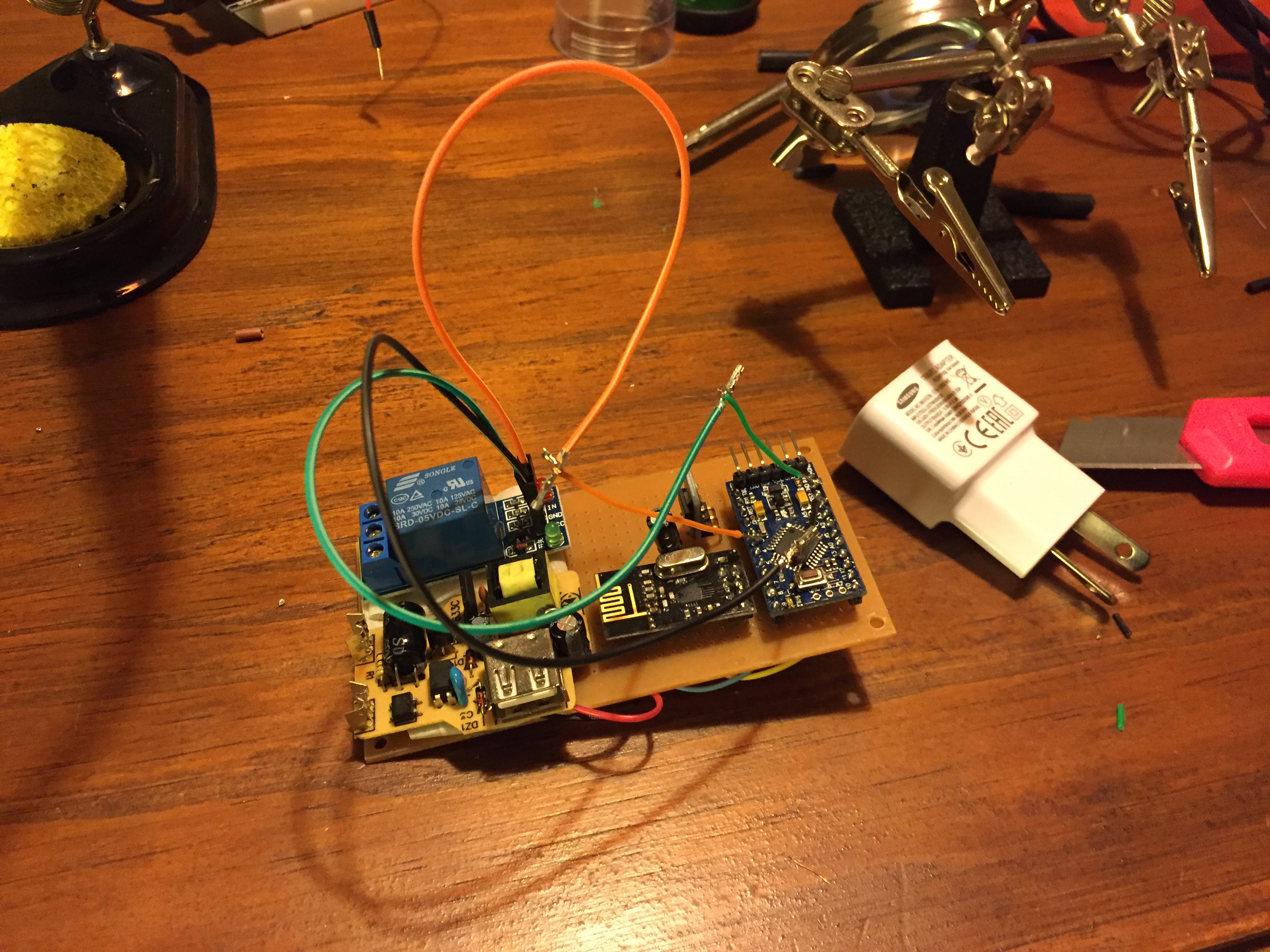
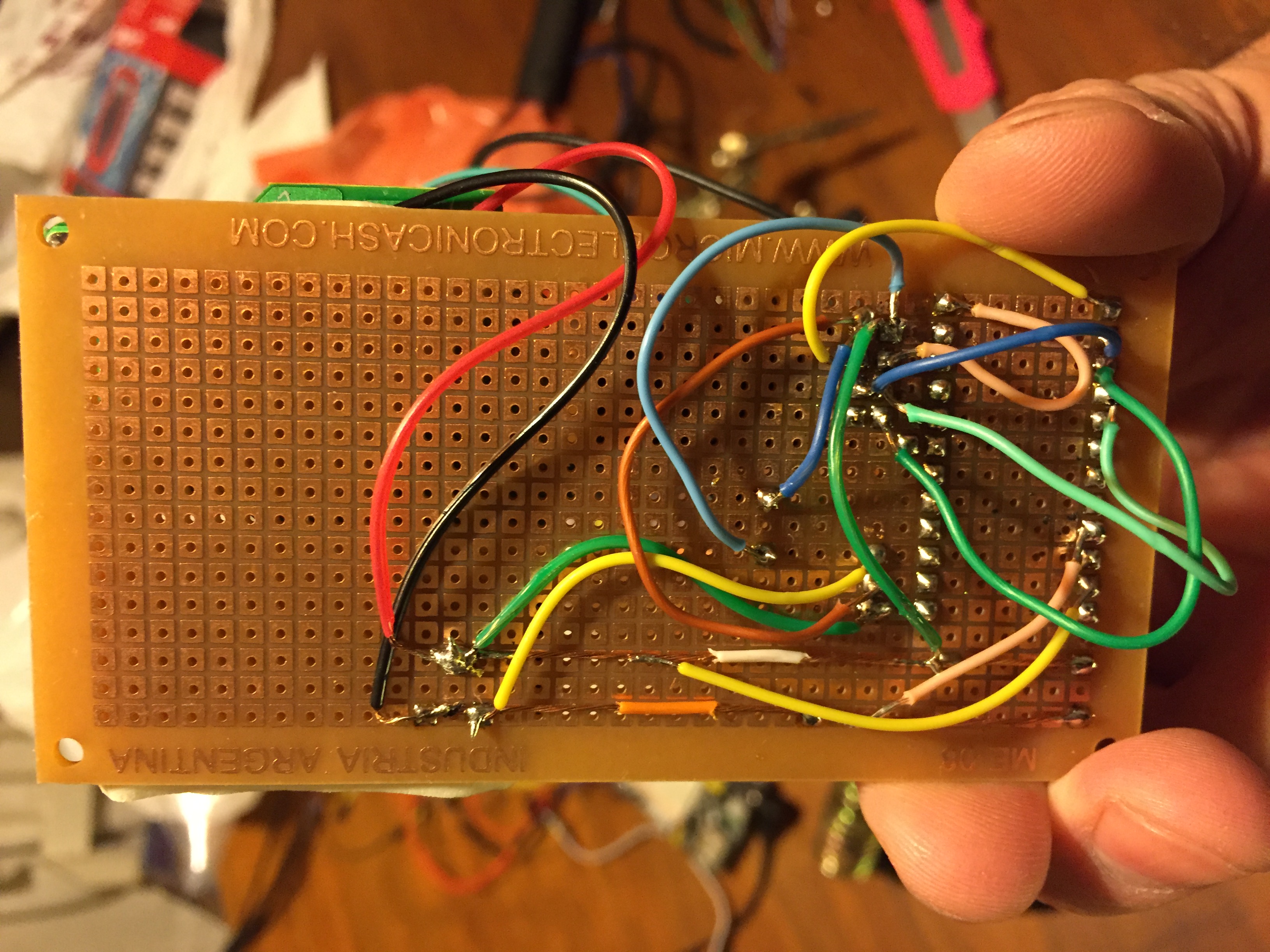
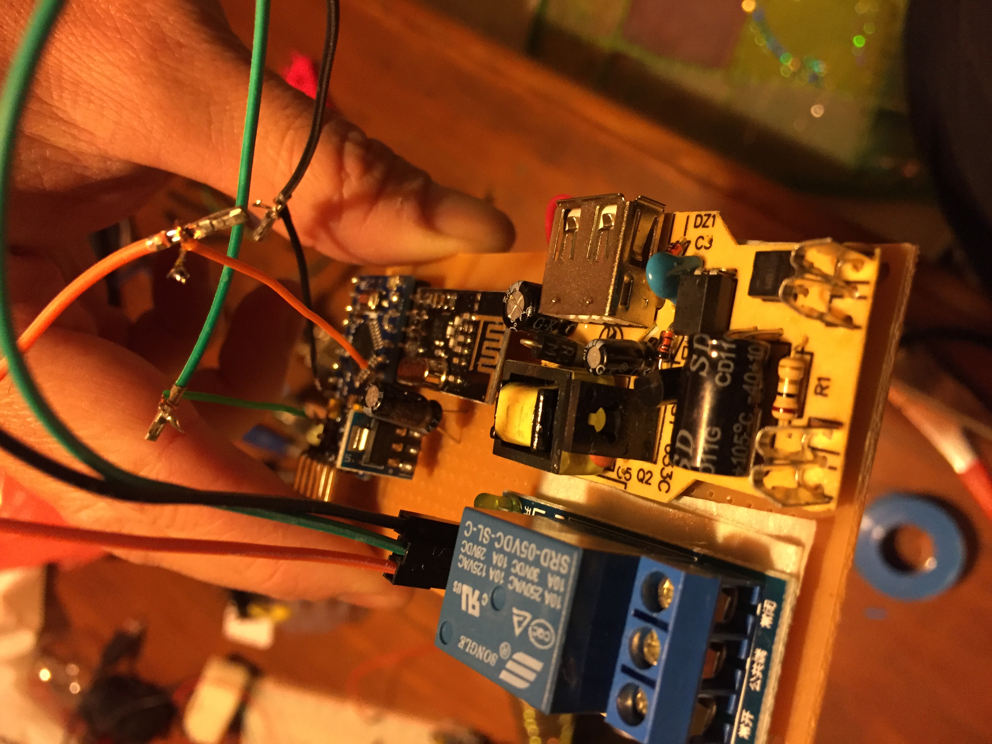
I'm not finished my board, but here are some pictures showing how I assembled all the pieces
Video: Show how is The Relay is Working