Navigation

    • Register
    • Login
    • OpenHardware.io
    • Categories
    • Recent
    • Tags
    • Popular
    1. Home
    2. the cosmic gate
    3. Best
    • Profile
    • Following
    • Followers
    • Topics
    • Posts
    • Best
    • Groups

    Best posts made by the cosmic gate

    • RE: 110v-230v AC to Mysensors PCB board

      @aproxx said:

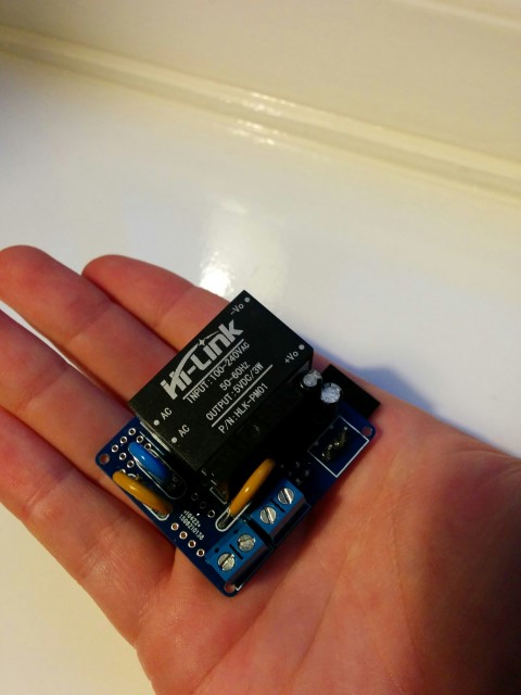
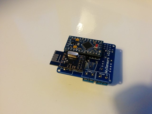
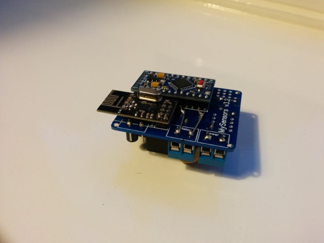
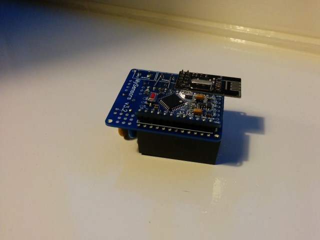
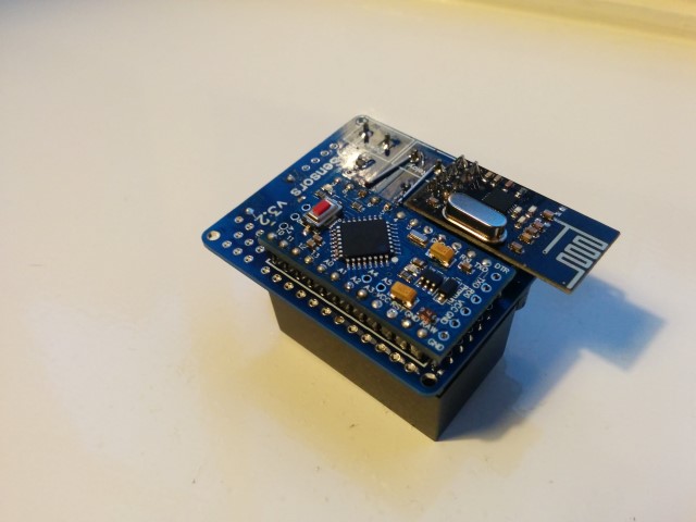
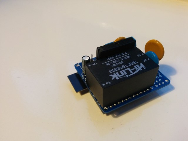
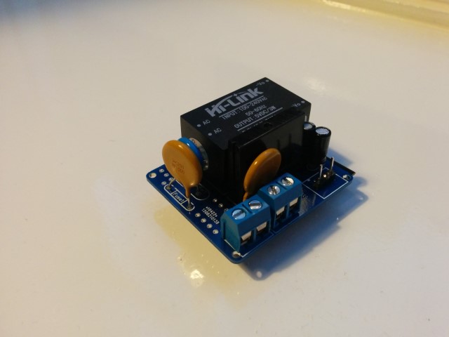
      For those who wanted to see some pictures of the board:
      IMG_20150921_194059 (Small).jpg IMG_20150921_194039 (Small).jpg IMG_20150921_194035 (Small).jpg IMG_20150921_194023 (Small).jpg IMG_20150921_192748 (Small).jpg IMG_20150921_192737 (Small).jpg IMG_20150921_192728 (Small).jpg

      Small notice: These pictures are of a slightly older design. The newer design has a few minor changes like better component placement and a permanent fuse instead of this resettable fuse. But these pictures should at least give you an idea on how everything looks like, and shows how really small it actually is.
      Also, I reinforced the traces of the 230v lines, which I absolutely recommend to do! (Although I do recommend to do it slightly more professional than I did on this prototype :))

      I really like this design, but it would be even nicer when this fits a ESP8266 🙂 Maybe the PCB could be even smaller . And it works together with link text .
      So is there maybe one of the PCB designer guys who can build /draw / design this 230v to ESP8266 PCB ?

      posted in Hardware
      the cosmic gate
      the cosmic gate
    • 3 in 1 incl battery monitor

      I'am trying to build some 3 in 1 ( motion / temp / hum ) incl. battery monitor .
      At the moment i try to combine these sketches , as result

      #include <SPI.h>
      #include <MySensor.h>  
      #include <DHT.h>  
      
      int BATTERY_SENSE_PIN = A0;  // select the input pin for the battery sense point
      
      #define CHILD_ID_HUM 0
      #define CHILD_ID_TEMP 1
      #define CHILD_ID_MOT 2   // Id of the sensor child
      #define HUMIDITY_SENSOR_DIGITAL_PIN 4
      
      #define DIGITAL_INPUT_SENSOR 3   // The digital input you attached your motion sensor.  (Only 2 and 3 generates interrupt!)
      #define INTERRUPT DIGITAL_INPUT_SENSOR-2 // Usually the interrupt = pin -2 (on uno/nano anyway)
      
      
      unsigned long SLEEP_TIME = 30000; // Sleep time between reads (in milliseconds)
      int oldBatteryPcnt = 0;
      
      MySensor gw;
      DHT dht;
      float lastTemp;
      float lastHum;
      boolean metric = true; 
      MyMessage msgHum(CHILD_ID_HUM, V_HUM);
      MyMessage msgTemp(CHILD_ID_TEMP, V_TEMP);
      MyMessage msgMot(CHILD_ID_MOT, V_TRIPPED);
      
      void setup()  
      { 
         // use the 1.1 V internal reference
      #if defined(__AVR_ATmega2560__)
         analogReference(INTERNAL1V1);
      #else
         analogReference(INTERNAL);
      #endif
        gw.begin();
        dht.setup(HUMIDITY_SENSOR_DIGITAL_PIN); 
      
        // Send the Sketch Version Information to the Gateway
        gw.sendSketchInfo("Humidity/Motion", "1.0");
      
      
       pinMode(DIGITAL_INPUT_SENSOR, INPUT);      // sets the motion sensor digital pin as input
       
        // Register all sensors to gw (they will be created as child devices)
        gw.present(CHILD_ID_HUM, S_HUM);
        gw.present(CHILD_ID_TEMP, S_TEMP);
        gw.present(CHILD_ID_MOT, S_MOTION);
         
        metric = gw.getConfig().isMetric;
      }
      
      void loop()      
      
      {  
        // get the battery Voltage
         int sensorValue = analogRead(BATTERY_SENSE_PIN);
         #ifdef DEBUG
         Serial.println(sensorValue);
         #endif
         
         // 1M, 470K divider across battery and using internal ADC ref of 1.1V
         // Sense point is bypassed with 0.1 uF cap to reduce noise at that point
         // ((1e6+470e3)/470e3)*1.1 = Vmax = 3.44 Volts
         // 3.44/1023 = Volts per bit = 0.003363075
         float batteryV  = sensorValue * 0.003363075;
         int batteryPcnt = sensorValue / 10;
      
         #ifdef DEBUG
         Serial.print("Battery Voltage: ");
         Serial.print(batteryV);
         Serial.println(" V");
      
         Serial.print("Battery percent: ");
         Serial.print(batteryPcnt);
         Serial.println(" %");
         #endif
      
         if (oldBatteryPcnt != batteryPcnt) {
           // Power up radio after sleep
           gw.sendBatteryLevel(batteryPcnt);
           oldBatteryPcnt = batteryPcnt;
         }
           
           
        // Read digital motion value
        boolean tripped = digitalRead(DIGITAL_INPUT_SENSOR) == HIGH; 
              
        Serial.println(tripped);
        gw.send(msgMot.set(tripped?"1":"0"));  // Send tripped value to gw 
        
        delay(dht.getMinimumSamplingPeriod());
      
        float temperature = dht.getTemperature();
        if (isnan(temperature)) {
            Serial.println("Failed reading temperature from DHT");
        } else if (temperature != lastTemp) {
          lastTemp = temperature;
          if (!metric) {
            temperature = dht.toFahrenheit(temperature);
          }
          gw.send(msgTemp.set(temperature, 1));
          Serial.print("T: ");
          Serial.println(temperature);
        }
        
        float humidity = dht.getHumidity();
        if (isnan(humidity)) {
            Serial.println("Failed reading humidity from DHT");
        } else if (humidity != lastHum) {
            lastHum = humidity;
            gw.send(msgHum.set(humidity, 1));
            Serial.print("H: ");
            Serial.println(humidity);
        }


        // Sleep until interrupt comes in on motion sensor. Send update every two minute. 
        gw.sleep(INTERRUPT,CHANGE, SLEEP_TIME);
      }


      Would this work ? ( sketch verification is okay 🙂 )

      posted in My Project
      the cosmic gate
      the cosmic gate
    • Watermeter Elster V200 PR6P:1

      Busy using / building a sensor like :
      alt text

      The sensor ( inductive) i use :LJ12A3-4-Z/BY as seen on the picture.

      I use the standaard water sensor sketch as found mysensors water sensor

      When i tested everything it seems to work together with domoticz ( after i changed this bij "hand" to: water).

      But how to find out about the pulses , or how to calculate this ?
      By default in the sketch it says:

      double ppl = ((double)PULSE_FACTOR)/1000;        // Pulses per liter
      

      But i want to know if this i right (or not)

      And the next thing to think about because this sensors is 10cm from the mysensors gateway : is it possible to connect this to the gateway so i dont have to build/use the extra arduino and radio as used now .
      Short: is it possible to combine this watersensor sketch with the gateway sketch and aruindo + RF radio

      posted in My Project
      the cosmic gate
      the cosmic gate