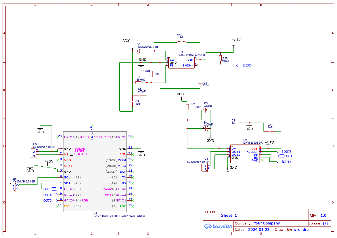
Thank you for your feedback; I will implement all of this in my design. As for the battery, I will go with a Li-Po Battery type: 304048 3.7V 1200mAh
wrendral
Posts
-
"Remote Irrigation with LoRaWAN: LM27313 Challenges and PCB Design" -
"Remote Irrigation with LoRaWAN: LM27313 Challenges and PCB Design"@eiten said in "Remote Irrigation with LoRaWAN: LM27313 Challenges and PCB Design":
Thank you very much for your feedback! I used TI Webench, it's super helpful. As you can see in my schematic, I have 4400uF of capacitance to power my H-bridge. The capacitors are charged through a 100Ω resistor to limit the current from the LM27313. Is this resistor really necessary? Or will the LM27313 just go into saturation? Or will it overheat and burn?

-
"Remote Irrigation with LoRaWAN: LM27313 Challenges and PCB Design"@eiten said in "Remote Irrigation with LoRaWAN: LM27313 Challenges and PCB Design":
Also, the DRV8837 does not fit because it needs a PWM
What do you think about the DRV8838 module?
The DRV8838 device is controlled using a PHASE/ENABLE interface. This interface uses one pin to control the H-bridge current direction, and one pin to enable or disable the H-bridge -
"Remote Irrigation with LoRaWAN: LM27313 Challenges and PCB Design"Thank you for your response.
It is indeed lacking context. I am a market gardener, and I have a water network for irrigation. I already use 'Rain Bird 100 DV 1'' M 9V' valves. The solenoid is a latching solenoid, so there is no need for a continuous current to keep the valve open. It requires a pulse of 1.5A for 100ms to change its state, depending on the applied polarity. Hence, the use of the H-bridge.
For the battery, it's a simple lithium-ion managed by the HTCC-AB01. This module is even capable of handling recharging via a small solar panel in the range of 5-7V.
My challenge lies in selecting passive components around the boost transformer and making routing decisions for my PCB. If there are experts out there, I'm all ears! I'm also looking for good references in books on the subject or online courses.
-
"Remote Irrigation with LoRaWAN: LM27313 Challenges and PCB Design"Hello everyone,
I hope this message finds you well. I'm currently working on an exciting project and would greatly appreciate your insights and advice.
Project Overview:
I am developing a remote irrigation system aimed at efficiently controlling irrigation valves from a distance. The primary objectives of this project include establishing long-distance communication using the LoRaWAN protocol, ensuring a minimum autonomy of 6 months for the system, and the capability to actuate an irrigation valve equipped with a DC latching solenoid.l have selected an architecture that includes the Heltec CubeCell HTCC-AB01 as microcontroller and LoRaWAN modulator, an LM27313 for voltage boosting, and an H-Bridge for solenoid control. However, I am facing some challenges and seeking your expertise.
You can find my schematic and PCB through this link :
https://oshwlab.com/wrendral/irrigationChallenges and Questions:
-
1 PCB Design and Routing: I am a novice in PCB layout and routing. Any remarks, tips, or suggestions on the PCB design would be welcomed.
-
2 LM27313 Datasheet: I find the LM27313 datasheet unclear, particularly in understanding how to dimension R1 and R2 to regulate the output voltage. Any insights or guidance on this would be highly appreciated.
-
3 PCB Design and Routing: I am a novice in PCB layout and routing. Any remarks, tips, or suggestions on the PCB design would be welcomed.
-
4 General Advice: If you have experience with similar projects or components and can provide general advice or potential pitfalls to avoid, please share your insights.
Thank you for your time and assistance!
Best regards,
-
-
PCB verification request for latching valve controllerHello,
Thanks for all your comments!!
I will implement all your improvement this weekend. I come back quickly. -
PCB verification request for latching valve controllerHello everyone.
I’m an engineer and a farmer.
I’m working one a cheap solution for irrigation control valve.My specifications :
Use latching valve.
Long range remote control ( 500m with some tree)
4 month automy
Under 50 euro per unit
My complete design will be :
A remote center, based around an arduino pro mini with 4g module and an RF Module
This base will receive my order from my phone and send it to slave control valve using RF Module.I’m currently working on the PCB of the slave Valve.
But i need some help to check if the solution used is valid.
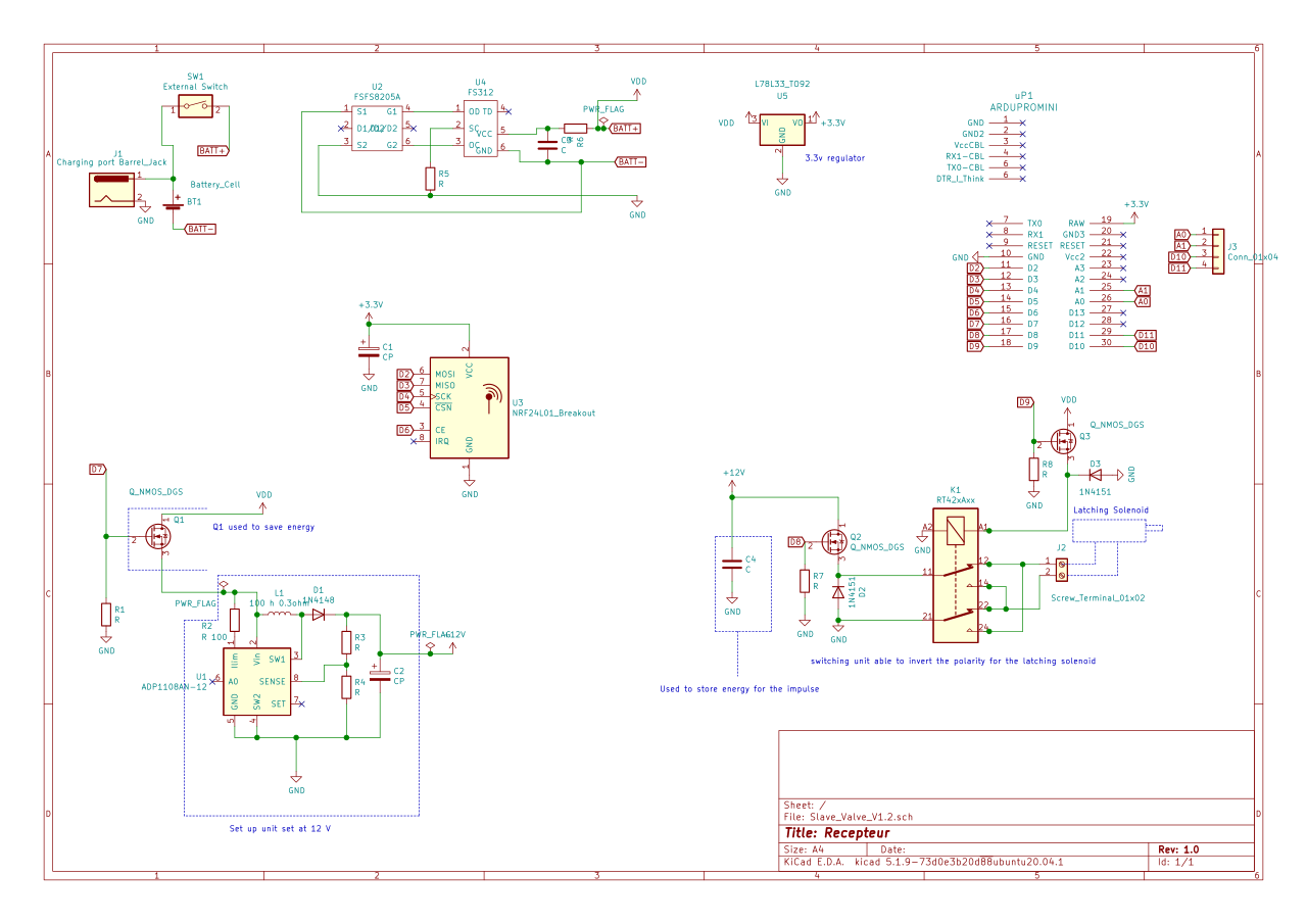
You will find all my work on git hub.To control a latching solenoid we need a circuit able to create a 100 ms 12v impulse through a 6 ohm solenoid.
On my schematic I create a step up module around a ADP1108.
I use a capacitor (C2) to store enough energy.
A Mosfet (controlled by an Arduino) and a 2 pole bistable relay are used to discharge this capacitor and switch the polarity if needed.!
I use an FS312 to secure my lipo battery.If the working principle is good I will calculate all the value of the components.
Do you see any problems on this PCB?
Thanks for your help.
Sorry for my rusty english.
