"Remote Irrigation with LoRaWAN: LM27313 Challenges and PCB Design"
-
Hello everyone,
I hope this message finds you well. I'm currently working on an exciting project and would greatly appreciate your insights and advice.
Project Overview:
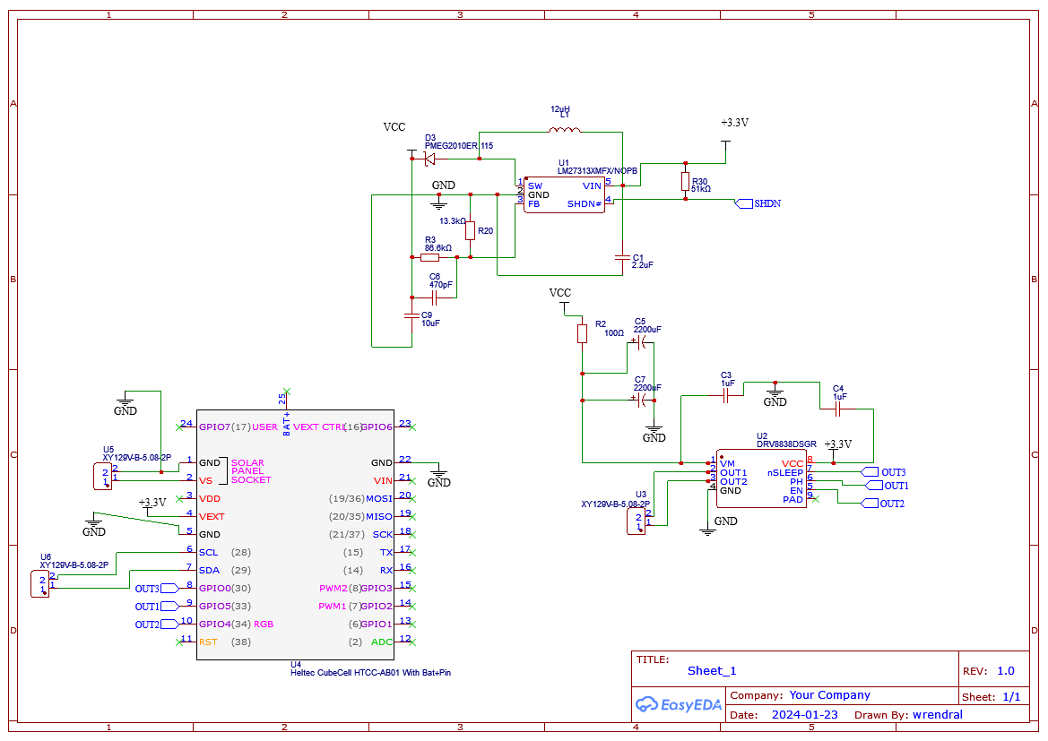
I am developing a remote irrigation system aimed at efficiently controlling irrigation valves from a distance. The primary objectives of this project include establishing long-distance communication using the LoRaWAN protocol, ensuring a minimum autonomy of 6 months for the system, and the capability to actuate an irrigation valve equipped with a DC latching solenoid.l have selected an architecture that includes the Heltec CubeCell HTCC-AB01 as microcontroller and LoRaWAN modulator, an LM27313 for voltage boosting, and an H-Bridge for solenoid control. However, I am facing some challenges and seeking your expertise.
You can find my schematic and PCB through this link :
https://oshwlab.com/wrendral/irrigationChallenges and Questions:
-
1 PCB Design and Routing: I am a novice in PCB layout and routing. Any remarks, tips, or suggestions on the PCB design would be welcomed.
-
2 LM27313 Datasheet: I find the LM27313 datasheet unclear, particularly in understanding how to dimension R1 and R2 to regulate the output voltage. Any insights or guidance on this would be highly appreciated.
-
3 PCB Design and Routing: I am a novice in PCB layout and routing. Any remarks, tips, or suggestions on the PCB design would be welcomed.
-
4 General Advice: If you have experience with similar projects or components and can provide general advice or potential pitfalls to avoid, please share your insights.
Thank you for your time and assistance!
Best regards,
-
-
Hi @wrendral
Maybe you should provide a little bit more Info about your Project:
- You write about autonomy. Is this battery powered? What kind of battery (chemistry, capacity, voltage)
- What are your solenoid needs? Voltage and current?
- If so, you write that you use a solenoid valve. In my experience, they are not so well suited for battery powered applications for several reasons:
- If you are battery powered, normaly you don't have a pump and your pressure is low. Solenoid valves need some pressure to work
- For irrigation, you want to deliver low rates of water during a longer time (like one to two hours) so the soil gets everything and you don't have to much evaopration. This leads to
- Solenoids need current all the time they are on and so drain the battery
For this reasons, I switched to motorized ball valves for my remote, solar powered irrigation projects.
If you want to stay with your solenoid, I don't think that you need a H-Bridge, as your solenoid does not need negative voltages. Also, the DRV8837 does not fit because it needs a PWM, switching on and off all the time. I made good experience with high side switches like the Infinion PROFET series. They also include short circuit detection and other things.
Maybe you write more about your requirements and then we could help you to find a solution that suits you best.
Regards, Edi
BTW: I'm very glad to hear you use the HTCC-AB01. I wrote the MySensors integration for the ASR6501 and never got real feedback. Someone is using it! YEAH! -
Thank you for your response.
It is indeed lacking context. I am a market gardener, and I have a water network for irrigation. I already use 'Rain Bird 100 DV 1'' M 9V' valves. The solenoid is a latching solenoid, so there is no need for a continuous current to keep the valve open. It requires a pulse of 1.5A for 100ms to change its state, depending on the applied polarity. Hence, the use of the H-bridge.
For the battery, it's a simple lithium-ion managed by the HTCC-AB01. This module is even capable of handling recharging via a small solar panel in the range of 5-7V.
My challenge lies in selecting passive components around the boost transformer and making routing decisions for my PCB. If there are experts out there, I'm all ears! I'm also looking for good references in books on the subject or online courses.
-
@eiten said in "Remote Irrigation with LoRaWAN: LM27313 Challenges and PCB Design":
Also, the DRV8837 does not fit because it needs a PWM
What do you think about the DRV8838 module?
The DRV8838 device is controlled using a PHASE/ENABLE interface. This interface uses one pin to control the H-bridge current direction, and one pin to enable or disable the H-bridge -
Thank you for your response.
It is indeed lacking context. I am a market gardener, and I have a water network for irrigation. I already use 'Rain Bird 100 DV 1'' M 9V' valves. The solenoid is a latching solenoid, so there is no need for a continuous current to keep the valve open. It requires a pulse of 1.5A for 100ms to change its state, depending on the applied polarity. Hence, the use of the H-bridge.
For the battery, it's a simple lithium-ion managed by the HTCC-AB01. This module is even capable of handling recharging via a small solar panel in the range of 5-7V.
My challenge lies in selecting passive components around the boost transformer and making routing decisions for my PCB. If there are experts out there, I'm all ears! I'm also looking for good references in books on the subject or online courses.
@wrendral said in "Remote Irrigation with LoRaWAN: LM27313 Challenges and PCB Design":
'Rain Bird 100 DV 1'' M 9V'
Hi @wrendral
Ah, I see. I don't find any useful information about this latching type on the internet. So guessing from the name and according to your informations, this valve needs a 100mS pulse, 9V @1.5A to switch on or off?
For the passive components around the LM27313, I'd reccomend to use the TI webbench (google for it), there you can enter your parameters and get a design proposal.
The problem might be the current you need for this short time. THe LM27313 can deliver at most 1A, and I don't know what your battery can deliver, but I don't think it's in the range of 5A. So you need a rather big capacitor after the LM27313. You can estimate it if you know what maximum voltage drop during the impulse your valve can accept, I could not find informations regarding this.
About the PWM: please ignore my remark, I had the wrong part in my mind. This driver has an internal boost and does not need PWM to bootstrap the Vgs.
Regards, Edi
-
@eiten said in "Remote Irrigation with LoRaWAN: LM27313 Challenges and PCB Design":
Thank you very much for your feedback! I used TI Webench, it's super helpful. As you can see in my schematic, I have 4400uF of capacitance to power my H-bridge. The capacitors are charged through a 100Ω resistor to limit the current from the LM27313. Is this resistor really necessary? Or will the LM27313 just go into saturation? Or will it overheat and burn?
-
Hey @wrendral
I don't have personal experience with the LM27313 I have to admit. But according to the data sheet, the device has cycle by cycle current limiting and thermal shutdown (see last sentence in Chapter 3). So I think regarding the switcher, you don't have problems. If the battery survives about 6 Amps for a short time after switch on, this should work very well without the 100 Ohm resistor.
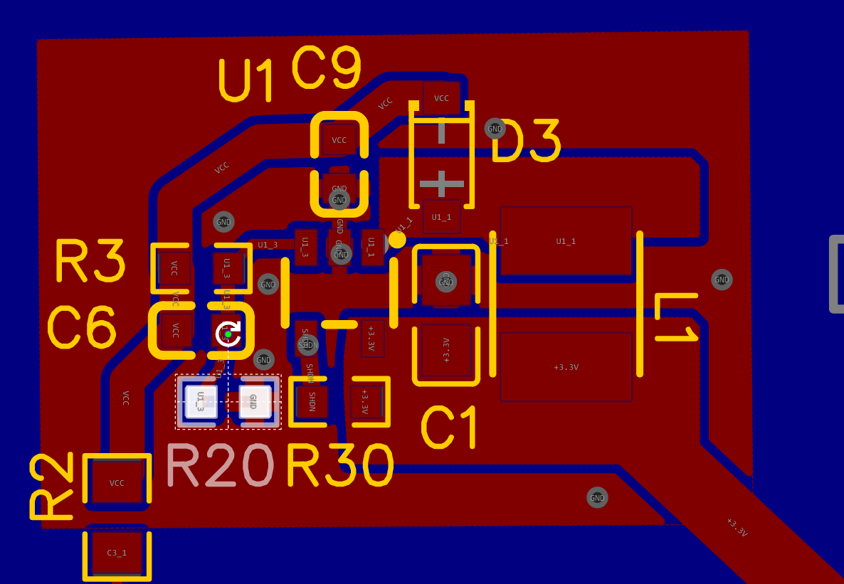
Regarding design: You have to make sure your switched current loops are as small as possible. So keep U1.5 - L1 - U1.1, U1.1 - D3 - U1.2 and U1.5 - C1 - U1.2 as short as possible.
I see you did a good job in your layout regarding this point.
What concerns me is the 3.3V connection to the LM27313 . There, you can have several amps of current, especially when switching on the LM, charging the capacitors. Let's say the LM limits the current to 1.5A on the 9 Volt side, then you have (including losses of the converter) about 4.5 Amps on the 3.3 V side. They have to go trough the 3.3V regulator on the Heltec board. I don't think it will survive it. And you have additional losses: Suppose you have a fully charged LiPo with 4.2 Volts. The regulator will first drop it to 3.3V, resulting in (4.2-3.3)V = 0.9V drop, 0.9V * 4.5A is over 4 Watt of thermal dissipation in the 3.3V regulator. I'd suggest you make a connection battery -> pcb, and from there a connection to the LM with MUCH wider traces than your 3.3V traces are now and another connection from the PCB to the Heltec battery pins.
Furthermore, I would add another ground plane on the top side, at least around the LM. Your ground traces are really to small there. See Figure 22 in the datasheet.
VCC also seems to be a bit thin.
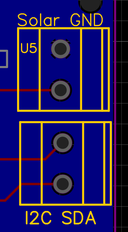
I'd put the comments for the connectors on the silkscreen layer, It's much better readable.Regards, Edi
-
@eiten said in "Remote Irrigation with LoRaWAN: LM27313 Challenges and PCB Design":
Thank you very much for your feedback! I used TI Webench, it's super helpful. As you can see in my schematic, I have 4400uF of capacitance to power my H-bridge. The capacitors are charged through a 100Ω resistor to limit the current from the LM27313. Is this resistor really necessary? Or will the LM27313 just go into saturation? Or will it overheat and burn?
-
Thank you for your feedback; I will implement all of this in my design. As for the battery, I will go with a Li-Po Battery type: 304048 3.7V 1200mAh
@wrendral said in "Remote Irrigation with LoRaWAN: LM27313 Challenges and PCB Design":
I will go with a Li-Po Battery type: 304048 3.7V 1200mAh
Might work, but maybe the internal protection will trigger with the high current peaks. I'd suggest you plan a 0 Ohm, (2512/THT) resistor as R2 and then replace it with a 100Ohm/1Watt if the protection triggers.
Hello! It looks like you're interested in this conversation, but you don't have an account yet.
Getting fed up of having to scroll through the same posts each visit? When you register for an account, you'll always come back to exactly where you were before, and choose to be notified of new replies (either via email, or push notification). You'll also be able to save bookmarks and upvote posts to show your appreciation to other community members.
With your input, this post could be even better 💗
Register Login