Controlling Blinds.com RF Dooya Motors with Arduino and Vera


  • Admin

    I recently figured out how to control my Blinds.com motorized cellular shades (http://www.blinds.com/control/product/productID,97658) with my Vera 3. The blinds have Dooya DV24CE motors (which use a 433 MHz RF for remote control) built into them but I couldn't find any already built RF transmitter that integrated directly with the Vera. I had recently started building Arduino sensors with Henrik's amazing MySensors Arduino Sensor Plugin (http://www.mysensors.org) so I decided to try to build my own. Thanks to many helpful resources on the internet I was able to control my blinds for less than $20 in Arduino parts.

    Here is a link to a YouTube video with an overview of the process: http://youtu.be/EorIqw-9eJw

    Here is a pdf with more info on the process if you are interested in doing it yourself:
    Controlling Blinds.com RF Dooya Motors with Arduino and Vera.pdf

    Arduino Code MySensors Version 2.x:
    https://gist.github.com/petewill/ac31b186291743e046f83497de0ffa87

    And the Arduino Code (OLD CODE):
    BlindsVera.ino

    2020-12-06: Edited to add updated code


  • Admin

    Thanks for the guide and Arduino sensor example @petewill .

    Really fun to read about how you sniffed the radio signal from your blinds! I had no idea it would be that "simple".


  • Admin

    I am working on an updated version of this code to include multiple remotes as well as send status back to Vera. I have the multiple remotes code working well but I'm running into problems updating the status. I don't think I'm understanding how to properly send an update to the S_COVER sensor type. I have read the API instructions 2 or 3 times but I'm not a coder so I'll admit I don't fully understand it all. I think that I should use this code to update the Vera: "gw.sendVariable(message.header.childId, V_UP, 100)" but it's not working as I thought would. Should I maybe be sending a 1 instead of a 100? Or, something else? When I look at the advanced settings the LoadLevelStatus is 100 when the blind is up (done through web interface) so I think sending 100 is correct. Maybe I should be sending it as a different variable like V_Dimmer? Here is my code where I'm sending the status back to Vera. Thanks!

          if (message.header.type==V_STOP){ //Stop
              unsigned char i;
              for(i=0;i<2;i++) {  
                blindAction(message.header.childId, 3); //blindAction(channel, action) action: 1=up, 2=down, 3=stop
                delay(100);
              }
              Serial.println("STOP command");
          }
          else if(incomingBlindData == 100 || message.header.type==V_UP){//100 = Open/Up
             unsigned char i;
             for(i=0;i<2;i++) {
               blindAction(message.header.childId, 1);
               delay(100);
             }
             Serial.println("UP command");
             gw.sendVariable(message.header.childId, V_UP, 100); // Update Vera with status of blinds (up/down) 
          }
          else if (incomingBlindData == 0 || message.header.type==V_DOWN) { //0 = Closed/Down
             unsigned char i;
             for(i=0;i<2;i++) { 
               blindAction(message.header.childId,2); 
               delay(100);
             }
             Serial.println("DOWN command");
             gw.sendVariable(message.header.childId, V_DOWN, 0); // Update Vera with status of blinds (up/down)
       
          }
    

    S_Cover Advanced Settings.png


  • Admin

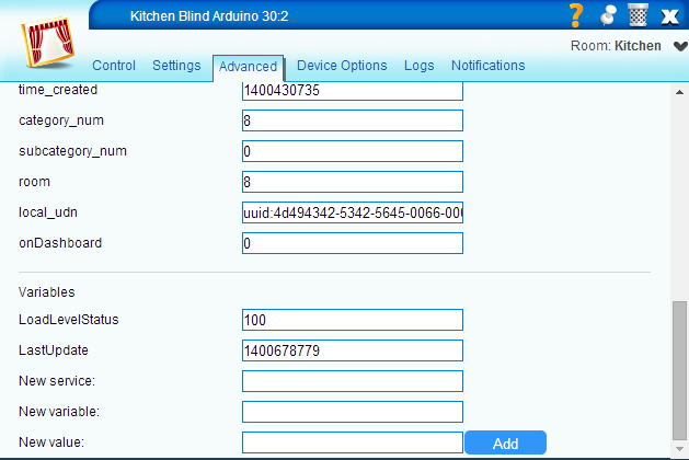
    UP/DOWN/STOP is commands and does not have any values associated with them.

    And yes, LoadLevelStatus is updated by setting dimmer value.


  • Admin

    @hek
    Excellent, thank you! Now to make some code changes and test some more.


  • Hero Member

    Really cool Pete...
    Ive some blind motors on the way..they are not RF though..so don't think ill need to decode the RF but thanks for the video explaining how it is done!

    Cheers,
    Greg


  • Admin

    @gregl You're welcome. I have received much more help than I have given but I do try to help when I can. Thanks for your posts as well. This community is great!


  • Awesome work!

    Is three anyway to copy a ROLLING code?


  • Admin

    @C.r.a.z.y. Not sure but I'm guessing it wouldn't be as easy as this since it is used for security. I would guess there is some key that it uses to generate the codes and you would need to figure that out. All just guesses though.


  • This post is deleted!


  • 433mhz-outlet
    please check this ;

    http://forum.mysensors.org/topic/713/433mhz-outlet


  • Admin

    Here is the updated code for 1.4 if anyone needs it...
    https://codebender.cc/sketch:67780


  • Contest Winner

    @petewill

    great to see the update... gives me another thing to do!


  • @petewill Thank you Pete. I tried this code and found 9 devices. I changed 433 codes but didnt work.

    Before mySensors how can i test the 433 code if it works or not?

    Are these settings correct?
    1101010101011100000000110
    1101010101011100000011000

    define SEND_DATA 3 //Data pin for RF Transmitter
    define ZERO_HIGH 270 //Delay for the high part of a 0 in microseconds
    define ZERO_LOW 950 //Delay for the low part of a 0 in microseconds
    define ONE_HIGH 910 //Delay for the high part of a 1 in microseconds
    define ONE_LOW 300//Delay for the low part of a 1 in microseconds

    Audocity file : http://1drv.ms/1wmgh2e

    https://codebender.cc/sketch:67840


  • Admin

    @C.r.a.z.y. This code is designed specifically for my blinds. You will need to modify it for your outlets based on the pattern of the code that is being sent. I took a look at your audacity file but I'm not exactly sure what I'm looking at. Did you press the On button 3 times then the Off button 3 times?
    As far as testing, what I did was just start with one command (On or Off in your case) and put it all in the loop function. Just put it an if statement so it only executes once. It will execute once when you plug in the arduino. Then you can get it sending the right codes correctly and not worry about the Vera setup.


  • Admin

    @C.r.a.z.y. Also, I forgot to mention this in my post above but you may want to consider making outlets with HEKs sketch. That's what I ended up doing because then I could see the status. With the RF stuff you can only send a signal but you don't get an acknowledgment as to if it worked or not.

    EDIT: I made my own outlets using HEKs relay sketch. That's how I see the status. I didn't end up using RF for outlets although I had originally planned to. I realized I wasn't very clear in my post above.


  • @petewill thank you Pete. I will try to modify at least i will sent rf code. Yes audocity file pressed 3 times on + 3 times off..


  • I think these are not the same with youtube video?

    define SEND_DATA 3 //Data pin for RF Transmitter
    define ZERO_HIGH 270 //Delay for the high part of a 0 in microseconds
    define ZERO_LOW 950 //Delay for the low part of a 0 in microseconds
    define ONE_HIGH 910 //Delay for the high part of a 1 in microseconds
    define ONE_LOW 300//Delay for the low part of a 1 in microseconds

    I read one of my remote with RC-Switch but other remote didnt work with RC-Switch.

    Your method is more general because RC-Switch only reads some kind of chipsets... SC5262 / SC5272, HX2262 / HX2272, PT2262 / PT2272, EV1527, RT1527, FP1527 or HS1527

    How can i convert this data to 32bit?
    1101 0101 0101 1100 0000 0011 0

    first 4 bits 0000 in your sketch + 25 bits from my remote = 29 bits


  • Admin

    @C.r.a.z.y. I am doing my best to understand but I think I'm still missing something. Basically what you want to do is to reproduce the pattern you recorded in Audacity. I did this somewhat crudely with blindAction function (someone smarter than me could code it much better but it works). You will need to modify (and probably rename) this function to meet your needs. In this function I call other functions (fourBits and eightBits) to actually send the RF signal out. I would start with these methods to get your timings right. You can then record what you send out in Audacity and compare. After you have got this working with one command you can work on interfacing it with Vera. I hope that helps a little.


  • @petewill Thank you i know you are very helpful. I tried to copy my remote to an universal remote learner(which has no name chipset) but it didnt copy. It is hard to understand and solve for a newbie.

    I simply tried to send 10101010codes with this sketch https://code.google.com/p/rc-switch/wiki/HowTo_Send?tm=6 and didnt work.

    Something interesting i found while tranmitting,
    If i remove the delay () than signal is always sent. I made a jammer! 🙂 Any of my 433 remotes didnt work!

    I want to learn if any universal remote learner with EV1527 Chipset works with RCSwitch?
    My plan is to copy some remote codes to EV1527 universal remote and read the code from serial with RCSwitch-rfSniffer.

    Now i will try IR SENDER-RECEIVER http://www.mysensors.org/build/ir maybe i can get new ideas for 433mhz things..


  • Admin

    @C.r.a.z.y. Yeah, I couldn't get the automatic "sniffers" to work for me either. Hopefully you're able to get it working. Remember, just focus on sending the 1's and 0's pattern. Start your code with that then expand when you get that part working. One thing that may help is to record what you're sending in Audacity again. That way you can compare the waveforms and see what needs to be modified with the code.


  • @petewill Comparing is great idea thanks i will try this!


  • Admin

    @C.r.a.z.y. You have probably already figured out a solution but I finally was able to make a video of my MySensors "Smart Plug". Here is the link: http://forum.mysensors.org/topic/775/8-lamp-outlet-smart-plug-module
    Just another way of doing what you're trying to do, but this way you will get the status reported instead of just hoping the outlet turned on.


  • I'm trying to do the same but my RF code is different. The number of bits is the same. I have first 20 bits witch I can set for remote 1;2;3 but the last 20 bits depands on command.
    I delete remote1Bits4, and channel (child_Id) and add eightBits action1;2;3 for up\down\stop But it dont work.
    Could you check this code changes, please?

    Remote 1
    1100 01111100 01001000 00110000 0011 01011110 up
    1100 01111100 01001000 10100000 0011 01010111 stop
    1100 01111100 01001000 10000000 0011 01010100 down
    Remote2
    0100 01110010 01001000 00110000 0011 01011110 up
    0100 01110010 01001000 10100000 0011 01010111 stop
    0100 01110010 01001000 10000000 0011 01010100 down
    Remote3
    1110 00100100 01001000 00110000 0011 11101000 up
    1110 00100100 01001000 10100000 0011 11100001 stop
    1110 00100100 01001000 10000000 0011 11100011 down

    /*
    //  This program is free software; you can redistribute it and/or
    //  modify it under the terms of the GNU General Public License
    //  version 2 as published by the Free Software Foundation.
    //
    //  DESCRIPTION
    //  This sketch provides a way to control blinds from www.blinds.com using a 433MHz RF
    //  signal. The motors in the blinds are Dooya DV24CE motors.
    //
    //  Watch a video of everything working together here: https://www.youtube.com/watch?v=EorIqw-9eJw
    //
    //  The sketch is based on Henrik Ekblad's <henrik.ekblad@gmail.com> MySensors project
    //  (http://www.mysensors.org).  Credit also goes to Ray (http://rayshobby.net/?p=3381)
    //  for instruction on how to decode the RF signal from the remote as well as code for
    //  sending the RF signal.
    //
    //  Developed by Pete B.
    //
    //  REVISION HISTORY
    //  Version 1.0 - March 19, 2014 - Original Program
    //  Version 1.1 - April 17, 2014 - Added support for multiple remotes that are programmed from blinds.com
    //  Version 1.2 - May 16, 2014 - Added gw.send() to update Vera blinds up/down status
    //  Version 1.3 - Nov 21, 2014 - Upgraded code to work with MySensors v1.4
    */
    
    
    //Include Vera related libraries
    #include <MySensor.h>
    #include <SPI.h>
    #include <EEPROM.h>
    #include <RF24.h>
    
    //Define Constants
    #define SEND_DATA 3 //Data pin for RF Transmitter
    #define ZERO_HIGH 395 //Delay for the high part of a 0 in microseconds
    #define ZERO_LOW 687 //Delay for the low part of a 0 in microseconds
    #define ONE_HIGH 750 //Delay for the high part of a 1 in microseconds
    #define ONE_LOW 333//Delay for the low part of a 1 in microseconds
    
    //Vera related constants
    
    // Set NODE_ID to something unique in your sensor network (1-254)
    // or set to AUTO if you want gw to assign a NODE_ID for you.
    #define NODE_ID auto
    
    /*
    //List all your blinds here.  These will have to be added as child nodes in setup()
    //The numbers will be used to assign the different remotes in the remote() method
    //So, make a note of which blind uses which remote then add it to the if statement
    //in remote().  This is referred to as the blindNumber in remote().
    */
    
    #define NUMBER_OF_BLINDS  3
    
    //Child Node Numbers
    //Family Room = Node 1, Remote 2, Channel 1
    //Kitchen = Node 2, Remote 2, Channel 2
    //Dining Room = Node 3, Remote 2, Channel 3
    //Kid's Room = Node 4, Remote 1, Channel 1
    //Kids's Room = Node 5, Remote 1, Channel 2
    //Guest Room = Node 6, Remote 1, Channel 3
    //Master Bedroom = Node 7, Remote 1, Channel 4
    //Master Closet = Node 8, Remote 1, Channel 5
    //Living Room = Node 9, Remote 2, Channel 4
    
    
    MySensor gw;
    
    /*
    //These 28 standard bits appear at the beginning of each transmit sequence:
    //0111011100000101010111001011.  They are then followed by 12 other
    //bits depending on the command being sent to the blind.  These bits
    //distinguish between the different remotes.
    //Because I'm not good at Arduino coding I needed to use someone else's
    //code to send the bits.  They only used 8 bits and I couldn't get any
    //more to send.  Because if this I have broken up the 28 bits into 8 bit
    //sections.  Make sure to put 4 zeros at the beginning of the first
    //sequence.  They will be ignored later in the code.
    //I added support for multiple remotes so you don't have to reprogram
    //anything when you buy more blinds.  Just add the additional remote codes.
    */
    
    //Remote One
    unsigned char remote1Bits1 = 0b00001100; //integer value of the 28 bit standard sequence referenced above. "0b" prefix is for ??
    unsigned char remote1Bits2 = 0b01111100;
    unsigned char remote1Bits3 = 0b01001000;
    
    //Remote Two
    unsigned char remote2Bits1 = 0b00000100; //integer value of the 28 bit standard sequence referenced above. "0b" prefix is for ??
    unsigned char remote2Bits2 = 0b01110010;
    unsigned char remote2Bits3 = 0b01001000;
    
    //Remote Three
    unsigned char remote3Bits1 = 0b00001110; //integer value of the 28 bit standard sequence referenced above. "0b" prefix is for ??
    unsigned char remote3Bits2 = 0b00100100;
    unsigned char remote3Bits3 = 0b01001000;
    
    //Remote codes will be put in standardBits with remote() method, depending on which remote is used
    unsigned char standardBits1 = 0b00000000;
    unsigned char standardBits2 = 0b00000000;
    unsigned char standardBits3 = 0b00000000;
    
    
    void setup()
    {
    
    	gw.begin(incomingMessage, NODE_ID);
    
    	// Send the sketch version information to the gateway and Controller
    	gw.sendSketchInfo("Blind Control", "1.3");
    
    	// Register sensors to gw (they will be created as child devices)
    	for (int i = 0; i < NUMBER_OF_BLINDS; i++)
    	{
    		gw.present(i + 1, S_COVER);
    	}
    }
    
    void loop()
    {
    	gw.process();
    }
    
    void incomingMessage(const MyMessage &message)
    {
    
    
    	Serial.print("Blind Channel: ");
    	Serial.println(message.sensor);
    	Serial.print("Message Data: ");
    	Serial.println(message.data);
    	Serial.print("Message Type: ");
    	Serial.println(message.type);
    
    	int incomingBlindData = atoi(message.data);
    
    
    	if (message.type == V_STOP) //Stop
    	{
    		//unsigned char i;
    		for(uint8_t i = 0; i < 2; i++)
    		{
    			blindAction(message.sensor, 3); //blindAction(channel, action) action: 1=up, 2=down, 3=stop
    			delay(50);
    		}
    		Serial.println("STOP command");
    	}
    	else if(incomingBlindData == 100 || message.type == V_UP) //100 = Open/Up
    	{
    		//unsigned char i;
    		for(uint8_t i = 0; i < 2; i++)
    		{
    			blindAction(message.sensor, 1);
    			delay(50);
    		}
    		Serial.println("UP command");
    		//gw.sendgw.send(message.sensor, V_DIMMER, 100); // Update Vera with status of blinds (up/down)
    		MyMessage blindMsg(message.sensor, V_DIMMER); //may need to assign message.sensor to a variable if this doesn't work
    		gw.send(blindMsg.set(100)); // Update Vera with status of blinds (up/down)
    	}
    	else if (incomingBlindData == 0 || message.type == V_DOWN) //0 = Closed/Down
    	{
    		//unsigned char i;
    		for(uint8_t i = 0; i < 2; i++)
    		{
    			blindAction(message.sensor, 2);
    			delay(50);
    		}
    		Serial.println("DOWN command");
    		MyMessage blindMsg(message.sensor, V_DIMMER); //may need to assign message.sensor to a variable if this doesn't work
    		//gw.send(message.sensor, V_DIMMER, 0); // Update Vera with status of blinds (up/down)
    		gw.send(blindMsg.set(0)); // Update Vera with status of blinds (up/down)
    	}
    
    }


    void remote(int remoteNum)
    {
    	if (remoteNum == 1)  //Which remote will be used?
    	{
    		standardBits1 = remote1Bits1;  //Assign remote specific codes to standardBits variable used throughout the code
    		standardBits2 = remote1Bits2;
    		standardBits3 = remote1Bits3;
    	}
    	else if
    	{
    		standardBits1 = remote2Bits1;  //Assign remote specific codes to standardBits variable used throughout the code
    		standardBits2 = remote2Bits2;
    		standardBits3 = remote2Bits3;
    	}
    	else
    	{
    		standardBits1 = remote3Bits1;  //Assign remote specific codes to standardBits variable used throughout the code
    		standardBits2 = remote3Bits2;
    		standardBits3 = remote3Bits3;
    	}
    }
    
    void fourBits(unsigned char bits)
    {
    
    	unsigned char i;
    	int delayTime;
    
    	for(i = 0; i < 4; i++)
    	{
    		int highTime;
    		int lowTime;
    		delayTime = ((bits >> (3 - i)) & 1 ? 1 : 0);
    
    		if (delayTime == 1)
    		{
    			highTime = ONE_HIGH;
    			lowTime = ONE_LOW;
    		}
    		else
    		{
    			highTime = ZERO_HIGH;
    			lowTime = ZERO_LOW;
    		}
    		digitalWrite(SEND_DATA, HIGH);
    		delayMicroseconds(highTime);
    		digitalWrite(SEND_DATA, LOW);
    		delayMicroseconds(lowTime);
    	}
    
    }
    
    void eightBits(unsigned char bits)
    {
    	unsigned char k;
    	int delayTime;
    	for(k = 0; k < 8; k++)
    	{
    		int highTime;
    		int lowTime;
    		delayTime = ((bits >> (7 - k)) & 1 ? 1 : 0);
    
    		if (delayTime == 1)
    		{
    			highTime = ONE_HIGH;
    			lowTime = ONE_LOW;
    		}
    		else
    		{
    			highTime = ZERO_HIGH;
    			lowTime = ZERO_LOW;
    		}
    		digitalWrite(SEND_DATA, HIGH);
    		delayMicroseconds(highTime);
    		digitalWrite(SEND_DATA, LOW);
    		delayMicroseconds(lowTime);
    	}
    }
    
    
    //Separator Delay Method (this is repeated frequently)
    void separatorDelay(boolean upDown)
    {
    	if(upDown == true)
    	{
    		digitalWrite(SEND_DATA, LOW);
    		delayMicroseconds(8020);
    	}
    	digitalWrite(SEND_DATA, HIGH);
    	delayMicroseconds(4812);
    	digitalWrite(SEND_DATA, LOW);
    	delayMicroseconds(1479);
    
    }
    
    void endDelay()
    {
    	digitalWrite(SEND_DATA, LOW);
    	delayMicroseconds(51895); //Time of delay at the end of each sequence
    }


    void blindAction(int a)
    {
    	//c or channel: Order on the remote from left to right 1-16 available
    	//a or action: 1=up, 2=down, 3=stop
    
    
    	unsigned char action;  //8 action bits.  Only the first 4 bits are used in the up/down end sequence
    	unsigned char action2; //Last 4 bits from the up/down end sequence
    	unsigned char action3; //Last 4 bits from the up/down end sequence
    
    	if(a == 1)
    	{
    		action = 0b00110000; //code for up
    		action2 = 0b00110101;
    		action3 = 0b00001110;
    	}
    	else if (a == 2)
    	{
    		action = 0b00010001; //code for down
    		action2 = 0b00001110;
    		action3 = 0b00001110;
    	}
    	else (a == 3)
    	{
    		action = 0b00010001; //code for down
    		action2 = 0b00001110;
    		action3 = 0b00001110;
    	}
    
    	int i = 0;
    	//first 6 transmissions are the same for each blind action (up, down & stop)
    	while(i < 6)
    	{
    		separatorDelay(false); //false unless in the last part of the up or down commands
    		fourBits(standardBits1);
    		eightBits(standardBits2);
    		eightBits(standardBits3);
    		eightBits(action);
    		fourBits(action2);
    		eightBits(action3);
    		i++;
    	}
    
    
    	if (a == 3) //If a stop command is issued just send the end delay then exit the method
    	{
    		endDelay();
    	}
    	else //No stop issued so run through the last sequence
    	{
    		separatorDelay(false); //send true because we are in the up/down end sequence so there is an additional delay
    		fourBits(standardBits1);
    		eightBits(standardBits2);
    		eightBits(standardBits3);
    		eightBits(standardBits4);
    		eightBits(action);
    		fourBits(action2);
    		eightBits(action3);
    
    		int j = 0;
    		while(j < 3)
    		{
    			separatorDelay(true);
    			fourBits(standardBits1);
    			eightBits(standardBits2);
    			eightBits(standardBits3);
    			eightBits(standardBits4);
    			eightBits(action);
    			fourBits(action1);
    			eightBits(action2);
    			j++;
    		}
    		endDelay();
    	}
    }```

  • Admin

    @tjay4x4 sorry for the delayed reply. Are you using blinds.com blinds or something else? This code is written specifically for my blinds.com (dooya motors). They have a sequence of very specific codes that I reproduced with the blindAction method. If your remotes have different sequences you will need to modify the code there. If you are using blinds.com blinds, maybe they changed the sequences? Also, do your up/down/stop commands look the same as mine?


  • @petewill Thank you for reply!
    I'm using not blinds.com and this is really big problem. 🙂 I'm not a progarmmer, and now I have two ways
    1 solder relays to remote buttons. In this case I destroy remotes. Or order another 3 remotes for donation.
    2 ask somebody to change this sketch for a fee. It's better, but who can?


  • Admin

    @tjay4x4 I think you will find many helpful people on this forum. If you are willing to learn a little about coding there will be people to help. I have been helped many times with coding questions.

    Here is what you will need to do. First, you need to decode your signals. It seems you have done this already which is great. Once you have your signals decoded correctly you can test to make sure they work correctly by sending them without using anything but an arduino. This is done with this code:

    digitalWrite(SEND_DATA, HIGH);
    delayMicroseconds(highTime);
    digitalWrite(SEND_DATA, LOW);    
    delayMicroseconds(lowTime);
    

    SEND_DATA is the digital pin on the Arduino (defined above in the code) and the highTime/lowTime is how long it will remain high and low. You could literally do that for each 1 and 0 that is in your signal to make sure you have it correct. Once you have that down you can begin breaking it down into methods and patterns like I have..

    Hopefully that helps.

    Pete


  • @tjay4x4 How did you determine what your codes were? Did you use a RF library or did you 'sniff' them directly?


  • @petewill Thank you! Actually I dont trying my code just on arduino. You mean it could be different high and low time for 1 and 0 on my code. Well, then I went to check.


  • @Dwalt said:

    How did you determine what your codes were? Did you use a RF library or did you 'sniff' them directly?

    I used Audacity. As written in the instructions. For each button sequentially rewriting the code. Comparing them with Blinds.com it became clear that the differences in the combinations of digits. If in the original, the first 28 are the same, I have to differ for each controller first 12 digits and last 12 digits. UP, DOWN, STOP bits are the same for all remotes. The question is how to write it to this code? But first I need to check High and Low time.


  • Admin

    @tjay4x4

    Based on this it looks like you have 5 sets of 8 digits:

    Remote 1
    1100 01111100 01001000 00110000 0011 01011110 up
    1100 01111100 01001000 10100000 0011 01010111 stop
    1100 01111100 01001000 10000000 0011 01010100 down
    Remote2
    0100 01110010 01001000 00110000 0011 01011110 up
    0100 01110010 01001000 10100000 0011 01010111 stop
    0100 01110010 01001000 10000000 0011 01010100 down
    Remote3
    1110 00100100 01001000 00110000 0011 11101000 up
    1110 00100100 01001000 10100000 0011 11100001 stop
    1110 00100100 01001000 10000000 0011 11100011 down

    Here is some sample code that will allow you to test your sequence of 1s and 0s. It will run once each time the arduino is powered on. I haven't tested it but it should work ok.

    Put your delay values that you are figuring out in the _HIGH defines (at the top). The RF sender should be connected to pin 3 on the arduino. Also, make sure to change the standardBits variables to what you have figured out from Audacity.

    //Define Variables
    #define SEND_DATA 3 //Data pin for RF Transmitter
    #define ZERO_HIGH 376 //Delay for the high part of a 0 in microseconds
    #define ZERO_LOW 653 //Delay for the low part of a 0 in microseconds
    #define ONE_HIGH 713 //Delay for the high part of a 1 in microseconds
    #define ONE_LOW 317 //Delay for the low part of a 1 in microseconds
    
    int startUp = 1;
    
    unsigned char standardBits1 = 0b00000111; //integer value of the 28 bit standard sequence referenced above. "0b" prefix is for *******
    unsigned char standardBits2 = 0b01110000;
    unsigned char standardBits3 = 0b01010101;
    unsigned char standardBits4 = 0b11001011;
    unsigned char standardBits5 = 0b11001011;
    
    
    void setup() {
       
       Serial.begin(9600);
     
    }
    
    void loop() {
      if(startUp ==1){
      eightBits(standardBits1);
      eightBits(standardBits2);
      eightBits(standardBits3);
      eightBits(standardBits4);
      eightBits(standardBits5);
      startUp = 0;
      }
    
    }
    
    void eightBits(unsigned char bits){
        unsigned char k;
        int delayTime;
        for(k=0;k<8;k++) {
          int highTime;
          int lowTime;
          delayTime = ((bits>>(7-k)) & 1 ? 1 : 0); 
        
          if (delayTime == 1){
            highTime = ONE_HIGH;
            lowTime = ONE_LOW;
          }
          else {
            highTime = ZERO_HIGH;
            lowTime = ZERO_LOW;
          }
            digitalWrite(SEND_DATA, HIGH);
            delayMicroseconds(highTime);
            digitalWrite(SEND_DATA, LOW);    
            delayMicroseconds(lowTime);
        }
    }
    

    Also, when I was testing I recorded what was sent from my arduino (the above code) into Audacity so I could make sure my timings were correct.


  • This has been very useful, and I have been trying to use the same technique to see if I can control a Hunter Pacific fan that came with a Neoteric remote.

    However, if anyone else is looking to sniff RF signals, you might find the discussions here very interesting:
    http://www.princetronics.com/how-to-read-433-mhz-codes-w-arduino-433-mhz-receiver/

    Basically, you can use a 433 MHz receiver to sniff the signal without having to use a sound card etc. Would have saved me a bunch of time (but I did have fun trying to figure it out).

    However, I have now come unstuck as the signal from the remote I have appears to be encrypted in some way as the signal changes every time - each button press results in a different signal being sent. I will continue to see if I can figure it out, but I don't have too much hope.

    Thanks again for a very interesting project, and taking the time to write it up.

    Regards,
    CalvinAndHobbes


  • Admin

    @CalvinAndHobbes Thanks for sharing! I had originally tried to use that library to decode my remotes but it did not work. That's why I had to use the sound card. I agree though, definitely try that option first! It would be much easier.

    I didn't think Hunter fans communicated at 433MHz? I was trying to find a fan control last year that would allow me to integrate with MySensors but they all looked to be communicating at other frequencies (fans were down near 419MHz if memory serves correct). That's exciting that you were able to decode it though! What remote are you using?


  • Contest Winner

    Just a note that the Hunter remotes are relatively cheap and hackable if you just want to wire your arduino's outputs to the switches on the (cracked open) remote. you may even be able to fit a pro-miny and an RF radio into your existing remote and use it manually or via HA apps...


  • @BulldogLowell I started out by opening the remote to see if I could find any useful information, and you are correct - they are very simple and should be very easy to wire up a pro-mini inside it. What I don't know is whether I can have 2 remotes on the same fan, as I don't think I will get away (by the rest of the family :-)) with hacking the one we have. It was also an interesting exercise to see if I could figure out what the remote was doing.
    @petewill I am using the Neoteric remote from Hunter Pacific. Unfortunately they don't have any controllers that you can integrate in to any home automation system. I am going to contact the manufacturer to see if they will help, but I doubt it.


  • Admin

    @BulldogLowell I may have to go that route. It will probably be easier and cheaper for me anyway! First I need to finish the rain gauge 🙂

    @CalvinAndHobbes Yes, that would be nice if they had some integration but doubtful. There is a z-wave controller from Leviton (Leviton VRF01-1LZ Vizia RF) but it's over $100 normally. Too much for me.


  • @petewill I looked at the Leviton controller - but I am in Australia, and they don't make an Australian version (for some reason, Z-Wave in Australia is on a different frequency).
    And the fans I am using are Hunter Pacific fans made by an Australian company, and that is probably why the remote works on a different frequency. I believe Hunter and Hunter Pacific are different companies - just in case anyone gets them confused.


  • Admin

    @CalvinAndHobbes said:

    I believe Hunter and Hunter Pacific are different companies

    Yes, thanks for clarifying. I was thinking they were the same.

    Too many frequencies to worry about... I wish z-wave was all the same. It would simpler...


  • I contacted the manufacturer, and they confirmed the protocol is a proprietary one, but they suggested I hack the remote directly, and even offered to send me some remotes to play with, so I am going to go down that route. The remote is very easy to hack too.


  • Admin

    @CalvinAndHobbes said:

    but they suggested I hack the remote directly, and even offered to send me some remotes to play with

    Wow, that is awesome! Good work!


  • Hero Member

    @CalvinAndHobbes, @petewill ,

    I have a similar challenge, to automate some fans that I have in my house. I didn't have the same luck when contacting the manufacturer. I tried to hack the radio messages using both 433Mhz and 315Mhz sniffers, but they must use a different radio, or I did something wrong.

    It is relatively easy to hack my remotes and insert an Arduino + radio, however I'm thinking in other aspects before start --- Such as replacing the battery of the remote (currently a single CR2032 cell) , as it will have to be "always on" in order to listen to the gateway.

    I'm also think in do a 'bi-way' interface, so instead only listem gw and 'press buttons' in the remote, the inserted arduino would also sense if any button is pressed in the remote and report it back to GW.

    And my remotes uses the same key for on AND off. So unless I put another sensor nearby (or in) the fans, the gw will never 'be sure' if the fan is on or off...

    Just some thoughts about the topic...


  • Admin

    @rvendrame said:

    Just some thoughts about the topic...

    Thanks. I agree, there doesn't seem to be a perfect solution. For my blinds we rarely use the remotes that came with them. That way we don't need to worry about the status being incorrect. I have modified phones placed around the house we use as control panels as well as apps on our phones. But, for the most part the blinds are all controlled automatically by the light level outside. A ceiling fan would be different though I'd imagine.


  • Hi to everyone! Im very (I mean VERY) new at this, and Im far to be a programer or an specialist, Im just an enthusiastic end user willing to do all of you experts do!

    I have the same problem as Pete had, I have some dooya motors in my blinds and I want to integrate them to my smarthome system. This blinds are controlled by a remote control with 3 buttons, up – down – stop, and they are suppose to be RF, they have awesome range btw (see pics).

    IMG_3770.JPG
    IMG_3072.JPG IMG_3071.JPG IMG_3771.JPG

    First I tried the RC-Switch to sniff the RF code, but the program return nothing, just blank, that’s why I came to this, wich I would like to thank Pete for giving a light at the end of the tunel! (which Im still in).

    I did all the process to sniff the signal of the remotes, and this is what I got and traduced to binary:

    RFSalaBO.PNG

    Not the same wave structure (squared) but I hope it has nothing to do.

    Now Im in the process of testing this code just with the Arduino, but it doesn’t work! I followed the code Pete uploaded and change the highlighted parts with my code, please let me know if I did ok, this are what I changed:

    This first part, I used the first 28 bits of my signal, which is the same in the 3 comands:
    codepart1.PNG
    Here, I used the last 8 bits for each comand:
    codepart2.PNG

    Any clues what I might be doing wrong?

    Just in case, Im using an Arduino UNO, and I connected it this way:
    IMG_3772.JPG
    IMG_3775.JPG
    IMG_3774.JPG

    Thanks in advance!


  • @frantona Could you post your entire sketch? Did you measure the signal timing?


  • @Dwalt said:

    @frantona Could you post your entire sketch? Did you measure the signal timing?

    Hi! Thanks for your answer. Nope, I didnt measured the signal timing. I missed it. How should I do it?

    I will paste the full code this night when I arrive home, Im using the same one Pete posted few messages back.

    Thanks a lot!


  • @frantona Here is a tutorial on figuring out the timing. Pete's sketch uses the timing (length) for the high and low of both the ones and zeros (lines 35-38).

    Have you tried this with the RCSwitch or Remoteswitch libraries? They take all the guesswork out of sniffing signals although they don't work for all transmitters. [Edit: nevermind, i reread your post where you did say you tried RCSwitch].


  • What a great thread, thanks @petewill for all of the info. I can't wait to give this a try.
    After reading through all of this, am I correct in assuming that using the slider control (or programming a controller to open the shade to a certain %) has not been achieved?
    I was thinking about this a bit, and thought about perhaps using a few cheap magnetic door sensors along the edge of the window at different positions. You could then attach a small neodymium magnet to the back of the bottom edge of the shade that passes by the door sensors. Each of those door sensors could report a value back to the controller, indicating its position (ie 0,25,50,75,100), and if the MySensors node receives a slider value from the controller, you could round to the closest value, and raise/lower the shade until that value is achieved.
    I'm a complete MySensors/HA/Vera noob, so please excuse my ignorance if this is a ridiculous solution to a simple issue. 😁


  • Admin

    @Mike1082 You are correct. Slider control hasn't been achieved. I have thought about doing something like this but I haven't had too much of a need for it in the 1+ years I have had the blinds. Usually up or down is all I want. 🙂

    The one problem I could see with doing this is you will need some sort of device placed at the blind. Currently all you need is power (battery or hard wired) and this works. If you want to report values back, you will need another sensor there. Not a deal breaker but not ideal. Also, you would need a way to confirm that it stopped (in case the signal didn't get received from the blind). If you are seriously considering doing this you may want to look into using a reed switch and mounting it on the spindle that turns when the blinds go up/down. That way you get a cleaner install with more frequent updates.

    I'd love to see it if you end up doing it. It would be a fun project!


  • Hero Member

    @petewill
    Nice work!

    What kind of battery is powering the blinds.com motor and its receiver? From looking at your video, it appears the blinds.com receiver is constantly listening, and having a receiver constantly listening 24/7 all the time can take quite a lot of power (or, at least it would if it were using an NRF24L01+ or an RFM69, although I of course realize it isn't using either one of those).

    Blinds.com says it can take a refillable "wand" that gives 12 volts. So, would that be 8x D-cell batteries?

    Do you find that you need to change the battery in the receiver often?

    Just trying to get a feel for what it would take to be listening 24/7.


  • Admin

    @NeverDie Thanks! It is powered by 8 AA batteries in the battery wand. I actually hardwired mine though. I was able to get power to all my windows fairly easily (although my wife would disagree). So, unfortunately I have no idea how long they last. I feel like I remember people reporting about a year but I can't say where I remember that from.


  • @frantona

    Your code has an error in the 'action' section of the sketch.

    if(a==1){
              action = 0b0001000;  //code for up
    

    It is missing a digit or bit. It should read:

    if(a==1){
              action = 0b00010001; //code for up
    

    I also think you mixed the 'down' with 'stop' actions. Try this:

    if(a==1){
              action = 0b00010001; //code for up
              action2 = 0b00001110;
            }
            else if (a==2){
              action = 0b00010011; //code for down
              action2 = 0b00001100;
            }
            else if (a==3){
              action = 0b00010101; //code for stop
              action2 = 0b00000101;   
         }


  • Hardware Contributor

    I hope its ok that I use this thread for my question, because the topic 'kinda fits:
    does anyone know a (cheap) way to add a motor (that could be controlled by mysensor) to existing blinds? In theory you would only need a small motor I guess, but I am unsure how to connect that to the blinds..


  • Hello,

    there is an other way to control your shutters.

    Dooya shutter control

    It´s itegrated in FHEM. There are also the decryption at the shuttersignal. All 40 Bit and the explain to the 40 Bit.

    sorry for my weak english.

    Jarnsen


  • Hi @petewill , I've been trying to implement a similar setup to this for the past few days, however I've unfortunately been unsuccessful with the RF sniffing step. I've tried multiple RF receivers (I have a 10-pk), multiple resistors, and multiple audio cables, yet the feedback from Audacity appears the same whether I'm not doing anything or spamming the remote buttons:

    0_1463936657162_audacity1.jpg

    Top is with nothing being pressed, bottom is with hitting buttons on the remote. Might you know of any other possible troubleshooting options I could do? If it helps, below is the remote from blinds.com:

    0_1463936739804_blindsdotcom remote.jpg

    Any advice would be appreciated. Thanks!


  • Admin

    @Rantlers Sorry for the delayed reply... busy day back at work.

    Hmm. Did you zoom in on the audacity waveform? I had to zoom way in. If that doesn't show anything it may be that the remotes are at a different frequency now. That looks different than mine. Is there any indication which frequency the remote is on?

    Also, I was able to actually hear the signal on my speakers when I played it back. It sounded like high pitched digital noise. Do you hear anything like that?


  • @petewill Hi Pete, thanks for the response, no worries on the delay! I zoomed in every time I created a new recording, but I could never find a distinguishing pattern like the ones you had. Funny, I did suspect that the frequency from the remote could be different so I have a 10pk of 315mhz tx/rx coming in tomorrow. I'll be rather embarrassed if its as simple as that, but pleased at the same time!

    I listened to the playback in your youtube video a few times and the strange thing is it almost sounds like I'm getting static and digital noise throughout the entire recordings, regardless of whether I'm pressing buttons on the remote or not. I honestly don't know of anything that would be constantly spitting out a 433mhz signal though.

    I'll post an update after I get a chance to try the new receivers.


  • Admin

    @Rantlers Yeah, see if you can find what frequency that remote is communicating on. There must be some specs some where on the remote.


  • @petewill Checking back in, have good news & bad news...

    Bad News: No go on the 315mHz receivers. But that's because...

    Good News: I did some research on the remote since you said you didn't recognize it and was able to find the users manual online:

    http://www.automatedshadeinc.com/files/controls-hunterdouglas/powerplatinum_remote_guide_5110540054_0912.pdf

    According to this the RF signal is 2.4ghz (last page of the pdf). However, that being said, am I now SOL in replicating the RF sniffing step with your setup? The only 2.4ghz transceiver I was able to find is this one:

    http://www.amazon.com/Addicore-nRF24L01-Transceiver-Antistatic-Compatible/dp/B00E594ZX0/ref=sr_1_sc_1?s=pc&ie=UTF8&qid=1464286496&sr=1-1-spell&keywords=2.4ghz+transciever+arduino


  • Admin

    @Rantlers Dang! That's too bad. Are the blinds blinds.com brand or Hunter Douglas? I just want to make sure they didn't use a similar remote style but change the frequency.

    The NRF24 is what most of use for these projects so it might not be bad to order some to test. I'm not an expert on radio though so it may not be as easy to "sniff" the signal. I know @Yveaux has built a sniffer but that may only work for the MySensors network. Sorry I can't be more help!


  • Mod

    @petewill said:

    that may only work for the MySensors network

    It will only work for nRF24L01+ chips. It isn't limited to MySensors.


  • Are you sure you have the economy shades? Ive noticed they have disappeared from Blinds.com, or at least I don't see them anymore.


  • @jfeger said:

    Are you sure you have the economy shades? Ive noticed they have disappeared from Blinds.com, or at least I don't see them anymore.

    I just confirmed with Blinds.com online chat that the economy blinds aren't available anymore, or at least for now. They stated there was a defect in the motors, so they had to pull the product and work on a redesign. No timeline on a release.


  • Thanks!!! this was such a great help in getting my dooya blinds from aliexpress working over network.

    I couldn't get the test code above to work and my sequence was 40 bits, so i modified the code quite a bit and made it much more efficient. Here is the code if anyone needs to test their code on arduino.

    //Define Variables
    #define SEND_DATA 4 //Data pin for RF Transmitter
    #define ZERO_HIGH 363 //Delay for the high part of a 0 in microseconds
    #define ZERO_LOW 726 //Delay for the low part of a 0 in microseconds
    #define ONE_HIGH 726 //Delay for the high part of a 1 in microseconds
    #define ONE_LOW 363 //Delay for the low part of a 1 in microseconds
    
    void setup() {
      // put your setup code here, to run once:
    Serial.begin(9600);
    
    String code = "1100111101000001000111011011000100010001";  // Change your blinds code here
    Serial.println(code);
    
    Serial.println();
    
    for (int i=0; i <= 10; i++) {
    
      int delayTime;
      for(int k=0;k<40;k++) {                  //Change k max value here (40) is mine
        char code1 = code.charAt(k);
        int highTime;
        int lowTime;
        delayTime = ((int) code1) -48;        // 48 is zero in ASCII, so 48-48 = 0 as a number.
            if (delayTime == 1){
            highTime = ONE_HIGH;
            lowTime = ONE_LOW;
          }
          else {
            highTime = ZERO_HIGH;
            lowTime = ZERO_LOW;
          }
            digitalWrite(SEND_DATA, HIGH);
            delayMicroseconds(highTime);
            digitalWrite(SEND_DATA, LOW);    
            delayMicroseconds(lowTime);
    
      }
      Serial.println();
      Serial.print("Round:");
      Serial.print(i);
      Serial.println();
      delay(50);
    }
    
    
    }
    
    void loop() {
    
    }


  • Please help me,
    My remote is dooya. And sniff code:
    10000011 01000010 01001001 11100001 00110011 pause
    10000011 01000010 01001001 11100001 01010101 up
    10000011 01000010 01001001 11100001 00111100 down

    I had use USB Saleae Analyzer sniff code.

    But not work, 😞

    alt text


  • Mod

    @かいと please do not cross post. If people can help you they will respond. Be patient!


  • Admin

    @かいと The pattern for the control may have changed...? Because you have a recording of the remote I would try to record what you are sending with your transmitter and compare the waveform of the two devices. They should be identical. That is how I ended up figuring out the exact timing needed for my motors.


  • My remote alt text


  • Hi guys,
    I realise that this is quite an old thread, but i found it a useful source of info when looking for a solution for my 433MHz problem, so I thought I'd share some of my findings...

    We have a holiday home in Spain and it has some external 'awnings' that extend over the windows to provide shade from the sun. In Spain these are called Toldos. They operate using tubular motors controlled using 433MHz remote controls – one remote for each awning, three in total. I'd tried all the regular methods to sniff the 433MHz protocol, but none of the standard Arduino libraries would even acknowledge that the remote was sending out any sort of signal. Other remotes, such as garage door openers, PIR detectors etc work fine with my sniffer, so the hardware/software I was using is good.

    I eventually resorted to using my sound card and Audacity software to capture the transmissions from the remote controls and this work surprisingly well (I'd tried every digital approach you can imagine up to this point, including a logic analyser, and was reluctant to try the analogue approach but wish I’d trued it earlier).

    What I discovered is that when I press either the UP or the Down buttons on the remote, it transmits a timing pulse followed by 40 bits of data. At first I thought that this sequence was repeated 8 times, but I eventually realised that one 40-bit code was used for the first 4 repetitions of the data, followed by a different code for the next 4 repetitions. I later realised that whenever one of these buttons is pressed, the initial 40 bit code is transmitted continuously then the other code is transmitted 4 times when the button is released. When the button is pressed quickly I just get the 'Pressed' code 4 times followed by the 'Released' code 4 times.
    The Stop button works slightly differently - only one code is used and this is transmitted at least 4 times and will continue to be transmitted as long as the button is pressed. (in other words, the Stop button has a 'Pressed' code, but not a 'Released' code).

    It's actually the 'Pressed' code for each button that controls the awnings. The 'Released' code doesn't seem to serve any function with my awnings.
    These 'Released' codes really confused me to begin with, as I when I checked two different bursts of data from the same button using Audacity, I was getting different results. This was obviously because on one occasion I’d picked one of the ‘Pressed’ codes to analyse, but on the second occasion I’d inadvertently analysed a ‘Released’ code. At first I’d thought the analogue capture process was unreliable, but then I thought that maybe some sort of rolling code system was being used. I eventually realised what was going on, but not until I'd spent quite a bit of time cursing the remote control and the PC.
    I was able to replicate the transmitted code fairly accuracy using a version of @peashooter's code (thanks!) and this worked well
    I’m repeating the ‘Pressed’ code 4 times and it seems to work very reliably.

    As well as being able to control the awnings using an Arduino/ESP8266 transmitter, I also wanted to be able to use the existing handheld remotes, so to be able to understand the current position of each awning I needed a way of receiving the commands from the remotes and using them to keep track of each individual awning. This bought me back to the original problem of not being able to find a way to listen to the 433MHz messages from the remotes using any of the current Arduino libraries.
    In started delving into the idea of modifying the RC-Switch library, now that I knew the timing characteristics of the signals. At that point I stumbled across this small library:
    https://github.com/bjwelker/Raspi-Rollo

    It has an Arduino sketch that is written to identify the codes that are being transmitted by remote controllers for blinds, so that these codes can then be used to control the blinds using a Raspberry Pi.
    When I ran the Arduino sketch it immediately produced results from my Awning remotes – If only I’d found this earlier!
    The results it gives are in a “Quad Bit” format, but when I modified the code to print out the raw received codes they were identical to the results I’d obtained from Audacity.
    I’m not interested in using a Pi to transmit the codes to the blinds, and this wasn’t needed anyway, as using @peashooter's code I already had a transmission solution. I’m now in the process of fine-tuning the code that tracks each blind’s position based on the commands that are sent from either the hand-held remotes or my transmitter. The position is simply based on time between the start and stop transmissions and the known time that it takes to fully extend each awning.

    The primary reason for wanting to control the awnings is that when it gets windy, I want to be able to automatically retract them. I’m using data from a weather station to monitor the wind speed and if it meets the criteria (very strong winds for a short period, or not quite so strong winds for a slightly longer period, then the awnings will be retracted (assuming that they’re extended of course). I’m also automatically retracting them when it gets dark, as it’s easy to forget to do this and a bit cumbersome to walk around and do all three awnings using the separate hand-held remote controls.
    Here’s some pictures of one of the remotes:
    0_1531672414982_IMG_3613.jpg
    0_1531672435282_IMG_3611.jpg
    0_1531672454575_IMG_3610.jpg
    0_1531672467499_IMG_3609.jpg

    The brand name on the remote is Gaviota and the circuit board says “Designed by D Team” “DC104/105” “V2.1” and “No.DA288”.

    Here are what the awnings look like:

    0_1531672501926_IMG_3631.jpg
    I have no idea what the brand name is on the tubular motors, as they’re hidden inside the mechanism.
    Hopefully this saves someone at least some of the pain that I’ve been through to get to this point.

    Pete.


  • @petewill
    Great guide.
    I stumbled upon this when I realised that my Debel awning was using a Dooya motor and remote.

    I did not use your cool system with the soundcard to sniff the RF codes, but instead used my RTL-SDR usb receiver, since I already had it laying around 😀

    After finding the codes I programmed an Arduino with it and connected it to my OpenHAB installation. Now the awning can be controlled with the OpenHAB app, and my wife just loves it 😀

    Just wanted to point it out for others looking for RF codes for Debel awnings.


  • Admin

    @mortenvinding cool! I looked at a couple of code "sniffers" when I did this but none of them worked. Good to hear progress has been made on that. Should save quite a bit of time.


  • I recognize this is an old post, but I've not found any newer discussion and I have hit a roadblock. I've followed all of the very helpful posts to build a sniffer and decode it as tools like RCSwitch wouldn't work. I even used @PeteKnight 's tip to notice there was a different code sent initially when a button was pressed. I've tried sending both versions, emulating the initial (timing?) signal at the start. I tweaked the high and low delays and I think I've got a rf signal that is extremely close to the one from the remote. Here are the two different sources in audacity for comparison.
    ![0_1598212142451_RemoteInAudacity.JPG](Uploading 100%)

    //Define Variables
    #define GND 3
    #define VCC 4
    #define DATA 5 //Data pin for RF Transmitter
    #define ZERO_HIGH 307 //Delay for the high part of a 0 in microseconds
    #define ZERO_LOW 750 //Delay for the low part of a 0 in microseconds
    #define ONE_HIGH 648 //Delay for the high part of a 1 in microseconds
    #define ONE_LOW 409 //Delay for the low part of a 1 in microseconds
    
    int startUp = 1;
    
    unsigned char standardBits1 = 0b00001111; //integer value of the 28 bit standard sequence referenced above. "0b" prefix is for *******
    unsigned char standardBits2 = 0b01111100;
    unsigned char standardBits3 = 0b01100100;
    unsigned char standardBits4 = 0b00000001;
    unsigned char standardBits5 = 0b00011110;
    
    
    void setup() {
      pinMode(GND,OUTPUT);
      pinMode(VCC,OUTPUT);
      pinMode(DATA,INPUT);
      digitalWrite(GND,LOW);
      digitalWrite(VCC,HIGH);
      
       Serial.begin(9600);
     
    }
    
    void loop() {
     unsigned char i;
          delay(3000);
        if(startUp ==1){
        for(i=0;i<10;i++) {
          delay(1000);
          digitalWrite(DATA, HIGH);
          delayMicroseconds(5000);
          digitalWrite(DATA, LOW);    
          delayMicroseconds(1500);        
    
          eightBits(standardBits1);
          eightBits(standardBits2);
          eightBits(standardBits3);
          eightBits(standardBits4);
          eightBits(standardBits5);
          startUp = 0;
        }
     }
    }
          void eightBits(unsigned char bits){
          
              unsigned char k;
              int delayTime;
              for(k=0;k<8;k++) {
                int highTime;
                int lowTime;
                delayTime = ((bits>>(7-k)) & 1 ? 1 : 0); 
              
                if (delayTime == 1){
                  highTime = ONE_HIGH;
                  lowTime = ONE_LOW;
                }
                else {
                  highTime = ZERO_HIGH;
                  lowTime = ZERO_LOW;
                }
                  digitalWrite(DATA, HIGH);
                  delayMicroseconds(highTime);
                  digitalWrite(DATA, LOW);    
                  delayMicroseconds(lowTime);        
            }
         
    }
    

    Here are all the codes I was able to extract from audacity for one of the blinds.
    Down1: 00001111 01111100 01100100 00000001 00111100
    Up1: 00001111 01111100 01100100 00000001 00011110
    Stop1: 00001111 01111100 01100100 00000001 01010101
    Start1: 00001111 01111100 01100100 00000001 00010001
    Does anyone have an idea of what I might still be missing in getting this work?


  • Admin

    @ssuckow I can't see the image but when I did this I started in small steps. Your first goal is to send a successful signal without all the MySensors code. I just created a standalone program with all my code in the setup so when it ran it would send a raise, stop or lower signal. Once you do that you can integrate it with MySensors much easier. It sounds like you have mostly done this based on your description above but I'm not sure. Also, are you sure the hardware is wired correctly? Is the 433Mhz device is getting enough power to send the signal to the blinds?


  • @ssuckow said in Controlling Blinds.com RF Dooya Motors with Arduino and Vera:

    pinMode(DATA,INPUT);

    Why data pin is input? I think it should be output.


  • @petewill Sorry, it seems I had to use the .jpeg extension instead of .jpg. My code is just trying to move the blinds without any extra code. This image shows the remote signal on the top and the Arduino generated signal on the bottom.
    RemoteInAudacity.JPeG


  • @doteq You are correct. That was a holdover from when I was trying to sniff. I tweaked that and this image shows the updated version as Arduino7. Apparently it worked with it defined as input (as receiver connected to audacity was picking it up), but their was a lot more noise. Now, the signal looks very much like the source remote. However, It still doesn't move the blinds. 😞

    Capture.jpeg


  • From the code it looks like you're switching on the receiver by enabling the gnd and vcc pins with an output of the microcontroller. Do you have additional transistors to do so, or just with the output pins directly? In the last case I would recommend to connect it to gnd and vcc directly, to make sure enough current is available.


  • I just tried moving it to the VCC and ground pins and it didn't work either.


  • @ssuckow I managed to control blinds with your code. Make sure you have wire attached for antenna.


  • @ssuckow what you’ve posted seems to be a good match for the original.
    I’m wondering, based on your other comments, if your blinds need the message repeating several times (with my blinds it’s 4 times) or if the initial message is a sort of ‘stand by to receive a command’ instruction that needs to then be followed by the command message (maybe multiple times?).
    Try quickly stabbing at the remote control button whilst recording in Audacity and look at the bigger picture. This might give you a bigger picture of the complete command set that the remote is sending when a button is pressed.

    Pete.


  • @PeteKnight I'm also trying to control my Gaviota awnings with no success, my remote is not from Gaviota but a white label one (It says it uses rolling codes - it's the MX96 https://cloud.motorline.pt/download/manuais/eletronica/mx95-96-97_pt.pdf). I've tried decoding the codes with a cheap RF receiver hooked up with an ESP32 with espHome. I can get some codes sometimes, if I keep my finger pressed for a long time, but none of them work and they do not seam consistent. Since I do not have a raspberry I cannot run that code from Raspi-Rollo.

    How did you use audacity to decode the codes? Would you mind sharing the codes you got so I can see if they work here? I have 2 awnings, and I can select which one I control on the remote, does that mean that they are using different codes?

    Thanks


  • @mmartins if you re-read what I wrote, you’ll see that the Raspi-Rollo software has an Arduino sketch to identity the codes. I ran this on a NodeMCU, so it should work on an ESP32.
    If you need to use Audacity then the process is well documented in the links earlier in this topic.

    I have three blinds and they all use independent remotes and each blind has its own codes.
    I’m not sure how my codes will help with yours, but here are the codes for one of my blinds:

    Up
    1011101000110000111011101001000100010001

    Stop
    1011101000110000111011101001000101010101

    Down
    1011101000110000111011101001000100110011

    If your blinds do actually use rolling codes the I don’t think you’ll be able to control them the same way that I do.

    Pete.


  • This post is deleted!


  • This post is deleted!


  • @petewill I've managed to get the binary code with Audacity quite easy but got stuck as for each button pressed sends out a combination of codes.

    Just for the open, always the same code in binary, 0111000000001100100011001110000100011110 twice and then 0111000000001100100011001110000100010001 three times.

    //Define Variables
    #define SEND_DATA 3 //Data pin for RF Transmitter
    #define ZERO_HIGH 376 //Delay for the high part of a 0 in microseconds
    #define ZERO_LOW 648 //Delay for the low part of a 0 in microseconds
    #define ONE_HIGH 713 //Delay for the high part of a 1 in microseconds
    #define ONE_LOW 306 //Delay for the low part of a 1 in microseconds
    
    int startUp = 1;
    
    unsigned char standardBits1 = 0b01110000; //sequence with "0b" prefix
    unsigned char standardBits2 = 0b00001100;
    unsigned char standardBits3 = 0b10001100;
    unsigned char standardBits4 = 0b11100001;
    unsigned char standardBits5 = 0b00011110;
    unsigned char standardBits6 = 0b00010001;
    int steps = 1;
    
    //0111000000001100100011001110000100011110  x2
    //0111000000001100100011001110000100010001  x3
    
    void setup() {
       
       Serial.begin(9600);
     
    }
    
    void loop() 
    {
     
      if(startUp == 1)
      {
        
    
      oneBits(standardBits1);
      oneBits(standardBits2);
      oneBits(standardBits3);
      oneBits(standardBits4);
      oneBits(standardBits6);
    
      twoBits(standardBits1);
      twoBits(standardBits2);
      twoBits(standardBits3);
      twoBits(standardBits4);
      twoBits(standardBits5); 
    
      startUp = 1;          //to keep repeating
      delayMicroseconds(5000);
      }
    
    }
    
    void oneBits(unsigned char bits){
        
        unsigned char k;
        int delayTime;
        for(k=0;k<8;k++) {
          int highTime;
          int lowTime;
          delayTime = ((bits>>(7-k)) & 1 ? 1 : 0); 
          
          if (delayTime == 1){
            highTime = ONE_HIGH;
            lowTime = ONE_LOW;
          }
          else {
            highTime = ZERO_HIGH;
            lowTime = ZERO_LOW;
            digitalWrite(SEND_DATA, HIGH);
            delayMicroseconds(highTime);
            digitalWrite(SEND_DATA, LOW);    
            delayMicroseconds(lowTime);
            }
        }
        
    
    }
    void PAUSE()
    {
    delayMicroseconds(1650);
    }
    
    
    void twoBits(unsigned char bits)
    {
    
        unsigned char l;
        int delayTime;
        for(l=0;l<8;l++)
            {
              
           
          int highTime;
          int lowTime;
          delayTime = ((bits>>(7-l)) & 1 ? 1 : 0); 
        
          if (delayTime == 1){
            highTime = ONE_HIGH;
            lowTime = ONE_LOW;
          }
          else {
            highTime = ZERO_HIGH;
            lowTime = ZERO_LOW;
            }      
          
            digitalWrite(SEND_DATA, HIGH);
            delayMicroseconds(highTime);
            digitalWrite(SEND_DATA, LOW);    
            delayMicroseconds(lowTime);
          }
            }   
    

    I'm seeing the 'results' back on Audacity since the code is set on a loop. Not to complicate more I'm just using 2 different codes but they are broadcasted to each other.

    Is there anything I could do to separate them as any delay in between the processes won't work??

    Thanks

    Carl


  • Admin

    @carlscic Sorry, I'm not clear on what you're looking to do. Have you compared the original Audacity recording to the signals you are sending from the Arduino? You should be able to compare them and make the necessary adjustments to the code so the two recordings are identical.


  • @petewill what I'm trying to do is send 5 codes. Right now the 433 transmitter will broadcast the codes together, one after the other without any delay which the receiver won't recognize.

    433audio.PNG

    I already have a written program to control these blinds with a stepper motor to open and close but since they have a built-in motor for shades angle it would be an upgrade!


  • Admin

    @carlscic Sorry for the delay. I didn't get a notification of your reply due to some issues caused by the Google outage. Looks like you're almost there. Try playing around with the delays. You might need to adjust the separatorDelay delay times (or maybe remove that call completely). They it just comes down to iterating though the code to make sure you're getting the correct sequence of highs and lows. Playing back your results and recording them in Audacity is a great way to see your results.


  • @petewill Hey Pete, this is a great project and I'm trying to do something similar but I had Budget Blinds installed in my new home and they seem to be very locked down to protect the dealer/partner channel. Apparently the remotes and automation stuff are made by Somfy and operate on 433.42 MHz.

    I started with the project as you describe in this thread, I've been trying to use the terminal monitor with no real results so my next step is to try using audacity to capture the data. If my equipment operates on 433.42 is this problematic? Is it possible to tune the Arduino receiver or does it operate on a wide enough range to capture that? I just want to create a Vera scene to open and close the blinds at specific times.

    I hope it's OK to revive this older thread.


  • @jluvs2ride Somfy uses a rolling code, so recording the code and playing it afterwards will not work since the code is changing all the time. This may help you:
    https://www.nodo-shop.nl/en/rflink-gateway/193-rflink-43342-gateway-components-somfy-rts.html


  • Hello everyone,

    Firstly, I apologize for reviving such an old thread, but I find myself in a unique situation and was hoping some of you might be able to help.

    I hope everyone's doing well. I have a specific inquiry that I couldn't find a recent solution for. Does anyone here know of a tool to generate "fake" Dooya remote (DC90) RF codes for curtains? I've acquired a few motors without controllers and am trying to integrate them with Home Assistant and Bradlink RF remote. Specifically, I'm searching for a way to generate codes for the Up, Down, Stop, and the "Set" button functions to configure curtain limits.

    Any insights or guidance would be immensely appreciated. Thank you so much in advance!


Log in to reply
 

Suggested Topics

  • 8
  • 3
  • 29
  • 1
  • 2
  • 2

24
Online

11.2k
Users

11.1k
Topics

112.5k
Posts