NRF24+ Module: Spontaneous 5A heating mode?
-
This is a phenomenon that I've had two or three times already:
- NRF24+ Module from itead.com
- PCB from @sundberg84 Easy PCB because it's awesome :)
Built a new sensor, works perfectly. Put the sensor into a housing, let it run for a few (last time: less than one) hours and the sensor stops working. Opened the housing that was already warm. The PCB is hot and I burnt my finger on the 3.3v regulator.The NRF24+ is even hotter.
I checked the PCB and saw no problem. Checked my software: all ok. Dared to blow up another NRF24+ ... that worked. Has been working without a flaw since three days.
As I said, this is about the third time that happened. Do you experience that problem too? I rule out a hardware problem on the easypcb and the software, because with another NRF24+ module all is fine...
Could it be an ESD problem? I have no ESD protected setup at home...
Looking forward to your answers :)
P.S.: the 5A are not measured. I just invented that number.
cu
Markus@The-Grue - sounds like some sort if hardware issue. I think you can rule out software. Maybe an image if the faulty hardware?
This is the first time I hear about this to be honest - unless there has been for example solder shorts but since its working after changing the radio it seems like an issue with the radio.
-
Hello, thanks for all your feedback!
I'll send pictures soon. But since I'm using @sundberg84 's easy PCB, I rule out bad wiring. I haven't seen any solder bridges, but I'll have a closer look.
The PCB is only connected to a 9V power supply
Maybe it's realy a bad batch... I thought itead.com is the preferred supplier - are there better ones?
And by the way: the sensor stopped working again ;( I'll have a real close look over the weekend.
cu
Markus -
Hello,
I built the board from scratch and am none the wiser :(
To recap: I have built a mysensors sensor to read the wind speed of an Adafruit Anemometer. That sensor literally burned Nrf24l01+ modules and I have no idea why.
The only special thing about this sensor is that I connected the AREF pin of the Arduino to 3.3V because the Aneometers output is 0.4..2V and I didn't want to waste a ADC bit because of the standard 5V reference voltage. I did this by connecting AREF directly to 3.3V and I let the capacitor from AREF to GND in place.
I connected the new module to a 2 channel lab power supply: 9V to the RAW input (because the Anemometer needs 7 to 12V power supply) with a maximum current of ~100mA. 0.4V to A0 with barely some current flowing to simulate the Anemometer. I powered up the module and everything worked. The module consumed about 23mA which is the value that I expected from earlier tries. Yay!
About 15 minutes later: Communication was broken again. The Arduino LED that indicates SPDIF clock was dark, the Power supply showed >110mA power consumption. Sh*t.
I lowered the Supply voltage to 5V (maybe to cause less damage...) and power cycled the module. It started with 35mA and was working (presentation to the controller and sends wind speed). And then... the consumed current rises! The longer, the faster. I let it run for about 1.5 minutes and the consumed current doubled to more than 60mA.
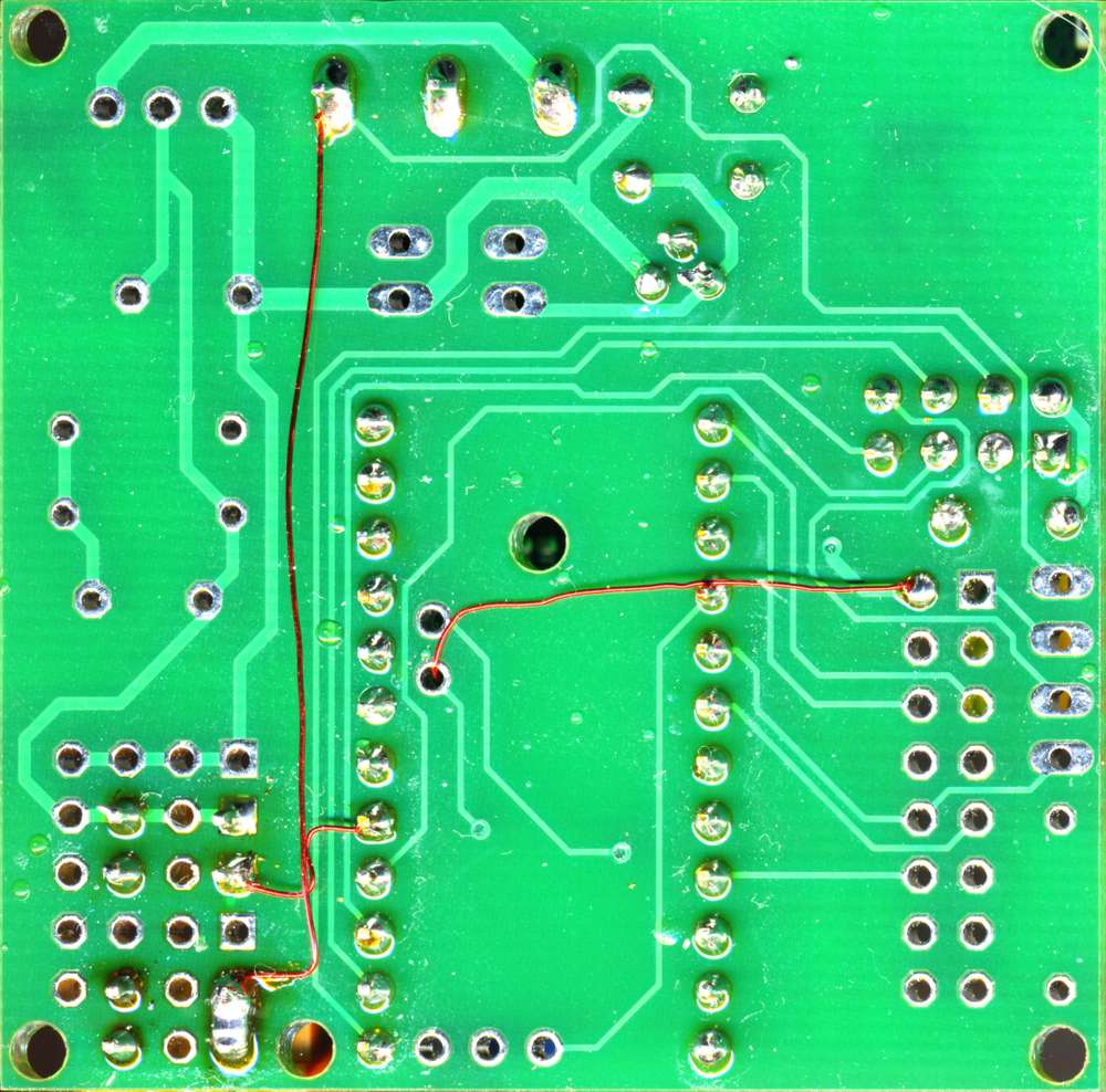
I'm running out of NRF modules and out of ideas. I attach some pictures that show my module and really hope that you have some new ideas. Did I mess up the AREF?
Ah, what? The forum doesn't allow uploading source code? Well, then as code block:
/**
 * The MySensors Arduino library handles the wireless radio link and protocol
 * between your home built sensors/actuators and HA controller of choice.
 * The sensors forms a self healing radio network with optional repeaters. Each
 * repeater and gateway builds a routing tables in EEPROM which keeps track of the
 * network topology allowing messages to be routed to nodes.
 *
 *******************************
 *
 * DESCRIPTION
 * This sketch reads wind speed information from an Adafruit Wind Speed Sensor 1733
 *
 * Specifications
 *
 *  Output: 0.4V to 2V
 *  Testing Range: 0.5m/s to 50m/s
 *  Start wind speed: 0.2 m/s
 *  Resolution: 0.1m/s
 *  Accuracy: Worst case 1 meter/s
 *  Max Wind Speed: 70m/s
 *  Connector details: Pin 1 - Power (brown wire),
 *                     Pin 2 - Ground (black wire),
 *                     Pin 3 - Signal (blue wire),
 *                     Pin 4 not connected
 *
 */

// Enable debug prints
#undef MY_DEBUG

// Enable and select radio type attached
#define MY_RADIO_NRF24

// Enabled repeater feature for this node
#define MY_REPEATER_FEATURE

/**
 * @def MY_NODE_ID
 * @brief Node id defaults to AUTO (tries to fetch id from controller).
 */
#define MY_NODE_ID 105

/**
 * @def MY_PARENT_NODE_ID
 * @brief Node parent defaults to AUTO (tries to find a parent automatically).
 */
#define MY_PARENT_NODE_ID 0

#include <MySensors.h>
#include <limits.h>

// (External) Reference voltage in Volts
// We use the external 3.3V because it's closer to the 2V maximum of the sensor.
// This way we loose less of the ADC range
#define U_REF_V (3.3)

// Set this to the pin you connected the DHT's data pin to
#define WIND_ANLOG_PIN A0

#define SECOND (1000)  // seconds to milliseconds

// Sleep time between sensor updates (in milliseconds)
static const uint64_t UPDATE_INTERVAL_MS = 10 * SECOND;

// Force sending an update of the temperature after n sensor reads, so a controller showing the
// timestamp of the last update doesn't show something like 3 hours in the likely case, that
// the value didn't change since;
// i.e. the sensor would force sending an update every UPDATE_INTERVAL*FORCE_UPDATE_N_READS [ms]
static const uint8_t FORCE_UPDATE_N_READS = 6 * 5;  // each 5 minutes

#define CHILD_ID_WIND 0

#define LSB_TO_VOLT (U_REF_V/1024)   // V/LSB
#define V_MAX_mps   (70)             // Maximum wind speed in m/s
#define U_MIN_V     (0.4)            // Minimum voltage in V
#define U_MAX_V     (2.0)            // Maximum voltage in V
#define SENSOR_PRECISION_MPS (0.1)   // precision of the sensor in m/s

// m=70/(2-0.4)   m/(sV)
// t=-0.4*m       m/s
// v=m*u+t

#define M (V_MAX_mps/(U_MAX_V-U_MIN_V))    //  m/(sV)
#define T (-U_MIN_V*M)                     //  m/s

float lastWindSpeed_mps;
uint8_t noUpdates;

MyMessage msgWindSpeed(CHILD_ID_WIND, V_WIND);

float lsbToWindSpeed(const float lsb)  {
  const float u_V = lsb * LSB_TO_VOLT;
  float speed_mps = M * u_V + T;
  if( speed_mps <0 ) {
    speed_mps = 0;
  }
  return speed_mps;
}

void presentation()
{
  // Send the sketch version information to the gateway
  sendSketchInfo("WindSpeed", "1.1");

  // Register all sensors to gw (they will be created as child devices)
  present(CHILD_ID_WIND, S_WIND);
}


void setup()
{
  analogReference(EXTERNAL);         // use the external reference voltage
  pinMode(WIND_ANLOG_PIN, INPUT);
  lastWindSpeed_mps = -1;
  noUpdates = 0;
}


void loop()
{
  int adcValue = analogRead(WIND_ANLOG_PIN);
  float windSpeed_mps = lsbToWindSpeed(adcValue);


#ifdef MY_DEBUG
  Serial.print("ADC: ");
  Serial.println(adcValue);
  Serial.print("SP1: ");
  Serial.println(windSpeed_mps);
#endif


  if ( abs(lastWindSpeed_mps - windSpeed_mps) >= SENSOR_PRECISION_MPS || noUpdates== FORCE_UPDATE_N_READS ) {
    lastWindSpeed_mps = windSpeed_mps;
    noUpdates = 0;

    send(msgWindSpeed.set(windSpeed_mps, 1));

#ifdef MY_DEBUG
    Serial.print("SP2: ");
    Serial.println(windSpeed_mps);
#endif
  }
  else {
    ++noUpdates;
  }

  // Sleep for a while to save energy
  sleep(UPDATE_INTERVAL_MS);
}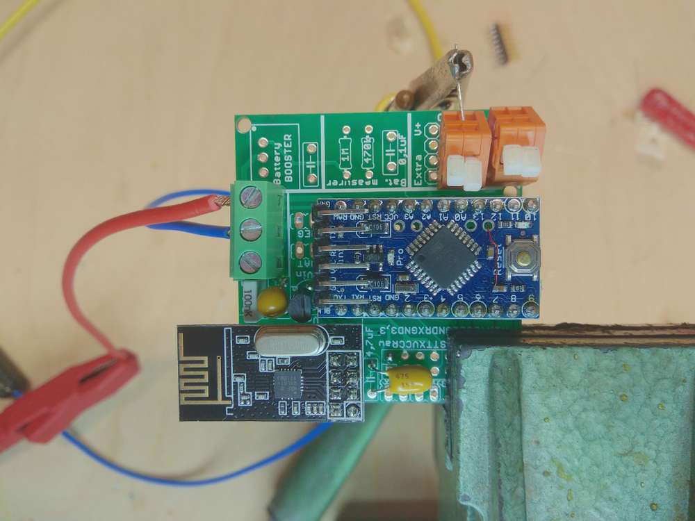
Here you can see a video with the rising power consumption:
https://youtu.be/7o4FYRTkRLANext days I'll remove the 3.3V modification and try it with the default. The extra bit resolution is not really necessary. But I can't imagine that's the reason.
-
Hello,
I built the board from scratch and am none the wiser :(
To recap: I have built a mysensors sensor to read the wind speed of an Adafruit Anemometer. That sensor literally burned Nrf24l01+ modules and I have no idea why.
The only special thing about this sensor is that I connected the AREF pin of the Arduino to 3.3V because the Aneometers output is 0.4..2V and I didn't want to waste a ADC bit because of the standard 5V reference voltage. I did this by connecting AREF directly to 3.3V and I let the capacitor from AREF to GND in place.
I connected the new module to a 2 channel lab power supply: 9V to the RAW input (because the Anemometer needs 7 to 12V power supply) with a maximum current of ~100mA. 0.4V to A0 with barely some current flowing to simulate the Anemometer. I powered up the module and everything worked. The module consumed about 23mA which is the value that I expected from earlier tries. Yay!
About 15 minutes later: Communication was broken again. The Arduino LED that indicates SPDIF clock was dark, the Power supply showed >110mA power consumption. Sh*t.
I lowered the Supply voltage to 5V (maybe to cause less damage...) and power cycled the module. It started with 35mA and was working (presentation to the controller and sends wind speed). And then... the consumed current rises! The longer, the faster. I let it run for about 1.5 minutes and the consumed current doubled to more than 60mA.
I'm running out of NRF modules and out of ideas. I attach some pictures that show my module and really hope that you have some new ideas. Did I mess up the AREF?
Ah, what? The forum doesn't allow uploading source code? Well, then as code block:
/**
 * The MySensors Arduino library handles the wireless radio link and protocol
 * between your home built sensors/actuators and HA controller of choice.
 * The sensors forms a self healing radio network with optional repeaters. Each
 * repeater and gateway builds a routing tables in EEPROM which keeps track of the
 * network topology allowing messages to be routed to nodes.
 *
 *******************************
 *
 * DESCRIPTION
 * This sketch reads wind speed information from an Adafruit Wind Speed Sensor 1733
 *
 * Specifications
 *
 *  Output: 0.4V to 2V
 *  Testing Range: 0.5m/s to 50m/s
 *  Start wind speed: 0.2 m/s
 *  Resolution: 0.1m/s
 *  Accuracy: Worst case 1 meter/s
 *  Max Wind Speed: 70m/s
 *  Connector details: Pin 1 - Power (brown wire),
 *                     Pin 2 - Ground (black wire),
 *                     Pin 3 - Signal (blue wire),
 *                     Pin 4 not connected
 *
 */

// Enable debug prints
#undef MY_DEBUG

// Enable and select radio type attached
#define MY_RADIO_NRF24

// Enabled repeater feature for this node
#define MY_REPEATER_FEATURE

/**
 * @def MY_NODE_ID
 * @brief Node id defaults to AUTO (tries to fetch id from controller).
 */
#define MY_NODE_ID 105

/**
 * @def MY_PARENT_NODE_ID
 * @brief Node parent defaults to AUTO (tries to find a parent automatically).
 */
#define MY_PARENT_NODE_ID 0

#include <MySensors.h>
#include <limits.h>

// (External) Reference voltage in Volts
// We use the external 3.3V because it's closer to the 2V maximum of the sensor.
// This way we loose less of the ADC range
#define U_REF_V (3.3)

// Set this to the pin you connected the DHT's data pin to
#define WIND_ANLOG_PIN A0

#define SECOND (1000)  // seconds to milliseconds

// Sleep time between sensor updates (in milliseconds)
static const uint64_t UPDATE_INTERVAL_MS = 10 * SECOND;

// Force sending an update of the temperature after n sensor reads, so a controller showing the
// timestamp of the last update doesn't show something like 3 hours in the likely case, that
// the value didn't change since;
// i.e. the sensor would force sending an update every UPDATE_INTERVAL*FORCE_UPDATE_N_READS [ms]
static const uint8_t FORCE_UPDATE_N_READS = 6 * 5;  // each 5 minutes

#define CHILD_ID_WIND 0

#define LSB_TO_VOLT (U_REF_V/1024)   // V/LSB
#define V_MAX_mps   (70)             // Maximum wind speed in m/s
#define U_MIN_V     (0.4)            // Minimum voltage in V
#define U_MAX_V     (2.0)            // Maximum voltage in V
#define SENSOR_PRECISION_MPS (0.1)   // precision of the sensor in m/s

// m=70/(2-0.4)   m/(sV)
// t=-0.4*m       m/s
// v=m*u+t

#define M (V_MAX_mps/(U_MAX_V-U_MIN_V))    //  m/(sV)
#define T (-U_MIN_V*M)                     //  m/s

float lastWindSpeed_mps;
uint8_t noUpdates;

MyMessage msgWindSpeed(CHILD_ID_WIND, V_WIND);

float lsbToWindSpeed(const float lsb)  {
  const float u_V = lsb * LSB_TO_VOLT;
  float speed_mps = M * u_V + T;
  if( speed_mps <0 ) {
    speed_mps = 0;
  }
  return speed_mps;
}

void presentation()
{
  // Send the sketch version information to the gateway
  sendSketchInfo("WindSpeed", "1.1");

  // Register all sensors to gw (they will be created as child devices)
  present(CHILD_ID_WIND, S_WIND);
}


void setup()
{
  analogReference(EXTERNAL);         // use the external reference voltage
  pinMode(WIND_ANLOG_PIN, INPUT);
  lastWindSpeed_mps = -1;
  noUpdates = 0;
}


void loop()
{
  int adcValue = analogRead(WIND_ANLOG_PIN);
  float windSpeed_mps = lsbToWindSpeed(adcValue);


#ifdef MY_DEBUG
  Serial.print("ADC: ");
  Serial.println(adcValue);
  Serial.print("SP1: ");
  Serial.println(windSpeed_mps);
#endif


  if ( abs(lastWindSpeed_mps - windSpeed_mps) >= SENSOR_PRECISION_MPS || noUpdates== FORCE_UPDATE_N_READS ) {
    lastWindSpeed_mps = windSpeed_mps;
    noUpdates = 0;

    send(msgWindSpeed.set(windSpeed_mps, 1));

#ifdef MY_DEBUG
    Serial.print("SP2: ");
    Serial.println(windSpeed_mps);
#endif
  }
  else {
    ++noUpdates;
  }

  // Sleep for a while to save energy
  sleep(UPDATE_INTERVAL_MS);
}
Here you can see a video with the rising power consumption:
https://youtu.be/7o4FYRTkRLANext days I'll remove the 3.3V modification and try it with the default. The extra bit resolution is not really necessary. But I can't imagine that's the reason.
-
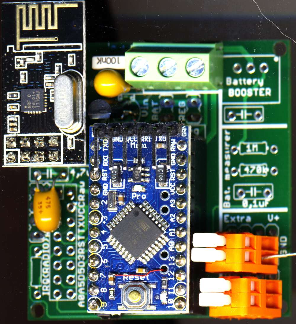
The Culprit seems to be the yellow capacitor next to the gray 100nF Capacitor. Should be 10uF, I think. If I cool that one with ice spray, power consumption normalizes immediately.
It seems to be really hard to buy high quality components, even at shops that have a good name.
-
The Culprit seems to be the yellow capacitor next to the gray 100nF Capacitor. Should be 10uF, I think. If I cool that one with ice spray, power consumption normalizes immediately.
It seems to be really hard to buy high quality components, even at shops that have a good name.
-
The Culprit seems to be the yellow capacitor next to the gray 100nF Capacitor. Should be 10uF, I think. If I cool that one with ice spray, power consumption normalizes immediately.
It seems to be really hard to buy high quality components, even at shops that have a good name.
@The-Grue
That yellow capacitor looks like a tantalum capacitor (hard to be certain from the top view, but I guess it is the same type as the other yellow one on the board on which you can read the printing). In the case of it actually being a tantalum cap, you may have by accident installed it in the wrong orientation. Tantalum caps have a polarity and if wrongly applied (i.e. reverse polarity/voltage) it will typically show a gradual increase in leakage current - what appears to match with your description.So that is probably one of the reasons why you see tantalum caps being used less nowadays as it is easy to put them in the wrong way and hard to troubleshoot afterwards (visually quickly overlooked).
-
@The-Grue
That yellow capacitor looks like a tantalum capacitor (hard to be certain from the top view, but I guess it is the same type as the other yellow one on the board on which you can read the printing). In the case of it actually being a tantalum cap, you may have by accident installed it in the wrong orientation. Tantalum caps have a polarity and if wrongly applied (i.e. reverse polarity/voltage) it will typically show a gradual increase in leakage current - what appears to match with your description.So that is probably one of the reasons why you see tantalum caps being used less nowadays as it is easy to put them in the wrong way and hard to troubleshoot afterwards (visually quickly overlooked).
Hello @Technovation,
as embarrassing as it is: you are completely right :blush: . For more than 30 years, I've either used elkos (where I know they have a polarity) or ceramic capacitors (which don't have one) or used the correct polarity by accident and was completely baffled when I learned that tantalum capacitors have a polarity. It doesn't help that the only indication is so non-descript...
Well, you never stop learning. I'm looking forward to much more stable mysensors :)
And I apologize for blaming the NRF24 modules and the shops for my ignorance.
-
Hello @Technovation,
as embarrassing as it is: you are completely right :blush: . For more than 30 years, I've either used elkos (where I know they have a polarity) or ceramic capacitors (which don't have one) or used the correct polarity by accident and was completely baffled when I learned that tantalum capacitors have a polarity. It doesn't help that the only indication is so non-descript...
Well, you never stop learning. I'm looking forward to much more stable mysensors :)
And I apologize for blaming the NRF24 modules and the shops for my ignorance.
@The-Grue: Don't be embarrassed by it...pretty sure you are not the first one that fell for this trap and certainly not the last one. Hopefully also other readers on the forum can benefit from your (bad) experience in this way.
Thanks for reporting back and good to hear that some of your trust has returned towards the nrf24 and your part shops with a "good name" :slightly_smiling_face: .
Hello! It looks like you're interested in this conversation, but you don't have an account yet.
Getting fed up of having to scroll through the same posts each visit? When you register for an account, you'll always come back to exactly where you were before, and choose to be notified of new replies (either via email, or push notification). You'll also be able to save bookmarks and upvote posts to show your appreciation to other community members.
With your input, this post could be even better 💗
Register Login