RFM69HW & ATC not working
-
Hi,
I'm hoping someone can help me with ATC mode on my RFM69HW/Arduino Pro Mini nodes.
I've enabled it per the example sketch RFM69_RFM95_ATC_SignalReport.ino.I've updated the node & gateway to use the new RFM69 driver.
It doesn't seem to adjust the transmit power on my node and I get a TSF error as well.
A couple example debug outputs:BME280 - Sending the new humidity to the gateway. 55791 TSF:MSG:SEND,4-4-0-0,s=1,c=1,t=1,pt=7,l=5,sg=0,ft=0,st=OK:53.11 Uplink Qlty: 0, Xmit Level (dBm): 107, Xmit Level (%): 140 Xmit RSSI: -46, Recv RSSI: -54, Xmit SNR: -256, Recv SNR: -256 55805 TSF:MSG:READ,92-1-4,s=2,c=1,t=4,pt=0,l=6,sg=0:102.05 55816 !TSF:MSG:LEN=26,EXP=13 State: ST_SLEEP Uplink Qlty: 0, Xmit Level (dBm): 11, Xmit Level (%): 108 Xmit RSSI: -46, Recv RSSI: -53, Xmit SNR: -256, Recv SNR: -256 56082 TSF:MSG:READ,92-2-4,s=2,c=1,t=4,pt=0,l=6,sg=0:102.05 56094 !TSF:MSG:LEN=32,EXP=13 56096 TSF:MSG:READ,92-2-4,s=2,c=1,t=4,pt=0,l=6,sg=0:102.05 56102 !TSF:MSG:LEN=26,EXP=13 State: ST_SLEEPYou can see that the Xmit levels don't make sense.
The Xmit RSSI should be moving towards -70 dBm but never really changes.Here's the macros in the node's code:
// if you uncomment this, you can get test and debug updates about everything the sensor is doing by using the serial monitor tool.
#define MY_DEBUG

// Enable and select radio type attached
//#define MY_RADIO_RF24                            // A 2.4Ghz transmitter and receiver, often used with MySensors.
// #define MY_RF24_PA_LEVEL RF24_PA_MIN              // This sets a low-power mode for the radio. Useful if you use the version with the bigger antenna, but don't want to power that from a separate power source. It can also fix problems with fake Chinese versions of the radio.
#define MY_RADIO_RFM69                        // possible 434, 868, 915Mhz transmitter and reveiver.
#define MY_RFM69_NEW_DRIVER                   // ATC on RFM69 works only with the new driver (not compatible with old=default driver)
#define MY_IS_RFM69HW                         // high power version of radio
#define MY_RFM69_FREQUENCY  RFM69_915MHZ
#define MY_RFM69_ATC_TARGET_RSSI_DBM (-70)    // target RSSI -70dBm
#define MY_RFM69_MAX_POWER_LEVEL_DBM 10       // max. TX power 10dBm = 10mW

// Do you want this sensor to also be a repeater?
// #define MY_REPEATER_FEATURE                    // Just remove the two slashes at the beginning of this line to also enable this sensor to act as a repeater for other sensors. If this node is on battery power, you probably shouldn't enable this.

// Are you using this sensor on battery power?
#define BATTERY_POWERED

// Would you like to report humidity?
#define REPORT_HUMIDITY

// LIBRARIES
#include <SPI.h>                                  // A communication backbone, the Serial Peripheral Interface.
#include <MySensors.h>                            // The MySensors library. Hurray!
#include <Wire.h>                                 // Enables the Wire communication protocol.
#include <BME280_MOD-1022.h>                      // Bosch BME280 Embedded Adventures MOD-1022 weather multi-sensor Arduino code, written originally by Embedded Adventures. https://github.com/embeddedadventures/BME280
and later, in the loop()
#ifdef REPORT_HUMIDITY
      // Send humidity
      if (COMPARE_HUM == 1 && fabs(humidity - lastHumidity) < humThreshold) { // is the humidity difference bigger than the threshold?
//        Serial.print(humidity - lastHumidity);
//        Serial.println("- BME280 - Humidity difference too small, so not sending the new measurement to the gateway.");
      } else {
        Serial.println("BME280 - Sending the new humidity to the gateway.");
        send(humidityMsg.set(humidity, 2));
        lastHumidity = humidity; // Save new humidity to be able to compare in the next round.
      }
#endif
      // Send pressure
      if (COMPARE_PRES == 1 && fabs(pressure - lastPressure) < presThreshold) { // is the pressure difference bigger than the threshold?
//        Serial.print(pressure - lastPressure);
//        Serial.println("- BME280 - Pressure difference too small, so not sending the new measurement to the gateway.");
      } else {
        Serial.println("BME280 - Sending the new pressure to the gateway.");
        send(pressureMsg.set(pressure, 2));
        lastPressure = pressure; // Save new pressure to be able to compare in the next round.
      }

      ReportRfPower();
      state = ST_SLEEP;
      break;
and the report of ATC values:
void ReportRfPower()
{
  Serial.print("Uplink Qlty: ");  Serial.print(transportGetSignalReport(SR_UPLINK_QUALITY));
  Serial.print(", Xmit Level (dBm): ");  Serial.print(transportGetSignalReport(SR_TX_POWER_LEVEL));
  Serial.print(", Xmit Level (%): ");  Serial.println(transportGetSignalReport(SR_TX_POWER_PERCENT));

  Serial.print("Xmit RSSI: ");  Serial.print(transportGetSignalReport(SR_TX_RSSI));
  Serial.print(", Recv RSSI: ");  Serial.print(transportGetSignalReport(SR_RX_RSSI));
  Serial.print(", Xmit SNR: ");  Serial.print(transportGetSignalReport(SR_TX_SNR));
  Serial.print(", Recv SNR: ");  Serial.println(transportGetSignalReport(SR_RX_SNR));
}
Any ideas?
-
I've more information to share.
Seems I was running out of memory, when I turned off debug, which freed up some room, I started to get more reasonable results.
Uplink Qlty: 0, Xmit Level (dBm): -2, Xmit Level (%): 0
Xmit RSSI: -45, Recv RSSI: -39
Wondering if this is as low as it can go?
Looking at the datasheet,
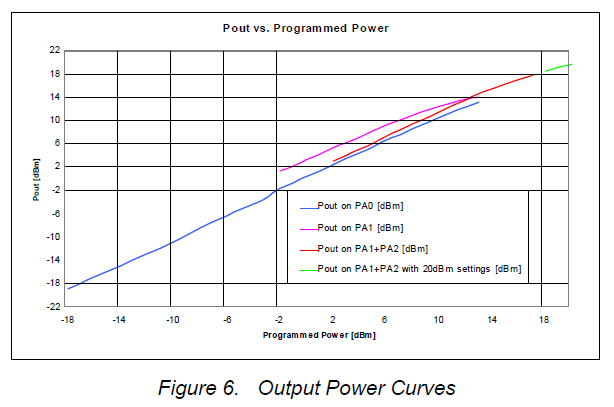
PA1 and PA2 combined on pin PA_BOOST: +2 to +17 dBm
and
PA1+PA2 on PA_BOOST with high output power +20dBm settings (see 3.3.7): +5 to +20 dBmI don't know what power level is selected when we enable #define MY_IS_RFM69HW
Can we simply run it as a low power RFM69 by commenting out the #define?
-
Documenting what I've found in the library code for the community.
When using #define MY_IS_RFM69HW:
The driver enables PA1 and PA2 and disables PA0 power amps. It automatically selects the right combination of PA1 and PA2 to achieve the target power level.
Power range is -2 to +20 dBmWhen NOT using #define MY_IS_RFM69HW:
Then only PA0 is enabled.
PA0 is identical between the RFM69W and RFM69HW.
Power range is -18 to +13 dBm
Basically, your RFM69HW operates as an RFM69W.Also, when using the new RFM69 driver, ATC mode is on by default, unless you explicitly turn it off using macro #define MY_RFM69_ATC_MODE_DISABLED
The default ATC target RSSI level is -80 dBm which you can change using #define MY_RFM69_ATC_TARGET_RSSI_DBMCheers
-
@KevinT
well, that's strange. Because lot of people experienced communication issues when missing the MY_IS_RFM69HW with RFM69H, very weak range or no comm. It's not about the library, it's about the module itself and its hardware implementation.of course MY_RADIO_RFM69 is mandatory :)
do you get a usable range when using RFM69H as a RFM69W? As good as a RFM69W??
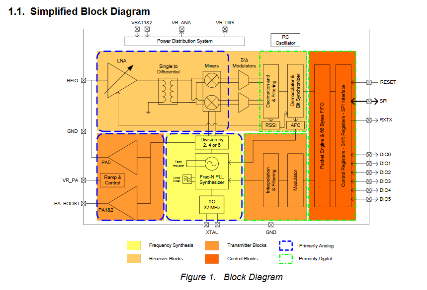
Here you can see PA0 is connected to RFIO pin which also handles the LNA, and PA1/2 to PA_BOOST pin

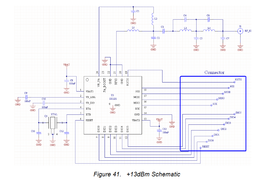
Here is how RFM69W works, it's just connected to RFIO, for PA0 and LNA

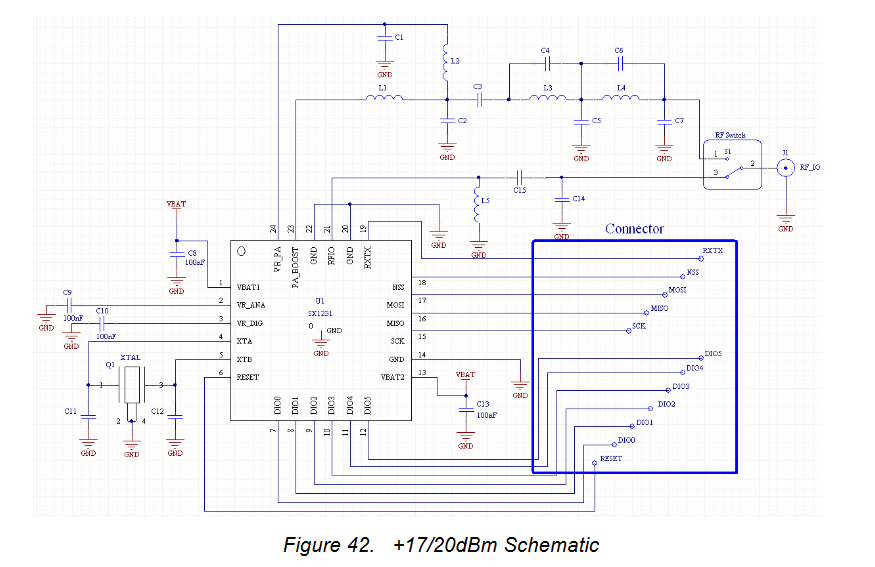
And, this is how RFM69H works. There is a RF Switch, which is controlled by the rxtx pin. So, in TX mode it uses PA_BOOST (PA1/2), and in RX mode it uses RFIO for LNA.

Note: all the tuning passives on both modules, on TX path, for tuning filtering etc.
So if you don't use the MY_IS_RFM69HW with a RFM69H, to only use PA0, then I doubt you can get same range as RFM69W.
Finally, I woud usually recommand to use MY_IS_RFM69HW if using RFM69HW/HCW and let ATC feature handles power level, or use a RFM69W/CW (with ATC too of course)
Here a few links which also explain this, but you can find more infos aboutthis on internet:
https://andrehessling.de/2015/02/07/figuring-out-the-power-level-settings-of-hoperfs-rfm69-hwhcw-modules/
https://lowpowerlab.com/forum/rf-range-antennas-rfm69-library/standardise-mote-configuration-using-rfm69hw-only/ -
@KevinT
well, that's strange. Because lot of people experienced communication issues when missing the MY_IS_RFM69HW with RFM69H, very weak range or no comm. It's not about the library, it's about the module itself and its hardware implementation.of course MY_RADIO_RFM69 is mandatory :)
do you get a usable range when using RFM69H as a RFM69W? As good as a RFM69W??
Here you can see PA0 is connected to RFIO pin which also handles the LNA, and PA1/2 to PA_BOOST pin

Here is how RFM69W works, it's just connected to RFIO, for PA0 and LNA

And, this is how RFM69H works. There is a RF Switch, which is controlled by the rxtx pin. So, in TX mode it uses PA_BOOST (PA1/2), and in RX mode it uses RFIO for LNA.

Note: all the tuning passives on both modules, on TX path, for tuning filtering etc.
So if you don't use the MY_IS_RFM69HW with a RFM69H, to only use PA0, then I doubt you can get same range as RFM69W.
Finally, I woud usually recommand to use MY_IS_RFM69HW if using RFM69HW/HCW and let ATC feature handles power level, or use a RFM69W/CW (with ATC too of course)
Here a few links which also explain this, but you can find more infos aboutthis on internet:
https://andrehessling.de/2015/02/07/figuring-out-the-power-level-settings-of-hoperfs-rfm69-hwhcw-modules/
https://lowpowerlab.com/forum/rf-range-antennas-rfm69-library/standardise-mote-configuration-using-rfm69hw-only/@scalz
This is my first attempt at using the lower power PA0. I am getting an RSSI of -75 with the radios about 5m apart and the radio using 10 dBm to achieve this. Quite disappointing. I was expecting the transmit power to be much lower, since in High Power mode I was getting an RSSI of -45 with transmit power of -2 dBm.
I thought that perhaps the radio was reporting the wrong transmit power, or that the library was not interpreting it correctly. I expected results similar to the data sheet.

But you say this is a common problem!
I was planning on standardising on the high power radio for all my nodes, but now I see I will have to switch to the RFM69W for many of them.Thanks very much for taking the time to bring me up to speed, its greatly appreciated.
-
@KevinT
Indeed, that's not very good range.
As a rough comparison (because it can depend on others factors), with rfm69cw and a short range of 10-12m, with 2 bricks walls obstacles, I set ATC RSSI target= -87, and power level is autoadjusted to -11So, regarding RFM69, for shorter ranges, RFM69W/CW can save power, and for others distances, RFM69H is better choice
I'm glad if I helped you :)
-
@KevinT
yes in general subghz radios have better range than 2.4ghz.
I might have farther nodes but for example, I have one rfm69cw at 55m from the GW and it's ok, with many obstacles on the path (7x rock walls, a part of the roof is metallic, metallic doors etc).
This depends on many factors of course
