Controlling Blinds.com RF Dooya Motors with Arduino and Vera


  • @petewill I looked at the Leviton controller - but I am in Australia, and they don't make an Australian version (for some reason, Z-Wave in Australia is on a different frequency).
    And the fans I am using are Hunter Pacific fans made by an Australian company, and that is probably why the remote works on a different frequency. I believe Hunter and Hunter Pacific are different companies - just in case anyone gets them confused.


  • Admin

    @CalvinAndHobbes said:

    I believe Hunter and Hunter Pacific are different companies

    Yes, thanks for clarifying. I was thinking they were the same.

    Too many frequencies to worry about... I wish z-wave was all the same. It would simpler...


  • I contacted the manufacturer, and they confirmed the protocol is a proprietary one, but they suggested I hack the remote directly, and even offered to send me some remotes to play with, so I am going to go down that route. The remote is very easy to hack too.


  • Admin

    @CalvinAndHobbes said:

    but they suggested I hack the remote directly, and even offered to send me some remotes to play with

    Wow, that is awesome! Good work!


  • Hero Member

    @CalvinAndHobbes, @petewill ,

    I have a similar challenge, to automate some fans that I have in my house. I didn't have the same luck when contacting the manufacturer. I tried to hack the radio messages using both 433Mhz and 315Mhz sniffers, but they must use a different radio, or I did something wrong.

    It is relatively easy to hack my remotes and insert an Arduino + radio, however I'm thinking in other aspects before start --- Such as replacing the battery of the remote (currently a single CR2032 cell) , as it will have to be "always on" in order to listen to the gateway.

    I'm also think in do a 'bi-way' interface, so instead only listem gw and 'press buttons' in the remote, the inserted arduino would also sense if any button is pressed in the remote and report it back to GW.

    And my remotes uses the same key for on AND off. So unless I put another sensor nearby (or in) the fans, the gw will never 'be sure' if the fan is on or off...

    Just some thoughts about the topic...


  • Admin

    @rvendrame said:

    Just some thoughts about the topic...

    Thanks. I agree, there doesn't seem to be a perfect solution. For my blinds we rarely use the remotes that came with them. That way we don't need to worry about the status being incorrect. I have modified phones placed around the house we use as control panels as well as apps on our phones. But, for the most part the blinds are all controlled automatically by the light level outside. A ceiling fan would be different though I'd imagine.


  • Hi to everyone! Im very (I mean VERY) new at this, and Im far to be a programer or an specialist, Im just an enthusiastic end user willing to do all of you experts do!

    I have the same problem as Pete had, I have some dooya motors in my blinds and I want to integrate them to my smarthome system. This blinds are controlled by a remote control with 3 buttons, up – down – stop, and they are suppose to be RF, they have awesome range btw (see pics).

    IMG_3770.JPG
    IMG_3072.JPG IMG_3071.JPG IMG_3771.JPG

    First I tried the RC-Switch to sniff the RF code, but the program return nothing, just blank, that’s why I came to this, wich I would like to thank Pete for giving a light at the end of the tunel! (which Im still in).

    I did all the process to sniff the signal of the remotes, and this is what I got and traduced to binary:

    RFSalaBO.PNG

    Not the same wave structure (squared) but I hope it has nothing to do.

    Now Im in the process of testing this code just with the Arduino, but it doesn’t work! I followed the code Pete uploaded and change the highlighted parts with my code, please let me know if I did ok, this are what I changed:

    This first part, I used the first 28 bits of my signal, which is the same in the 3 comands:
    codepart1.PNG
    Here, I used the last 8 bits for each comand:
    codepart2.PNG

    Any clues what I might be doing wrong?

    Just in case, Im using an Arduino UNO, and I connected it this way:
    IMG_3772.JPG
    IMG_3775.JPG
    IMG_3774.JPG

    Thanks in advance!


  • @frantona Could you post your entire sketch? Did you measure the signal timing?


  • @Dwalt said:

    @frantona Could you post your entire sketch? Did you measure the signal timing?

    Hi! Thanks for your answer. Nope, I didnt measured the signal timing. I missed it. How should I do it?

    I will paste the full code this night when I arrive home, Im using the same one Pete posted few messages back.

    Thanks a lot!


  • @frantona Here is a tutorial on figuring out the timing. Pete's sketch uses the timing (length) for the high and low of both the ones and zeros (lines 35-38).

    Have you tried this with the RCSwitch or Remoteswitch libraries? They take all the guesswork out of sniffing signals although they don't work for all transmitters. [Edit: nevermind, i reread your post where you did say you tried RCSwitch].


  • What a great thread, thanks @petewill for all of the info. I can't wait to give this a try.
    After reading through all of this, am I correct in assuming that using the slider control (or programming a controller to open the shade to a certain %) has not been achieved?
    I was thinking about this a bit, and thought about perhaps using a few cheap magnetic door sensors along the edge of the window at different positions. You could then attach a small neodymium magnet to the back of the bottom edge of the shade that passes by the door sensors. Each of those door sensors could report a value back to the controller, indicating its position (ie 0,25,50,75,100), and if the MySensors node receives a slider value from the controller, you could round to the closest value, and raise/lower the shade until that value is achieved.
    I'm a complete MySensors/HA/Vera noob, so please excuse my ignorance if this is a ridiculous solution to a simple issue. 😁


  • Admin

    @Mike1082 You are correct. Slider control hasn't been achieved. I have thought about doing something like this but I haven't had too much of a need for it in the 1+ years I have had the blinds. Usually up or down is all I want. 🙂

    The one problem I could see with doing this is you will need some sort of device placed at the blind. Currently all you need is power (battery or hard wired) and this works. If you want to report values back, you will need another sensor there. Not a deal breaker but not ideal. Also, you would need a way to confirm that it stopped (in case the signal didn't get received from the blind). If you are seriously considering doing this you may want to look into using a reed switch and mounting it on the spindle that turns when the blinds go up/down. That way you get a cleaner install with more frequent updates.

    I'd love to see it if you end up doing it. It would be a fun project!


  • Hero Member

    @petewill
    Nice work!

    What kind of battery is powering the blinds.com motor and its receiver? From looking at your video, it appears the blinds.com receiver is constantly listening, and having a receiver constantly listening 24/7 all the time can take quite a lot of power (or, at least it would if it were using an NRF24L01+ or an RFM69, although I of course realize it isn't using either one of those).

    Blinds.com says it can take a refillable "wand" that gives 12 volts. So, would that be 8x D-cell batteries?

    Do you find that you need to change the battery in the receiver often?

    Just trying to get a feel for what it would take to be listening 24/7.


  • Admin

    @NeverDie Thanks! It is powered by 8 AA batteries in the battery wand. I actually hardwired mine though. I was able to get power to all my windows fairly easily (although my wife would disagree). So, unfortunately I have no idea how long they last. I feel like I remember people reporting about a year but I can't say where I remember that from.


  • @frantona

    Your code has an error in the 'action' section of the sketch.

    if(a==1){
              action = 0b0001000;  //code for up
    

    It is missing a digit or bit. It should read:

    if(a==1){
              action = 0b00010001; //code for up
    

    I also think you mixed the 'down' with 'stop' actions. Try this:

    if(a==1){
              action = 0b00010001; //code for up
              action2 = 0b00001110;
            }
            else if (a==2){
              action = 0b00010011; //code for down
              action2 = 0b00001100;
            }
            else if (a==3){
              action = 0b00010101; //code for stop
              action2 = 0b00000101;   
         }


  • Hardware Contributor

    I hope its ok that I use this thread for my question, because the topic 'kinda fits:
    does anyone know a (cheap) way to add a motor (that could be controlled by mysensor) to existing blinds? In theory you would only need a small motor I guess, but I am unsure how to connect that to the blinds..


  • Hello,

    there is an other way to control your shutters.

    Dooya shutter control

    It´s itegrated in FHEM. There are also the decryption at the shuttersignal. All 40 Bit and the explain to the 40 Bit.

    sorry for my weak english.

    Jarnsen


  • Hi @petewill , I've been trying to implement a similar setup to this for the past few days, however I've unfortunately been unsuccessful with the RF sniffing step. I've tried multiple RF receivers (I have a 10-pk), multiple resistors, and multiple audio cables, yet the feedback from Audacity appears the same whether I'm not doing anything or spamming the remote buttons:

    0_1463936657162_audacity1.jpg

    Top is with nothing being pressed, bottom is with hitting buttons on the remote. Might you know of any other possible troubleshooting options I could do? If it helps, below is the remote from blinds.com:

    0_1463936739804_blindsdotcom remote.jpg

    Any advice would be appreciated. Thanks!


  • Admin

    @Rantlers Sorry for the delayed reply... busy day back at work.

    Hmm. Did you zoom in on the audacity waveform? I had to zoom way in. If that doesn't show anything it may be that the remotes are at a different frequency now. That looks different than mine. Is there any indication which frequency the remote is on?

    Also, I was able to actually hear the signal on my speakers when I played it back. It sounded like high pitched digital noise. Do you hear anything like that?


  • @petewill Hi Pete, thanks for the response, no worries on the delay! I zoomed in every time I created a new recording, but I could never find a distinguishing pattern like the ones you had. Funny, I did suspect that the frequency from the remote could be different so I have a 10pk of 315mhz tx/rx coming in tomorrow. I'll be rather embarrassed if its as simple as that, but pleased at the same time!

    I listened to the playback in your youtube video a few times and the strange thing is it almost sounds like I'm getting static and digital noise throughout the entire recordings, regardless of whether I'm pressing buttons on the remote or not. I honestly don't know of anything that would be constantly spitting out a 433mhz signal though.

    I'll post an update after I get a chance to try the new receivers.


  • Admin

    @Rantlers Yeah, see if you can find what frequency that remote is communicating on. There must be some specs some where on the remote.


  • @petewill Checking back in, have good news & bad news...

    Bad News: No go on the 315mHz receivers. But that's because...

    Good News: I did some research on the remote since you said you didn't recognize it and was able to find the users manual online:

    http://www.automatedshadeinc.com/files/controls-hunterdouglas/powerplatinum_remote_guide_5110540054_0912.pdf

    According to this the RF signal is 2.4ghz (last page of the pdf). However, that being said, am I now SOL in replicating the RF sniffing step with your setup? The only 2.4ghz transceiver I was able to find is this one:

    http://www.amazon.com/Addicore-nRF24L01-Transceiver-Antistatic-Compatible/dp/B00E594ZX0/ref=sr_1_sc_1?s=pc&ie=UTF8&qid=1464286496&sr=1-1-spell&keywords=2.4ghz+transciever+arduino


  • Admin

    @Rantlers Dang! That's too bad. Are the blinds blinds.com brand or Hunter Douglas? I just want to make sure they didn't use a similar remote style but change the frequency.

    The NRF24 is what most of use for these projects so it might not be bad to order some to test. I'm not an expert on radio though so it may not be as easy to "sniff" the signal. I know @Yveaux has built a sniffer but that may only work for the MySensors network. Sorry I can't be more help!


  • Mod

    @petewill said:

    that may only work for the MySensors network

    It will only work for nRF24L01+ chips. It isn't limited to MySensors.


  • Are you sure you have the economy shades? Ive noticed they have disappeared from Blinds.com, or at least I don't see them anymore.


  • @jfeger said:

    Are you sure you have the economy shades? Ive noticed they have disappeared from Blinds.com, or at least I don't see them anymore.

    I just confirmed with Blinds.com online chat that the economy blinds aren't available anymore, or at least for now. They stated there was a defect in the motors, so they had to pull the product and work on a redesign. No timeline on a release.


  • Thanks!!! this was such a great help in getting my dooya blinds from aliexpress working over network.

    I couldn't get the test code above to work and my sequence was 40 bits, so i modified the code quite a bit and made it much more efficient. Here is the code if anyone needs to test their code on arduino.

    //Define Variables
    #define SEND_DATA 4 //Data pin for RF Transmitter
    #define ZERO_HIGH 363 //Delay for the high part of a 0 in microseconds
    #define ZERO_LOW 726 //Delay for the low part of a 0 in microseconds
    #define ONE_HIGH 726 //Delay for the high part of a 1 in microseconds
    #define ONE_LOW 363 //Delay for the low part of a 1 in microseconds
    
    void setup() {
      // put your setup code here, to run once:
    Serial.begin(9600);
    
    String code = "1100111101000001000111011011000100010001";  // Change your blinds code here
    Serial.println(code);
    
    Serial.println();
    
    for (int i=0; i <= 10; i++) {
    
      int delayTime;
      for(int k=0;k<40;k++) {                  //Change k max value here (40) is mine
        char code1 = code.charAt(k);
        int highTime;
        int lowTime;
        delayTime = ((int) code1) -48;        // 48 is zero in ASCII, so 48-48 = 0 as a number.
            if (delayTime == 1){
            highTime = ONE_HIGH;
            lowTime = ONE_LOW;
          }
          else {
            highTime = ZERO_HIGH;
            lowTime = ZERO_LOW;
          }
            digitalWrite(SEND_DATA, HIGH);
            delayMicroseconds(highTime);
            digitalWrite(SEND_DATA, LOW);    
            delayMicroseconds(lowTime);
    
      }
      Serial.println();
      Serial.print("Round:");
      Serial.print(i);
      Serial.println();
      delay(50);
    }
    
    
    }
    
    void loop() {
    
    }


  • Please help me,
    My remote is dooya. And sniff code:
    10000011 01000010 01001001 11100001 00110011 pause
    10000011 01000010 01001001 11100001 01010101 up
    10000011 01000010 01001001 11100001 00111100 down

    I had use USB Saleae Analyzer sniff code.

    But not work, 😞

    alt text


  • Mod

    @かいと please do not cross post. If people can help you they will respond. Be patient!


  • Admin

    @かいと The pattern for the control may have changed...? Because you have a recording of the remote I would try to record what you are sending with your transmitter and compare the waveform of the two devices. They should be identical. That is how I ended up figuring out the exact timing needed for my motors.


  • My remote alt text


  • Hi guys,
    I realise that this is quite an old thread, but i found it a useful source of info when looking for a solution for my 433MHz problem, so I thought I'd share some of my findings...

    We have a holiday home in Spain and it has some external 'awnings' that extend over the windows to provide shade from the sun. In Spain these are called Toldos. They operate using tubular motors controlled using 433MHz remote controls – one remote for each awning, three in total. I'd tried all the regular methods to sniff the 433MHz protocol, but none of the standard Arduino libraries would even acknowledge that the remote was sending out any sort of signal. Other remotes, such as garage door openers, PIR detectors etc work fine with my sniffer, so the hardware/software I was using is good.

    I eventually resorted to using my sound card and Audacity software to capture the transmissions from the remote controls and this work surprisingly well (I'd tried every digital approach you can imagine up to this point, including a logic analyser, and was reluctant to try the analogue approach but wish I’d trued it earlier).

    What I discovered is that when I press either the UP or the Down buttons on the remote, it transmits a timing pulse followed by 40 bits of data. At first I thought that this sequence was repeated 8 times, but I eventually realised that one 40-bit code was used for the first 4 repetitions of the data, followed by a different code for the next 4 repetitions. I later realised that whenever one of these buttons is pressed, the initial 40 bit code is transmitted continuously then the other code is transmitted 4 times when the button is released. When the button is pressed quickly I just get the 'Pressed' code 4 times followed by the 'Released' code 4 times.
    The Stop button works slightly differently - only one code is used and this is transmitted at least 4 times and will continue to be transmitted as long as the button is pressed. (in other words, the Stop button has a 'Pressed' code, but not a 'Released' code).

    It's actually the 'Pressed' code for each button that controls the awnings. The 'Released' code doesn't seem to serve any function with my awnings.
    These 'Released' codes really confused me to begin with, as I when I checked two different bursts of data from the same button using Audacity, I was getting different results. This was obviously because on one occasion I’d picked one of the ‘Pressed’ codes to analyse, but on the second occasion I’d inadvertently analysed a ‘Released’ code. At first I’d thought the analogue capture process was unreliable, but then I thought that maybe some sort of rolling code system was being used. I eventually realised what was going on, but not until I'd spent quite a bit of time cursing the remote control and the PC.
    I was able to replicate the transmitted code fairly accuracy using a version of @peashooter's code (thanks!) and this worked well
    I’m repeating the ‘Pressed’ code 4 times and it seems to work very reliably.

    As well as being able to control the awnings using an Arduino/ESP8266 transmitter, I also wanted to be able to use the existing handheld remotes, so to be able to understand the current position of each awning I needed a way of receiving the commands from the remotes and using them to keep track of each individual awning. This bought me back to the original problem of not being able to find a way to listen to the 433MHz messages from the remotes using any of the current Arduino libraries.
    In started delving into the idea of modifying the RC-Switch library, now that I knew the timing characteristics of the signals. At that point I stumbled across this small library:
    https://github.com/bjwelker/Raspi-Rollo

    It has an Arduino sketch that is written to identify the codes that are being transmitted by remote controllers for blinds, so that these codes can then be used to control the blinds using a Raspberry Pi.
    When I ran the Arduino sketch it immediately produced results from my Awning remotes – If only I’d found this earlier!
    The results it gives are in a “Quad Bit” format, but when I modified the code to print out the raw received codes they were identical to the results I’d obtained from Audacity.
    I’m not interested in using a Pi to transmit the codes to the blinds, and this wasn’t needed anyway, as using @peashooter's code I already had a transmission solution. I’m now in the process of fine-tuning the code that tracks each blind’s position based on the commands that are sent from either the hand-held remotes or my transmitter. The position is simply based on time between the start and stop transmissions and the known time that it takes to fully extend each awning.

    The primary reason for wanting to control the awnings is that when it gets windy, I want to be able to automatically retract them. I’m using data from a weather station to monitor the wind speed and if it meets the criteria (very strong winds for a short period, or not quite so strong winds for a slightly longer period, then the awnings will be retracted (assuming that they’re extended of course). I’m also automatically retracting them when it gets dark, as it’s easy to forget to do this and a bit cumbersome to walk around and do all three awnings using the separate hand-held remote controls.
    Here’s some pictures of one of the remotes:
    0_1531672414982_IMG_3613.jpg
    0_1531672435282_IMG_3611.jpg
    0_1531672454575_IMG_3610.jpg
    0_1531672467499_IMG_3609.jpg

    The brand name on the remote is Gaviota and the circuit board says “Designed by D Team” “DC104/105” “V2.1” and “No.DA288”.

    Here are what the awnings look like:

    0_1531672501926_IMG_3631.jpg
    I have no idea what the brand name is on the tubular motors, as they’re hidden inside the mechanism.
    Hopefully this saves someone at least some of the pain that I’ve been through to get to this point.

    Pete.


  • @petewill
    Great guide.
    I stumbled upon this when I realised that my Debel awning was using a Dooya motor and remote.

    I did not use your cool system with the soundcard to sniff the RF codes, but instead used my RTL-SDR usb receiver, since I already had it laying around 😀

    After finding the codes I programmed an Arduino with it and connected it to my OpenHAB installation. Now the awning can be controlled with the OpenHAB app, and my wife just loves it 😀

    Just wanted to point it out for others looking for RF codes for Debel awnings.


  • Admin

    @mortenvinding cool! I looked at a couple of code "sniffers" when I did this but none of them worked. Good to hear progress has been made on that. Should save quite a bit of time.


  • I recognize this is an old post, but I've not found any newer discussion and I have hit a roadblock. I've followed all of the very helpful posts to build a sniffer and decode it as tools like RCSwitch wouldn't work. I even used @PeteKnight 's tip to notice there was a different code sent initially when a button was pressed. I've tried sending both versions, emulating the initial (timing?) signal at the start. I tweaked the high and low delays and I think I've got a rf signal that is extremely close to the one from the remote. Here are the two different sources in audacity for comparison.
    ![0_1598212142451_RemoteInAudacity.JPG](Uploading 100%)

    //Define Variables
    #define GND 3
    #define VCC 4
    #define DATA 5 //Data pin for RF Transmitter
    #define ZERO_HIGH 307 //Delay for the high part of a 0 in microseconds
    #define ZERO_LOW 750 //Delay for the low part of a 0 in microseconds
    #define ONE_HIGH 648 //Delay for the high part of a 1 in microseconds
    #define ONE_LOW 409 //Delay for the low part of a 1 in microseconds
    
    int startUp = 1;
    
    unsigned char standardBits1 = 0b00001111; //integer value of the 28 bit standard sequence referenced above. "0b" prefix is for *******
    unsigned char standardBits2 = 0b01111100;
    unsigned char standardBits3 = 0b01100100;
    unsigned char standardBits4 = 0b00000001;
    unsigned char standardBits5 = 0b00011110;
    
    
    void setup() {
      pinMode(GND,OUTPUT);
      pinMode(VCC,OUTPUT);
      pinMode(DATA,INPUT);
      digitalWrite(GND,LOW);
      digitalWrite(VCC,HIGH);
      
       Serial.begin(9600);
     
    }
    
    void loop() {
     unsigned char i;
          delay(3000);
        if(startUp ==1){
        for(i=0;i<10;i++) {
          delay(1000);
          digitalWrite(DATA, HIGH);
          delayMicroseconds(5000);
          digitalWrite(DATA, LOW);    
          delayMicroseconds(1500);        
    
          eightBits(standardBits1);
          eightBits(standardBits2);
          eightBits(standardBits3);
          eightBits(standardBits4);
          eightBits(standardBits5);
          startUp = 0;
        }
     }
    }
          void eightBits(unsigned char bits){
          
              unsigned char k;
              int delayTime;
              for(k=0;k<8;k++) {
                int highTime;
                int lowTime;
                delayTime = ((bits>>(7-k)) & 1 ? 1 : 0); 
              
                if (delayTime == 1){
                  highTime = ONE_HIGH;
                  lowTime = ONE_LOW;
                }
                else {
                  highTime = ZERO_HIGH;
                  lowTime = ZERO_LOW;
                }
                  digitalWrite(DATA, HIGH);
                  delayMicroseconds(highTime);
                  digitalWrite(DATA, LOW);    
                  delayMicroseconds(lowTime);        
            }
         
    }
    

    Here are all the codes I was able to extract from audacity for one of the blinds.
    Down1: 00001111 01111100 01100100 00000001 00111100
    Up1: 00001111 01111100 01100100 00000001 00011110
    Stop1: 00001111 01111100 01100100 00000001 01010101
    Start1: 00001111 01111100 01100100 00000001 00010001
    Does anyone have an idea of what I might still be missing in getting this work?


  • Admin

    @ssuckow I can't see the image but when I did this I started in small steps. Your first goal is to send a successful signal without all the MySensors code. I just created a standalone program with all my code in the setup so when it ran it would send a raise, stop or lower signal. Once you do that you can integrate it with MySensors much easier. It sounds like you have mostly done this based on your description above but I'm not sure. Also, are you sure the hardware is wired correctly? Is the 433Mhz device is getting enough power to send the signal to the blinds?


  • @ssuckow said in Controlling Blinds.com RF Dooya Motors with Arduino and Vera:

    pinMode(DATA,INPUT);

    Why data pin is input? I think it should be output.


  • @petewill Sorry, it seems I had to use the .jpeg extension instead of .jpg. My code is just trying to move the blinds without any extra code. This image shows the remote signal on the top and the Arduino generated signal on the bottom.
    RemoteInAudacity.JPeG


  • @doteq You are correct. That was a holdover from when I was trying to sniff. I tweaked that and this image shows the updated version as Arduino7. Apparently it worked with it defined as input (as receiver connected to audacity was picking it up), but their was a lot more noise. Now, the signal looks very much like the source remote. However, It still doesn't move the blinds. 😞

    Capture.jpeg


  • From the code it looks like you're switching on the receiver by enabling the gnd and vcc pins with an output of the microcontroller. Do you have additional transistors to do so, or just with the output pins directly? In the last case I would recommend to connect it to gnd and vcc directly, to make sure enough current is available.


  • I just tried moving it to the VCC and ground pins and it didn't work either.


  • @ssuckow I managed to control blinds with your code. Make sure you have wire attached for antenna.


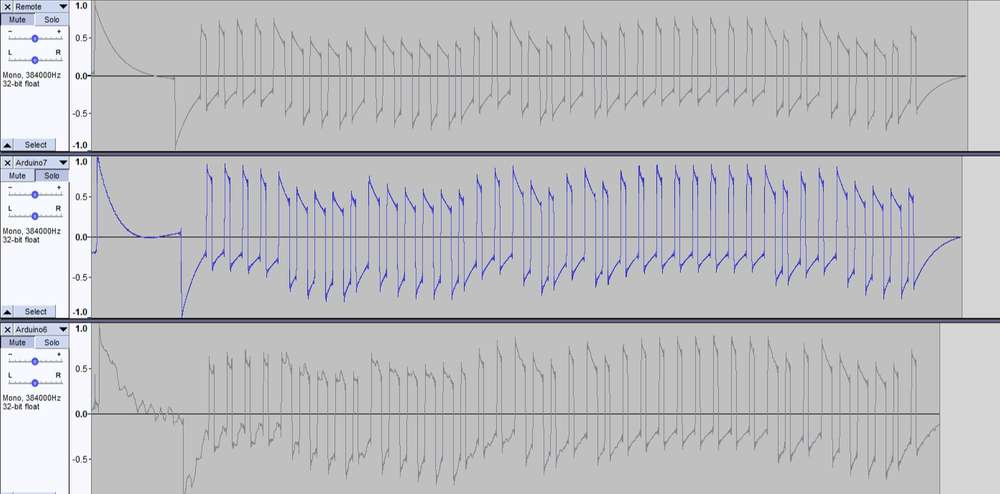
  • @ssuckow what you’ve posted seems to be a good match for the original.
    I’m wondering, based on your other comments, if your blinds need the message repeating several times (with my blinds it’s 4 times) or if the initial message is a sort of ‘stand by to receive a command’ instruction that needs to then be followed by the command message (maybe multiple times?).
    Try quickly stabbing at the remote control button whilst recording in Audacity and look at the bigger picture. This might give you a bigger picture of the complete command set that the remote is sending when a button is pressed.

    Pete.


  • @PeteKnight I'm also trying to control my Gaviota awnings with no success, my remote is not from Gaviota but a white label one (It says it uses rolling codes - it's the MX96 https://cloud.motorline.pt/download/manuais/eletronica/mx95-96-97_pt.pdf). I've tried decoding the codes with a cheap RF receiver hooked up with an ESP32 with espHome. I can get some codes sometimes, if I keep my finger pressed for a long time, but none of them work and they do not seam consistent. Since I do not have a raspberry I cannot run that code from Raspi-Rollo.

    How did you use audacity to decode the codes? Would you mind sharing the codes you got so I can see if they work here? I have 2 awnings, and I can select which one I control on the remote, does that mean that they are using different codes?

    Thanks


  • @mmartins if you re-read what I wrote, you’ll see that the Raspi-Rollo software has an Arduino sketch to identity the codes. I ran this on a NodeMCU, so it should work on an ESP32.
    If you need to use Audacity then the process is well documented in the links earlier in this topic.

    I have three blinds and they all use independent remotes and each blind has its own codes.
    I’m not sure how my codes will help with yours, but here are the codes for one of my blinds:

    Up
    1011101000110000111011101001000100010001

    Stop
    1011101000110000111011101001000101010101

    Down
    1011101000110000111011101001000100110011

    If your blinds do actually use rolling codes the I don’t think you’ll be able to control them the same way that I do.

    Pete.


  • This post is deleted!


  • This post is deleted!


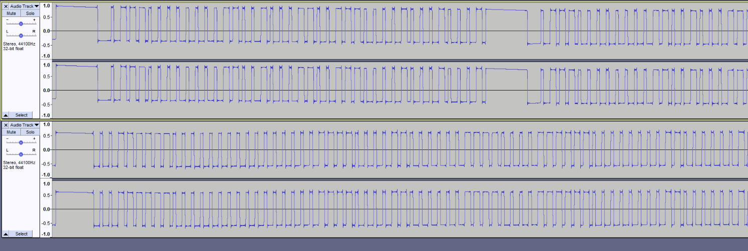
  • @petewill I've managed to get the binary code with Audacity quite easy but got stuck as for each button pressed sends out a combination of codes.

    Just for the open, always the same code in binary, 0111000000001100100011001110000100011110 twice and then 0111000000001100100011001110000100010001 three times.

    //Define Variables
    #define SEND_DATA 3 //Data pin for RF Transmitter
    #define ZERO_HIGH 376 //Delay for the high part of a 0 in microseconds
    #define ZERO_LOW 648 //Delay for the low part of a 0 in microseconds
    #define ONE_HIGH 713 //Delay for the high part of a 1 in microseconds
    #define ONE_LOW 306 //Delay for the low part of a 1 in microseconds
    
    int startUp = 1;
    
    unsigned char standardBits1 = 0b01110000; //sequence with "0b" prefix
    unsigned char standardBits2 = 0b00001100;
    unsigned char standardBits3 = 0b10001100;
    unsigned char standardBits4 = 0b11100001;
    unsigned char standardBits5 = 0b00011110;
    unsigned char standardBits6 = 0b00010001;
    int steps = 1;
    
    //0111000000001100100011001110000100011110  x2
    //0111000000001100100011001110000100010001  x3
    
    void setup() {
       
       Serial.begin(9600);
     
    }
    
    void loop() 
    {
     
      if(startUp == 1)
      {
        
    
      oneBits(standardBits1);
      oneBits(standardBits2);
      oneBits(standardBits3);
      oneBits(standardBits4);
      oneBits(standardBits6);
    
      twoBits(standardBits1);
      twoBits(standardBits2);
      twoBits(standardBits3);
      twoBits(standardBits4);
      twoBits(standardBits5); 
    
      startUp = 1;          //to keep repeating
      delayMicroseconds(5000);
      }
    
    }
    
    void oneBits(unsigned char bits){
        
        unsigned char k;
        int delayTime;
        for(k=0;k<8;k++) {
          int highTime;
          int lowTime;
          delayTime = ((bits>>(7-k)) & 1 ? 1 : 0); 
          
          if (delayTime == 1){
            highTime = ONE_HIGH;
            lowTime = ONE_LOW;
          }
          else {
            highTime = ZERO_HIGH;
            lowTime = ZERO_LOW;
            digitalWrite(SEND_DATA, HIGH);
            delayMicroseconds(highTime);
            digitalWrite(SEND_DATA, LOW);    
            delayMicroseconds(lowTime);
            }
        }
        
    
    }
    void PAUSE()
    {
    delayMicroseconds(1650);
    }
    
    
    void twoBits(unsigned char bits)
    {
    
        unsigned char l;
        int delayTime;
        for(l=0;l<8;l++)
            {
              
           
          int highTime;
          int lowTime;
          delayTime = ((bits>>(7-l)) & 1 ? 1 : 0); 
        
          if (delayTime == 1){
            highTime = ONE_HIGH;
            lowTime = ONE_LOW;
          }
          else {
            highTime = ZERO_HIGH;
            lowTime = ZERO_LOW;
            }      
          
            digitalWrite(SEND_DATA, HIGH);
            delayMicroseconds(highTime);
            digitalWrite(SEND_DATA, LOW);    
            delayMicroseconds(lowTime);
          }
            }   
    

    I'm seeing the 'results' back on Audacity since the code is set on a loop. Not to complicate more I'm just using 2 different codes but they are broadcasted to each other.

    Is there anything I could do to separate them as any delay in between the processes won't work??

    Thanks

    Carl


  • Admin

    @carlscic Sorry, I'm not clear on what you're looking to do. Have you compared the original Audacity recording to the signals you are sending from the Arduino? You should be able to compare them and make the necessary adjustments to the code so the two recordings are identical.


  • @petewill what I'm trying to do is send 5 codes. Right now the 433 transmitter will broadcast the codes together, one after the other without any delay which the receiver won't recognize.

    433audio.PNG

    I already have a written program to control these blinds with a stepper motor to open and close but since they have a built-in motor for shades angle it would be an upgrade!


  • Admin

    @carlscic Sorry for the delay. I didn't get a notification of your reply due to some issues caused by the Google outage. Looks like you're almost there. Try playing around with the delays. You might need to adjust the separatorDelay delay times (or maybe remove that call completely). They it just comes down to iterating though the code to make sure you're getting the correct sequence of highs and lows. Playing back your results and recording them in Audacity is a great way to see your results.


  • @petewill Hey Pete, this is a great project and I'm trying to do something similar but I had Budget Blinds installed in my new home and they seem to be very locked down to protect the dealer/partner channel. Apparently the remotes and automation stuff are made by Somfy and operate on 433.42 MHz.

    I started with the project as you describe in this thread, I've been trying to use the terminal monitor with no real results so my next step is to try using audacity to capture the data. If my equipment operates on 433.42 is this problematic? Is it possible to tune the Arduino receiver or does it operate on a wide enough range to capture that? I just want to create a Vera scene to open and close the blinds at specific times.

    I hope it's OK to revive this older thread.


  • @jluvs2ride Somfy uses a rolling code, so recording the code and playing it afterwards will not work since the code is changing all the time. This may help you:
    https://www.nodo-shop.nl/en/rflink-gateway/193-rflink-43342-gateway-components-somfy-rts.html


  • Hello everyone,

    Firstly, I apologize for reviving such an old thread, but I find myself in a unique situation and was hoping some of you might be able to help.

    I hope everyone's doing well. I have a specific inquiry that I couldn't find a recent solution for. Does anyone here know of a tool to generate "fake" Dooya remote (DC90) RF codes for curtains? I've acquired a few motors without controllers and am trying to integrate them with Home Assistant and Bradlink RF remote. Specifically, I'm searching for a way to generate codes for the Up, Down, Stop, and the "Set" button functions to configure curtain limits.

    Any insights or guidance would be immensely appreciated. Thank you so much in advance!


Log in to reply
 

Suggested Topics

  • 8
  • 44
  • 29
  • 3
  • 2
  • 1

0
Online

11.2k
Users

11.1k
Topics

112.5k
Posts