3D printed housing for an MQTT-GW
-
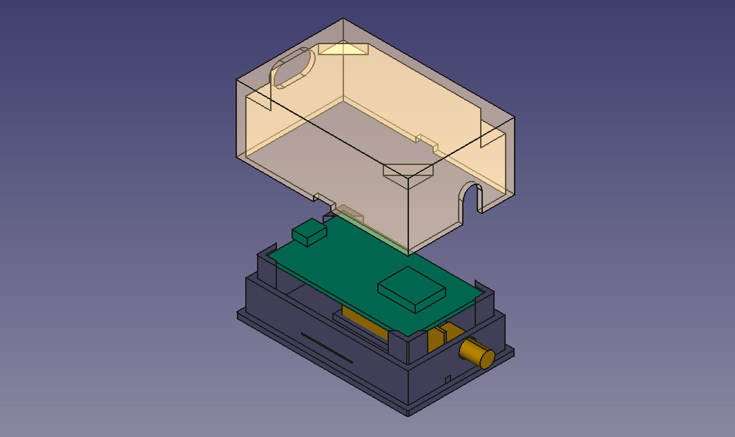
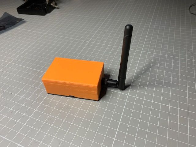
I recently designed a housing for my MQTT-Gateway, based on an ESP8266 module (Node-MCU) and an nRF24L01+PA+LNA. The housing printed great using PLA on my FF Creator Pro. Connections are made using Dupont cables cut in half and soldered directly to the nRF24 where the pins have been removed. I enclose a picture from FreeCad and a link to the stl-files on Github for the base and the cover.


-
Thanks for the contribution.
You could maybe upload it also to www.thingiverse.com, so that more people can find it :-) -
Hi,
If there is interest here is a model that i've made for MQTT-GW targeting the Wemos D1 Mini and RFM69 radios. https://www.thingiverse.com/thing:4657916
It's a pack with two models for table or wall mounting.
BR
//Anders -
Hi,
If there is interest here is a model that i've made for MQTT-GW targeting the Wemos D1 Mini and RFM69 radios. https://www.thingiverse.com/thing:4657916
It's a pack with two models for table or wall mounting.
BR
//Anders@boanjo a very nice design, not only functional, but also pleasing to the eye.
I've seen your same based design for the temperature node on your thingiverse account, I like that.
I think that I can sell this to my wife to put that in the house :-)Where did you buy your pro mini's? How did you get a deep sleep consumption of only 35 µA?
See my adventures : https://forum.mysensors.org/topic/4796/battery-powered-sensors/242 -
@boanjo a very nice design, not only functional, but also pleasing to the eye.
I've seen your same based design for the temperature node on your thingiverse account, I like that.
I think that I can sell this to my wife to put that in the house :-)Where did you buy your pro mini's? How did you get a deep sleep consumption of only 35 µA?
See my adventures : https://forum.mysensors.org/topic/4796/battery-powered-sensors/242@evb Thanks, yes my wife liked it too so all good :-D
Unfortunately Thingiverse looses track on many designs so i only see half of my own designs even if the direct links work, so nice to see that someone found it anyway. The last batch of Minis i use is these ones https://www.ebay.com/itm/323377378845 but it's the same 8MHz 3.3V that i've used for several years. I've probably consumed 40-50 in various projects and i haven't had a single failure. The voltage regulators are crap of course but following the normal mysensor battery powered recommendations you will remove that. https://www.youtube.com/watch?v=91aFByn90RY here is another video where i'm looking more in detail on the DC powered temp sensor that gets a nice ldo low quiescent voltage regulator. Then it's at 120uA but that is the plain MySensors temp sketch with no modifications.
120uA will probably take you quite far if your sensor is not reporting too frequently any if you need to go even lower then you need even better step up or LDO and also patch some MySensor behaviours. I've built sensors before with a sleep current of 4uA following the exellent tips of Nick Gammon http://www.gammon.com.au/forum/?id=11497 but again that was not using MySensors or RFM69 chips but rather plain ook chips like this one (https://github.com/boanjo/rain_sensor). But i try to stay at master MySensor and take a small hit in sleep current as it's good enough in most cases
Cool! I need to read up on that long thread :)!
-
Thanks for the contribution.
You could maybe upload it also to www.thingiverse.com, so that more people can find it :-)
