Starting my PC with a 3.3v arduino pro mini?
-
So I think I understand the main part of your drawing: The optocoupler keeps the Arduino circuit separate from the mainboard circuit to prevent a short. The resistor is for the diode inside the optocoupler.
There are a few things about your drawing that I don't understand:
- Why is there a 5V powerline with a diode?
- What does the MB stand for? Mainboard
- Why are there two connection points from the Mainboard? Is one reset?
I tried my first Fritzing to make sense of this and to show how I would design the connections (doesn't mean it's right).
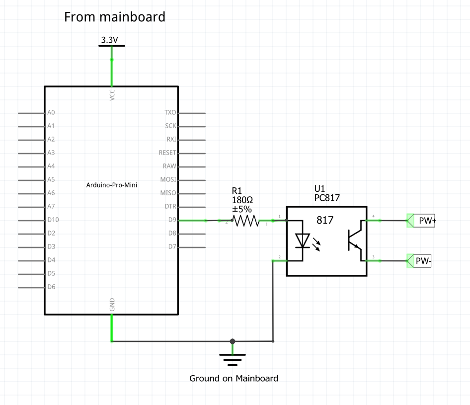
PW+ and PW- are the pins from the schematic in the first post. , 3,3V and GND are available on another set of pins on the mainboard. Would this work?
-
So I think I understand the main part of your drawing: The optocoupler keeps the Arduino circuit separate from the mainboard circuit to prevent a short. The resistor is for the diode inside the optocoupler.
There are a few things about your drawing that I don't understand:
- Why is there a 5V powerline with a diode?
- What does the MB stand for? Mainboard
- Why are there two connection points from the Mainboard? Is one reset?
I tried my first Fritzing to make sense of this and to show how I would design the connections (doesn't mean it's right).
PW+ and PW- are the pins from the schematic in the first post. , 3,3V and GND are available on another set of pins on the mainboard. Would this work?
@kiesel Great work! :)
- 5V connected through diode to protect of polarity revers
- MB = Motherboard, you right
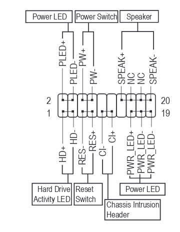
- First need to connect power button from front panel, second to connect to "Power Switch" on motherboard. This allows power on both from power button and Arduino.
You disign is absolutely working!
-
@kiesel Great work! :)
- 5V connected through diode to protect of polarity revers
- MB = Motherboard, you right
- First need to connect power button from front panel, second to connect to "Power Switch" on motherboard. This allows power on both from power button and Arduino.
You disign is absolutely working!
Cool, thank you for your help!
Should I use a diode between 3.3v and GND too? And do I need a resistor in the mainboard-side of the schematic? Some people used them to protect the optocoupler from high current but I guess there isn't a high current when the power button is pressed?
-
Cool, thank you for your help!
Should I use a diode between 3.3v and GND too? And do I need a resistor in the mainboard-side of the schematic? Some people used them to protect the optocoupler from high current but I guess there isn't a high current when the power button is pressed?
-
@kiesel I don't undestand - why you want to use diode between 3.3V and GND?
About resistor on the mainboard side - i don't use it and all works fine :) -
To protect from polarity reversing, like you did in your sketch. Sorry if that's a stupid question!
-
@kiesel See for example this for understand the idea:
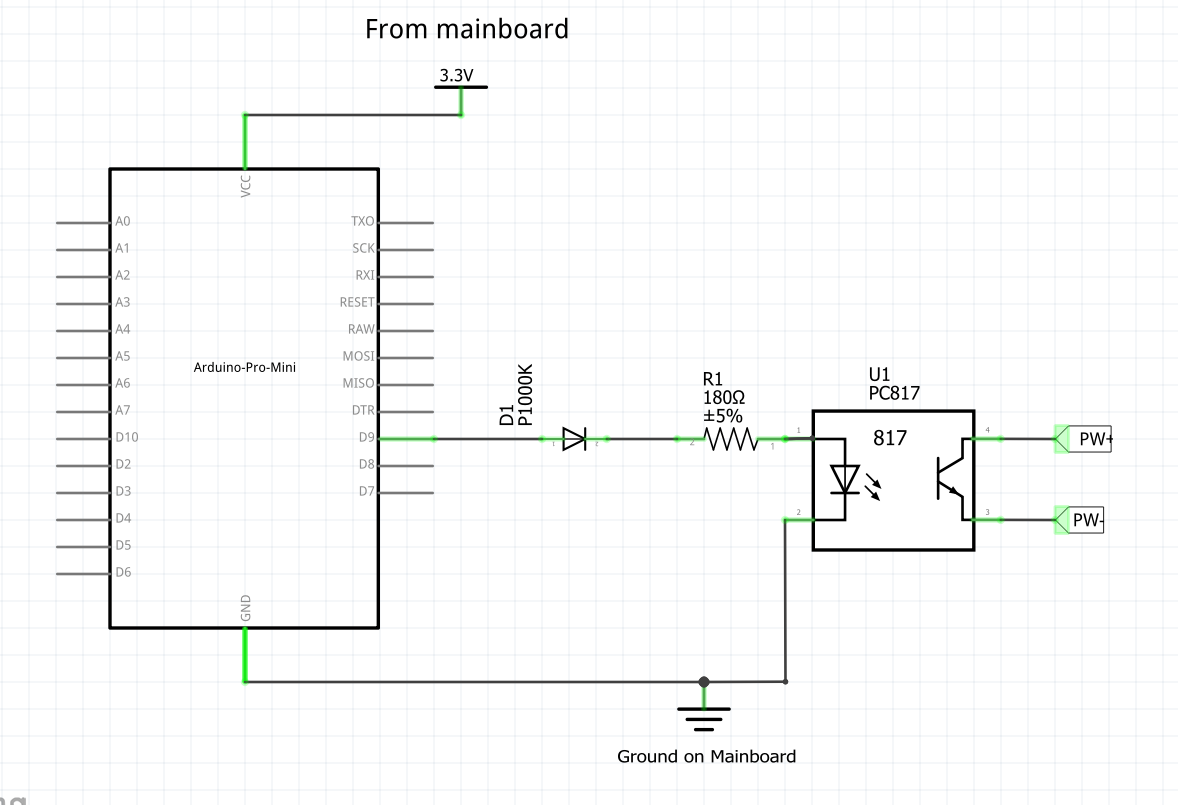
https://www.allaboutcircuits.com/technical-articles/how-to-protect-your-circuits-using-only-a-diode/Ah, ok, I get it now. The diode protects me from wiring this up with POWER and GND switched. So I would use it like this
But I guess I can't because of the voltage drop. I think that's out of specs for the PC817. And anyway there is a very low chance that I will wiring this side of the schematic up wrong.
I guess I was just confused by the lower part of your drawing.
Thank you VERY much for your patience! I'll supply pictures when I have this hooked up in the hopes they will help others.
Have a nice weekend!
-
Ah, ok, I get it now. The diode protects me from wiring this up with POWER and GND switched. So I would use it like this
But I guess I can't because of the voltage drop. I think that's out of specs for the PC817. And anyway there is a very low chance that I will wiring this side of the schematic up wrong.
I guess I was just confused by the lower part of your drawing.
Thank you VERY much for your patience! I'll supply pictures when I have this hooked up in the hopes they will help others.
Have a nice weekend!
-
@kiesel Sorry friend, I guess I confused you a little ..
The diode is needed so that, when powered from the contacts on the motherboard with 5V, it does not damage my arduino, that's all :)
Have a nice weekend to! -
If I wanted this protection where would I put it in my schematic? :)
Between ground an 3.3v?
/edit: no between the arduino and 3.3v from the Mainboard, right?
-
@kiesel said in Starting my PC with a 3.3v arduino pro mini?:
It wouldn't be logic to put it between the opto coupler and the Arduino pin. Because it's purpose is to separate the 2 circuits. Hence protecting both circuits. At least that's how I understand how Opto Couplers work. The opto coupler connects 2 circuits trough light no physical contact. -
So, I finally got this done and it works just like I want it to. I used my initial schematics (plus radio, of course) and this code:
/**
 * The MySensors Arduino library handles the wireless radio link and protocol
 * between your home built sensors/actuators and HA controller of choice.
 * The sensors forms a self healing radio network with optional repeaters. Each
 * repeater and gateway builds a routing tables in EEPROM which keeps track of the
 * network topology allowing messages to be routed to nodes.
 *
 * Created by Henrik Ekblad <henrik.ekblad@mysensors.org>
 * Copyright (C) 2013-2015 Sensnology AB
 * Full contributor list: https://github.com/mysensors/Arduino/graphs/contributors
 *
 * Documentation: http://www.mysensors.org
 * Support Forum: http://forum.mysensors.org
 *
 * This program is free software; you can redistribute it and/or
 * modify it under the terms of the GNU General Public License
 * version 2 as published by the Free Software Foundation.
 *
 *******************************
 *
 * REVISION HISTORY
 * Version 1.0: Yveaux
 *
 * DESCRIPTION
 * This sketch provides an example of how to implement a humidity/temperature
 * sensor using a Si7021 sensor.
 *
 * For more information, please visit:
 * http://www.mysensors.org/build/humiditySi7021
 *
 */

// Enable debug prints
#define MY_DEBUG

#define MY_OWN_DEBUG

#ifndef MY_OWN_DEBUG //disable serial in production compile, potentially saves few uA in sleep mode
     #define MY_DISABLED_SERIAL
#endif


// Enable and select radio type attached
#define MY_RADIO_RFM69
#define MY_IS_RFM69HW
#define MY_RFM69_NEW_DRIVER


#define MY_NODE_ID 5
#define CHILD_ID_TXT 0
#define OUTPIN 8
#include <MySensors.h>


#define SKETCH_NAME "media_pc_switch"
#define SKETCH_MAJOR_VER "1"
#define SKETCH_MINOR_VER "0"

static bool metric = true;

MyMessage msgTxt(CHILD_ID_TXT, V_TEXT);
void presentation()
{
   // Send the sketch version information to the gateway and Controller
  sendSketchInfo(SKETCH_NAME, SKETCH_MAJOR_VER "." SKETCH_MINOR_VER);
  present(CHILD_ID_TXT, S_INFO);
}
void setup()
{
   pinMode(OUTPIN, OUTPUT);    //
   digitalWrite(OUTPIN, LOW);
   #ifdef MY_OWN_DEBUG
      Serial.print("Starting: ");
  #endif
  send(msgTxt.set("Ready"));
}

void receive(const MyMessage &msg)
{
  uint16_t ms;
  Serial.print("Received a message: ");
  Serial.println(msg.getString());
  send(msgTxt.set(msg.getString()));
  ms = msg.getUInt();
  if (ms > 10000 || ms < 1){return;}
  send(msgTxt.set("Received"));
  Serial.println("Pulling pin high");
  digitalWrite(OUTPIN, HIGH);
  Serial.print("Waiting for "); Serial.println(ms);
  delay(ms);
  Serial.println("Switching off");
  digitalWrite(OUTPIN, LOW);
  Serial.println("Delaying a few seconds to ignore message resends.");
  send(msgTxt.set("Sleeping"));
  delay(10000);
  send(msgTxt.set("Ready"));


}
Now I can use this sequence in HA to start my PC even when the power was cut:
wzimmer_ms_start_htpc:
  alias: Use mysensors node 5 to start the mediapc in the living room
  sequence:
    repeat:
      sequence:
        #don't run if htpc already running
          - condition: not
            conditions:
            - condition: state
              entity_id: binary_sensor.htpc
              state: 'on'
        #send start signal to mysensors
          - service: notify.mysensors
            data:
              target: "media_pc_switch 5 0"
              message: 1000
        #wait for timeout seconds whether a message has been received
          - wait_for_trigger:
            - platform: state
              entity_id: sensor.media_pc_switch_5_0
              to: "Received"
            timeout: '00:00:04'
      until:
          # Did it work?
          - condition: state
            entity_id: sensor.media_pc_switch_5_0
            state: Received
Thank you, @cabat for your help and your patience!!! :)
Hello! It looks like you're interested in this conversation, but you don't have an account yet.
Getting fed up of having to scroll through the same posts each visit? When you register for an account, you'll always come back to exactly where you were before, and choose to be notified of new replies (either via email, or push notification). You'll also be able to save bookmarks and upvote posts to show your appreciation to other community members.
With your input, this post could be even better 💗
Register Login