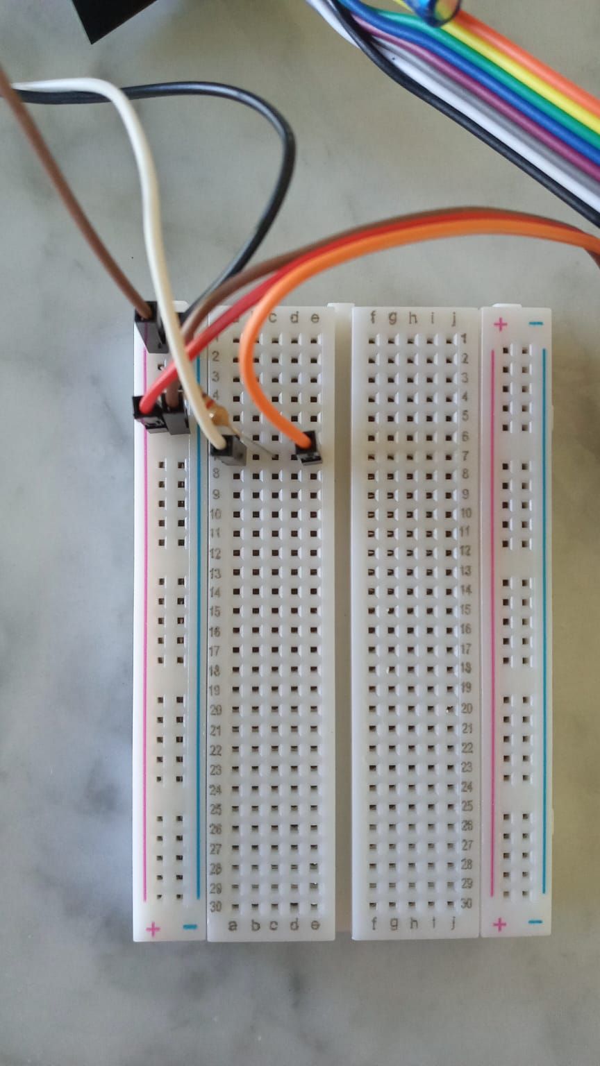
Connecting the Dallas DS18B20 temperature sensor.
-
Hello everyone, I am building a temperature sensor using the Dallas DS18B20 sensor. I have a couple of question about it's connection. I am using a arduino nano and have the NRF24L01+ connected to the 3.3v pin. To connect the sensor, is it ok to plug it into the 5v pin? it says to plug it into the vcc pin but I dont know the ouput voltage of it and the documentation says (3.0-5.5V). In addition, I am using a 4,7kOhm resistor. another question I have is on the connection of the resistor. I dont understand why the documentation says I have to plug it between the vcc and d3, How is that? Isnt a resistor supposed to stand in te middle of a connection?
 This is how I connected it, the resistor makes a bridge from the d3 to the vcc. Is this ok? (The orange cable is coming from the pin 3 and goes to the dq of the sensor, the red cable comes from the 5v and goes to the vcc of the sensor and the black comes form the gnd and goes to the gnd of the sesor).
Hope this is well explained :) . -
Hello everyone, I am building a temperature sensor using the Dallas DS18B20 sensor. I have a couple of question about it's connection. I am using a arduino nano and have the NRF24L01+ connected to the 3.3v pin. To connect the sensor, is it ok to plug it into the 5v pin? it says to plug it into the vcc pin but I dont know the ouput voltage of it and the documentation says (3.0-5.5V). In addition, I am using a 4,7kOhm resistor. another question I have is on the connection of the resistor. I dont understand why the documentation says I have to plug it between the vcc and d3, How is that? Isnt a resistor supposed to stand in te middle of a connection?
 This is how I connected it, the resistor makes a bridge from the d3 to the vcc. Is this ok? (The orange cable is coming from the pin 3 and goes to the dq of the sensor, the red cable comes from the 5v and goes to the vcc of the sensor and the black comes form the gnd and goes to the gnd of the sesor).
Hope this is well explained :) .@Feliw05 the resistor is called a pull-up resistor. See https://en.m.wikipedia.org/wiki/Pull-up_resistor
As you have noted, any voltage between 3.0 and 5.5 for power supply will work so it doesn’t make much difference whether you connect 3.3V or 5.0V.
-
so I am guessing the resistor is placed correcty? Thank you very much for your replay, it has been extremely helpful.
-
@mfalkvidd said in Connecting the Dallas DS18B20 temperature sensor.:
I don't know. Where do the two brown wires go to?
@mfalkvidd the one on the right goes to vcc of the sesnor and the left one goes to the gnd of the arduino nano. The other white and orange cable go to pin 3.
-
@mfalkvidd said in Connecting the Dallas DS18B20 temperature sensor.:
I don't know. Where do the two brown wires go to?
@mfalkvidd the one on the right goes to vcc of the sesnor and the left one goes to the gnd of the arduino nano. The other white and orange cable go to pin 3.
