Skip to content
  • MySensors
  • OpenHardware.io
  • Categories
  • Recent
  • Tags
  • Popular
Skins
  • Light
  • Brite
  • Cerulean
  • Cosmo
  • Flatly
  • Journal
  • Litera
  • Lumen
  • Lux
  • Materia
  • Minty
  • Morph
  • Pulse
  • Sandstone
  • Simplex
  • Sketchy
  • Spacelab
  • United
  • Yeti
  • Zephyr
  • Dark
  • Cyborg
  • Darkly
  • Quartz
  • Slate
  • Solar
  • Superhero
  • Vapor

  • Default (No Skin)
  • No Skin
Collapse
Brand Logo
  1. Home
  2. Troubleshooting
  3. Gateway doesn't receive any message from node

Gateway doesn't receive any message from node

Scheduled Pinned Locked Moved Troubleshooting
25 Posts 3 Posters 157 Views 3 Watching
  • Oldest to Newest
  • Newest to Oldest
  • Most Votes
Reply
  • Reply as topic
Log in to reply
This topic has been deleted. Only users with topic management privileges can see it.
  • Y Offline
    Y Offline
    yury
    wrote on last edited by
    #15

    @ctodor said in Gateway doesn't receive any message from node:

    GW ia not totally mute

    Better to have 3-rd device to play with. Preferably 3.3 V one. RFM is 3.3 volts radio. not sure if you used logic level shifters for Nano digital pins connected to radio. Also, SDR radio is handy to detect any radio emission.

    C 1 Reply Last reply
    0
    • Y yury

      @ctodor said in Gateway doesn't receive any message from node:

      GW ia not totally mute

      Better to have 3-rd device to play with. Preferably 3.3 V one. RFM is 3.3 volts radio. not sure if you used logic level shifters for Nano digital pins connected to radio. Also, SDR radio is handy to detect any radio emission.

      C Offline
      C Offline
      ctodor
      wrote on last edited by
      #16

      @yury
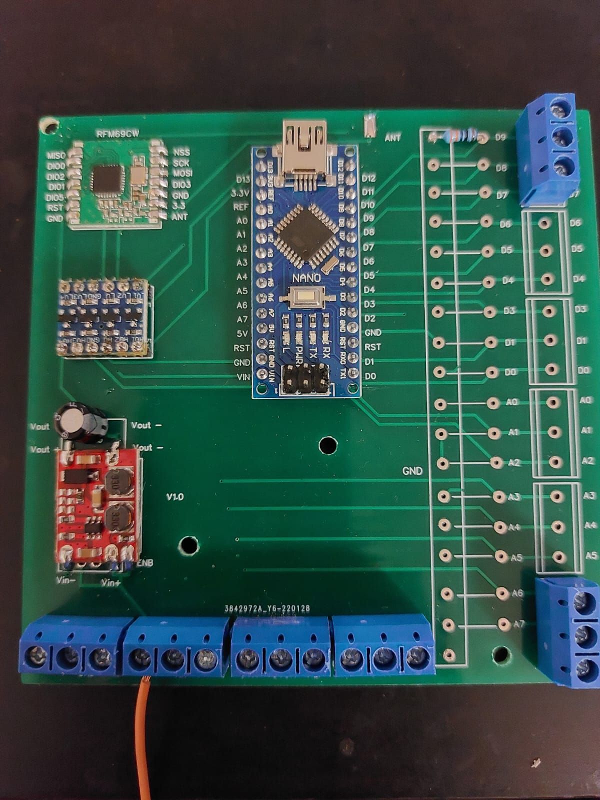
      On the sende side (GW) I'm using Arduino Nano 5v and a logic shifter indeed.
      On the receiver side (Node) I'm using a "prebuild board" purchased from tindie.
      Btw, I think I bought from you, "easySensor" :grin: . Your devices works fine.

      The problem is on the "sender" side, built by me. I've already built two "boards" and both have the same problem. Sending doesn't work.

      1 Reply Last reply
      0
      • Y Offline
        Y Offline
        yury
        wrote on last edited by
        #17

        @ctodor said in Gateway doesn't receive any message from node:

        I bought from you, "easySensor"

        Yes. :+1:

        may be detailed photo of the device can help...

        1 Reply Last reply
        0
        • C Offline
          C Offline
          ctodor
          wrote on last edited by
          #18

          Here are the pictures:
          pcb2.jpeg pcb1.jpeg

          But my question (maybe stupid question) is: It is possible the the radio module to be broken only on the "send side"?

          Thank you.

          1 Reply Last reply
          1
          • Y Offline
            Y Offline
            yury
            wrote on last edited by
            #19

            @ctodor said in Gateway doesn't receive any message from node:

            broken only on the "send side"

            As @mfalkvidd said, it is possible to burn with no antenna attached but I never actually did that. RFM is quite reliable. Is Schematics available? I see you have reset pad soldered. reset should be disconnected after reset is completed.

            1 Reply Last reply
            0
            • C Offline
              C Offline
              ctodor
              wrote on last edited by ctodor
              #20

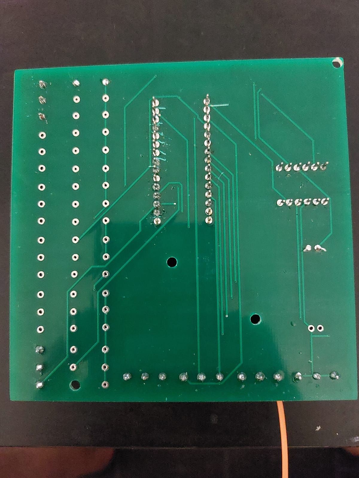
              Unfortunately no schecma available. I've create the pcb on some website (don't know if is ok to say the site name here)
              The reset pad is indeed soldered, but the pad is not connected to anything.
              NSS->LV1->HV1->D10
              SCK->LV2->HV2->D13
              MOSI->LV3->HV3->D11
              MISO->LV4->HV4->D12
              DIO0->D2

              Btw. I've never reset the radio module

              1 Reply Last reply
              0
              • Y Offline
                Y Offline
                yury
                wrote on last edited by
                #21

                pinout looks ok.

                btw This line from the Node log

                1269 !TSF:MSG:SEND,100-100-0-0,s=255,c=3,t=24,pt=1,l=1,sg=0,ft=0,st=NACK:1

                Means node cannot send OR gateway cannot receive. may be node radio is HCW somehow?
                mysensors lib not broken\timeouts not tweaked?

                C 1 Reply Last reply
                0
                • Y yury

                  pinout looks ok.

                  btw This line from the Node log

                  1269 !TSF:MSG:SEND,100-100-0-0,s=255,c=3,t=24,pt=1,l=1,sg=0,ft=0,st=NACK:1

                  Means node cannot send OR gateway cannot receive. may be node radio is HCW somehow?
                  mysensors lib not broken\timeouts not tweaked?

                  C Offline
                  C Offline
                  ctodor
                  wrote on last edited by
                  #22

                  @yury may be node radio is HCW somehow? no, it is not.

                  I'll try to create a new board and give feedback.

                  1 Reply Last reply
                  0
                  • C Offline
                    C Offline
                    ctodor
                    wrote on last edited by
                    #23

                    Update: it seems the problem was the DC-DC convertor. I have replace it with an extwrnal power source and now it works.
                    I still don't understand what was wrong there because the voltage on the radio module was correct:3.3V

                    mfalkviddM 1 Reply Last reply
                    1
                    • C ctodor

                      Update: it seems the problem was the DC-DC convertor. I have replace it with an extwrnal power source and now it works.
                      I still don't understand what was wrong there because the voltage on the radio module was correct:3.3V

                      mfalkviddM Online
                      mfalkviddM Online
                      mfalkvidd
                      Mod
                      wrote on last edited by
                      #24

                      @ctodor nice work!

                      When you checked the voltage, did you use a multimeter or an oscilloscope? If you used a multimeter, maybe there was a ripple or something that wasn’t visible.

                      C 1 Reply Last reply
                      0
                      • mfalkviddM mfalkvidd

                        @ctodor nice work!

                        When you checked the voltage, did you use a multimeter or an oscilloscope? If you used a multimeter, maybe there was a ripple or something that wasn’t visible.

                        C Offline
                        C Offline
                        ctodor
                        wrote on last edited by
                        #25

                        @mfalkvidd multimeter

                        1 Reply Last reply
                        1
                        Reply
                        • Reply as topic
                        Log in to reply
                        • Oldest to Newest
                        • Newest to Oldest
                        • Most Votes


                        17

                        Online

                        11.7k

                        Users

                        11.2k

                        Topics

                        113.1k

                        Posts


                        Copyright 2025 TBD   |   Forum Guidelines   |   Privacy Policy   |   Terms of Service
                        • Login

                        • Don't have an account? Register

                        • Login or register to search.
                        • First post
                          Last post
                        0
                        • MySensors
                        • OpenHardware.io
                        • Categories
                        • Recent
                        • Tags
                        • Popular