Skip to content
  • OpenHardware.io
  • Categories
  • Recent
  • Tags
  • Popular
Skins
  • Light
  • Brite
  • Cerulean
  • Cosmo
  • Flatly
  • Journal
  • Litera
  • Lumen
  • Lux
  • Materia
  • Minty
  • Morph
  • Pulse
  • Sandstone
  • Simplex
  • Sketchy
  • Spacelab
  • United
  • Yeti
  • Zephyr
  • Dark
  • Cyborg
  • Darkly
  • Quartz
  • Slate
  • Solar
  • Superhero
  • Vapor

  • Default (No Skin)
  • No Skin
Collapse
Brand Logo
  1. Home
  2. Hardware
  3. Roller Shutter
  • Getting Started
  • Controller
  • Build
  • Hardware
  • Download/API
  • Forum
  • Store

Roller Shutter

Scheduled Pinned Locked Moved Hardware
87 Posts 23 Posters 57.5k Views 32 Watching
  • Oldest to Newest
  • Newest to Oldest
  • Most Votes
Reply
  • Reply as topic
Log in to reply
This topic has been deleted. Only users with topic management privileges can see it.
  • F Offline
    F Offline
    Fabien
    wrote on last edited by
    #15

    Take car about antenna position (no metal just under the antenna). I experience some issues with sensebender micro and FTDI connector just under the antenna. And perhaps you can use small SSR relay.

    1 Reply Last reply
    0
    • tbowmoT Offline
      tbowmoT Offline
      tbowmo
      Admin
      wrote on last edited by
      #16

      @scalz

      As @Fabien just mentioned, you should keep the area under, and around, the antenna of the NRF clear of any tracks, and components.. Otherwise you are asking for trouble..

      1 Reply Last reply
      0
      • scalzS Offline
        scalzS Offline
        scalz
        Hardware Contributor
        wrote on last edited by scalz
        #17

        @Fabien @tbowmo: thank you very much for your feedback.
        So no tracks under the chip, or on the other plane? Arrgh, I will try. Is it related to nrf because on moteino designs it seems rfm don't care about it? Anyway I don't want to have problems. I don't know how I will do that but I will see this evening.Last night, I added spi for programmer so it's cool. I found capa for snubber but 2220 size...

        And for small SSR, I thought about it but the board must handle 12/24v motors too so current won't be the same and small SSR won't like that. That is why I choosed these relays. I want to be able to handle 12/24 and 220v so the board would be useful for lots of application.
        I was lazy to move to kicad but I will move for sure :flushed:

        1 Reply Last reply
        0
        • F Offline
          F Offline
          Fabien
          wrote on last edited by
          #18

          No track under the chip. I use kicad for few years now and it's ok !

          1 Reply Last reply
          0
          • scalzS Offline
            scalzS Offline
            scalz
            Hardware Contributor
            wrote on last edited by
            #19

            @fabien: so not under chip, but other side of board is ok i think? Anyway, I think I will have to do some reroute. Not easy. I am not electronician. I'm database soft archi. So I have not done lots of pcb yet. I am learning.. but at my job I played a lot with mikroelectronika even if I am not in charge to design pcb.
            And I think I made a wrong choice with eagle (I saw lots of libs so I thought it would be easier. But I have to make lots of parts myself so...).
            Here what I did last night : moved ant smd for rfm, spi connector, and 3d model for stepdown. Not a lot of things. And, tried to place snubber, but not good, clearance drc errors..I am thinking to add snubber externally.
            Untitled.jpg Untitled2.jpg Next screenshot I hope all will be ok :smiley:

            @tbowmo: which tools do you use to create 3d models for Kicad? I tried Sketchup yesterday but don't like interface as I usually use Solidworks at job when needed. Would be great if I could export Solidworks to kicad, I will see if it's possible..

            1 Reply Last reply
            0
            • tbowmoT Offline
              tbowmoT Offline
              tbowmo
              Admin
              wrote on last edited by
              #20

              @scalz

              rfm modules have an external antenna, that is why they can be mounted like they do on moteino boards.

              NRF modules incorporates an anteanna, and you need to keep the anteanna area (+ some space around it) clear of components and tracks. on both sides of the PCB. Otherwise they will interfere with the antenna radiation.

              I use the build in 3D viewer in kicad. (Using almost bleeding edge of kicad on linux, with additions from CERN)

              1 Reply Last reply
              0
              • scalzS Offline
                scalzS Offline
                scalz
                Hardware Contributor
                wrote on last edited by
                #21

                @tbowmo: thank you for your explanation. So I think it is not a good news for me (nrf24) aaaaaaa I will loose my hairs on this:sweat_smile: even if I plan to use rfm, my brother have a lots of nrf24. I think he will need move to rfm. But I will try, big challenge for me.
                For kicad, interesting info, thanks.

                1 Reply Last reply
                0
                • scalzS Offline
                  scalzS Offline
                  scalz
                  Hardware Contributor
                  wrote on last edited by
                  #22

                  @Fabien: I have an idea for nrf24 problem, maybe dumb I don't know.

                  • on bottom of nrf, paste piece of paper
                  • then add a piece aluminium sheet or anything else with a wire to connect it to gnd
                  • then paste another piece of paper
                    Do you think it could work? Or maybe antenna will not like the ground plane...
                    just ideas, in case.
                  1 Reply Last reply
                  0
                  • tbowmoT Offline
                    tbowmoT Offline
                    tbowmo
                    Admin
                    wrote on last edited by
                    #23

                    @scalz

                    A gnd plane under the antenna are sure to make troubles, as you effectively short circuit the antenna.

                    1 Reply Last reply
                    0
                    • DwaltD Offline
                      DwaltD Offline
                      Dwalt
                      wrote on last edited by Dwalt
                      #24

                      I have the ftdi header on the sensebender board mounted on the atmel chip side (opposite the radio) and have not had any problems with radio range or packet loss. My deployed sensebenders are all between 3 and 7 meters from gateway or repeater.

                      Veralite UI5 :: IBoard Ethernet GW :: MyS 1.5

                      1 Reply Last reply
                      0
                      • F Offline
                        F Offline
                        Fabien
                        wrote on last edited by
                        #25

                        You can have no problem but sure metallic part modify the diagram antenna. Perhaps with real Nordic there's less problem but for new design it is better to avoid ground plane or tracks on all layers under the antenna.

                        1 Reply Last reply
                        0
                        • scalzS Offline
                          scalzS Offline
                          scalz
                          Hardware Contributor
                          wrote on last edited by
                          #26

                          @tbowmo: ok. so in my case it is not a good idea to put 2 radio footprints as it will increase size. As I have already done the job, I will make 2 versions. easier.
                          In the other hand, the mini pro version (a little bigger) I have already traced could handle both radio with some minor change.

                          So, I have now all recommandation I need. So I am able to finish it and send to fabhouse for test. I will inform you when board and sketch all done.
                          Thanks again to all.

                          1 Reply Last reply
                          0
                          • Daniel OliveiraD Offline
                            Daniel OliveiraD Offline
                            Daniel Oliveira
                            wrote on last edited by
                            #27

                            Hi @scalz

                            A question, there is a reason to do not use an encoder instead of the acs712 and the stop buttons to know the position of the shutter?

                            Cheers

                            MySensors rules my home :)

                            1 Reply Last reply
                            0
                            • scalzS Offline
                              scalzS Offline
                              scalz
                              Hardware Contributor
                              wrote on last edited by
                              #28

                              Hi.
                              I am not sure what do you mean with "stop button" (end stops?) and encoder. I have made this board for multi purpose, not rollershutter only. And in dualrelay, I can know power consumption too.
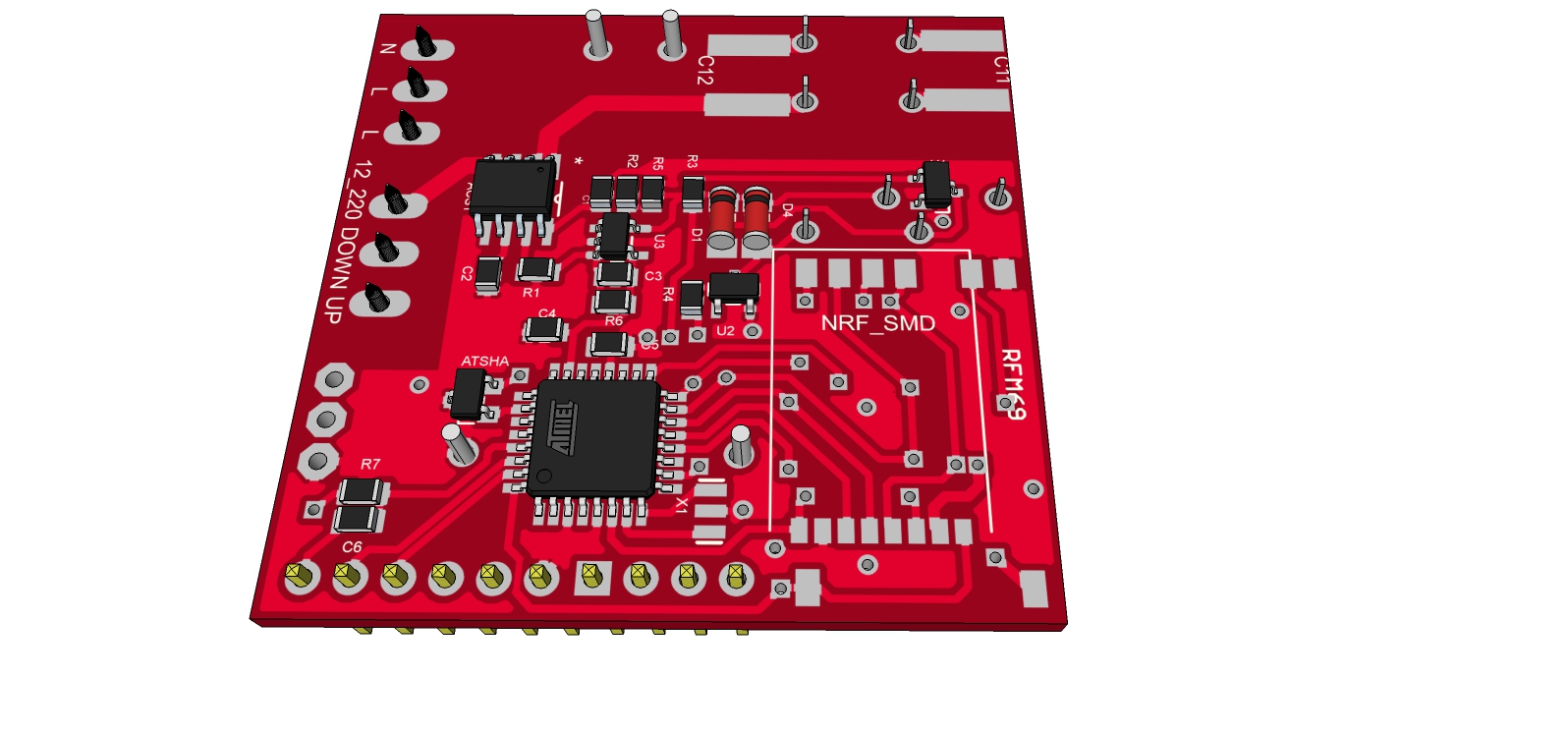
                              I need to update 3d view. But my schematics and pcb are my latest rev. I am waiting for my pcb (end of the month).
                              Maybe there are other good ideas as I am not electronician. But I have learnt a lot at my job and thx to internet:smile:

                              1 Reply Last reply
                              0
                              • scalzS Offline
                                scalzS Offline
                                scalz
                                Hardware Contributor
                                wrote on last edited by
                                #29

                                Hi.

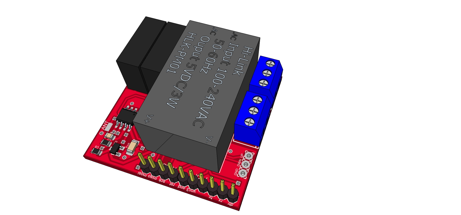
                                just to share :smile: as I have received some boards today. so here a screenshot for rollershutternode.
                                Sans-titre-1.jpg
                                It is not soldered yet, I just wanted to see if my hilink, relays and nrf footprints was ok. it's ok! but too bad I forgot to order varistor and fuses (fuse will be between the screw terminals, and varistor on right bottom corner...
                                these boards was ordered at Seeed.

                                1 Reply Last reply
                                2
                                • J Offline
                                  J Offline
                                  jemish
                                  wrote on last edited by
                                  #30

                                  can you please tell me that what type of roller shutter are use....
                                  where I can buy this roller shutter.

                                  1 Reply Last reply
                                  0
                                  • scalzS Offline
                                    scalzS Offline
                                    scalz
                                    Hardware Contributor
                                    wrote on last edited by
                                    #31

                                    @jemish: I will test it on somfy rollershutter (220v motor). but the board can be used with 12-24-110v motors/load. and I need to finish the rollershutter sketch too and check everything.All will be ok in maybe... two weeks I hope.

                                    1 Reply Last reply
                                    0
                                    • F Offline
                                      F Offline
                                      Fabien
                                      wrote on last edited by
                                      #32

                                      It's exactly what I want. Dimension are fine (fit in wall european round european box). I can't wait 2 weeks :joy:

                                      1 Reply Last reply
                                      0
                                      • F Offline
                                        F Offline
                                        Fabien
                                        wrote on last edited by
                                        #33

                                        @scalz : what the news ? Did you test your board ? I will start a design without Hi-link (LNK306 Or SR086 instead) and triac and I would like to know if you can use current information from hal-effect sensor.

                                        1 Reply Last reply
                                        0
                                        • scalzS Offline
                                          scalzS Offline
                                          scalz
                                          Hardware Contributor
                                          wrote on last edited by
                                          #34

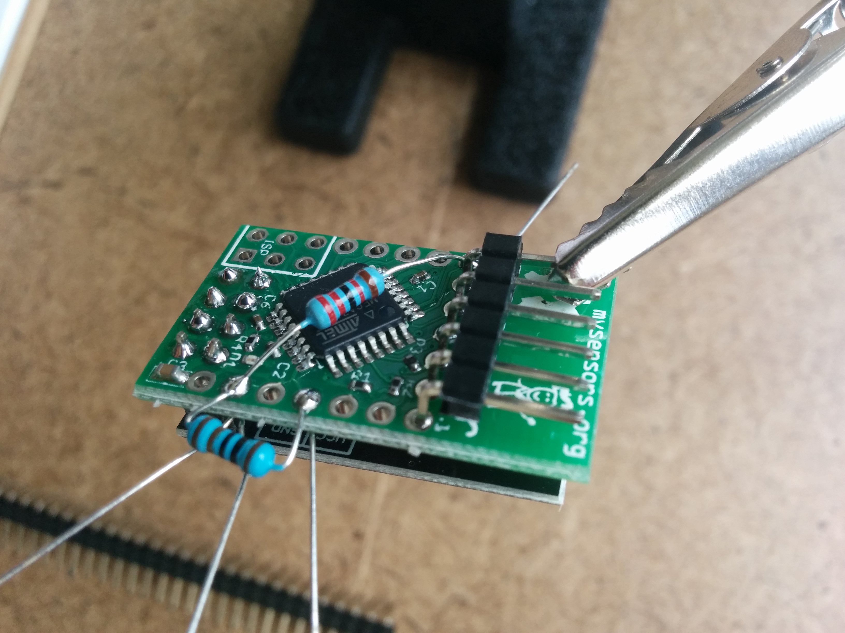
                                          @Fabien: yes I have done some tests and worked on the sketch too.
                                          So for rev 1.0, I have made a mistake on opamp of acs712. not big but a little embarrassing to fix onboard.
                                          Good news is I have no stability problem (regarding relays, button interrupt, or smd nrf near buttons pinheader). I was afraid about that. so it's cool.

                                          Rev 1.1 is finished (but not ordered) and I am working on documentation before release. it won't take long time I hope :wink:
                                          In rev 1.1 :

                                          • opamp for acs712 updated
                                          • 0805 onboard led added (was missing but it can be useful!)
                                          • 0805 CTN for temperature of the board (under hilink)
                                          • better silkscreen

                                          for your question about triac and acs712, I can't tell you. I am not sure, but don't see why it could not work. but if it is for rollershutter node control, I am not sure if triac is best option..

                                          1 Reply Last reply
                                          0
                                          Reply
                                          • Reply as topic
                                          Log in to reply
                                          • Oldest to Newest
                                          • Newest to Oldest
                                          • Most Votes


                                          16

                                          Online

                                          11.7k

                                          Users

                                          11.2k

                                          Topics

                                          113.0k

                                          Posts


                                          Copyright 2019 TBD   |   Forum Guidelines   |   Privacy Policy   |   Terms of Service
                                          • Login

                                          • Don't have an account? Register

                                          • Login or register to search.
                                          • First post
                                            Last post
                                          0
                                          • OpenHardware.io
                                          • Categories
                                          • Recent
                                          • Tags
                                          • Popular