Solar Pannel and LiOn or Lipo
-
thanks, BTW i have 5V arduini too ;-)
-
Here, this is how you connect things:
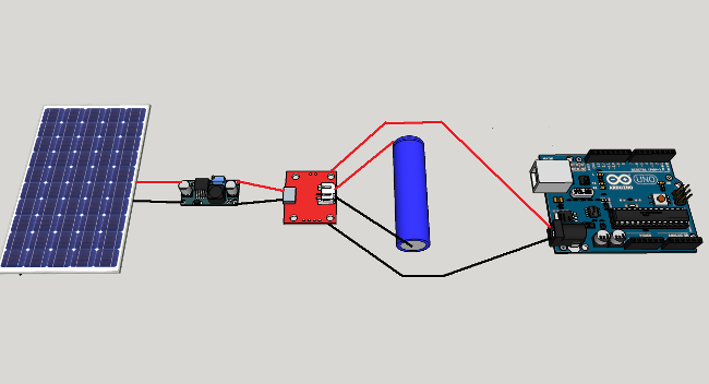
The second item from the left is a DC-DC converter. It is used when the solar panel voltage exceeds 5V. Otherwise it is not needed.
The red board is battery charger. Note that the battery is connected to Batt connections and the Arduino is connected to Out connections, so that the battery protection circuit can do its job.
Arduino is there as an example, I do not think that UNO will even work with such low voltage. -
@ceech thanks a lot for this clear view on how to do it ! So bad there is not one module to make it all.
For the solar panel, I guess it is a security to use the DC-C converter.
For the battery charger, the voltage protection on it is not used in this configuration, right ?What arduino would work here, some 3V3 @ 8Mhz ?
-
@ceech thanks a lot for this clear view on how to do it ! So bad there is not one module to make it all.
For the solar panel, I guess it is a security to use the DC-C converter.
For the battery charger, the voltage protection on it is not used in this configuration, right ?What arduino would work here, some 3V3 @ 8Mhz ?
@epierre
But there is a module that can do all that. This is it:
http://www.ebay.com/itm/331601644681?ssPageName=STRK:MESOX:IT&_trksid=p3984.m1587.l2649The voltage protection IS used in the above configuration and a 3V3 Arduino would work.
-
@ceech yes I saw this one, but I have some hardware to use yet ;-)
do you have an idea of the power of the pannel and the load duration for a CR123 or 18650 that we could consider on making a project ? that would be a good knowledge base for all !
I am also searching for a casing that would be related to the panel size !
-
In fact I've found my answer
"Facts on Battery Charging :
The thumb rule for charging Ni Mh batteries is 1/10th (commonly known as C/10). To charge the battery pack at 1/10th its rated current requires 16 hours of charge time( You can see the picture).The solar panel receives optimal sunlight for only four hours per day, from 10 a.m. to 2 p.m. Thus, a totally ideal system would require four days to fully charge the battery pack.
What is C/10 ?
For example we have a 2xAA–sized 1300mAh battery pack that is rated at 1.2 volts per cell. With cells in series, our pack outputs 2.4 volts and 1300mAh.
Here capacity C =1300mAh
C/10 means 1300/10 =130mAh
So to charge the above battery pack we need a higher voltage ( 2.4 to 3 V) with a maximum current of 130mAh.As per C/10 rule it requires 16 hours to fully charge the battery pack.
You must be ask,what will happen if we increase the current (>130mAh) ?No doubt your battery will charge faster.But the life of the battery will be reduce.So my advice is to keep the current bellow the C/10 value."
Choosing a panel:
"The main source for powering the sensor module is solar panel.So it must be able to provide current for powering the arduino as well as current to charge the battery pack during the day.As per my experience it is the most challenging part for a novice user.
Don't worry these are the following tricks which can help you to buy a right solar panel.
- Voltage : Choose 1.5 times the battery pack voltage
2.Current : Current taken by the Arduino + current for charging (should be
Example :
A battery pack is made of 2 AA Ni Mh battery.
Battery voltage = 1.2 x 2= 2.4V
So required voltage for solar panel =2.4 x 1.5 = 3.6V
By taking some margin we can choose a 4V solar panel for it.
The sensor module along with arduino taking 100mAh current.Battery capacity is 1300mAh
C/10 = 130mAhSolar panel have to provide current 100mAh for arduino along with a current not more than 130mAh.
Lets take 100 mAh for charging the battery
Total current required = 100+100=200mAhFrom the above calculation it is clear that we need a solar panel of 4V and 200mAh.
The following table shows the solar system configuration relationship between storage batteries and mini solar panels.
Battery ----> Solar Panel
1.2V ------> 2V ~ 2.5V
2.4V ------> 3.5V ~ 4V
3.6V ------> 5V ~ 6V
6V ------> 7.5V ~ 9V
12V ------>15V ~ 18VNote : It is not the strict rule for choosing the exact rating solar panel, rather it is approximate rating .I write as per my experience"
- Voltage : Choose 1.5 times the battery pack voltage
-
Here, this is how you connect things:
The second item from the left is a DC-DC converter. It is used when the solar panel voltage exceeds 5V. Otherwise it is not needed.
The red board is battery charger. Note that the battery is connected to Batt connections and the Arduino is connected to Out connections, so that the battery protection circuit can do its job.
Arduino is there as an example, I do not think that UNO will even work with such low voltage.@ceech said:
The second item from the left is a DC-DC converter. It is used when the solar panel voltage exceeds 5V. Otherwise it is not needed.
The red board is battery charger. Note that the battery is connected to Batt connections and the Arduino is connected to Out connections, so that the battery protection circuit can do its job.Hello,
Now I have the item, so:
- B+/B- connected to the voltage regulator of the pannel.- usb port connected to the 18650 / CR123
- +/- near the usb port to the input voltage of the arduino ? or is that out+/out- ?
subsidiary question: what would be the device to use to load a LiFePO4 ?
-
@ceech said:
The second item from the left is a DC-DC converter. It is used when the solar panel voltage exceeds 5V. Otherwise it is not needed.
The red board is battery charger. Note that the battery is connected to Batt connections and the Arduino is connected to Out connections, so that the battery protection circuit can do its job.Hello,
Now I have the item, so:
- B+/B- connected to the voltage regulator of the pannel.- usb port connected to the 18650 / CR123
- +/- near the usb port to the input voltage of the arduino ? or is that out+/out- ?
subsidiary question: what would be the device to use to load a LiFePO4 ?
-
so bad, none worked for a long even with a 6800mAh... it was arduino mini pro ith a 1 W solar panel...
I've moed to your boards to see if I can do better...
-
@epierre
Does the basic functionality work? Do you receive any data from LTC4067?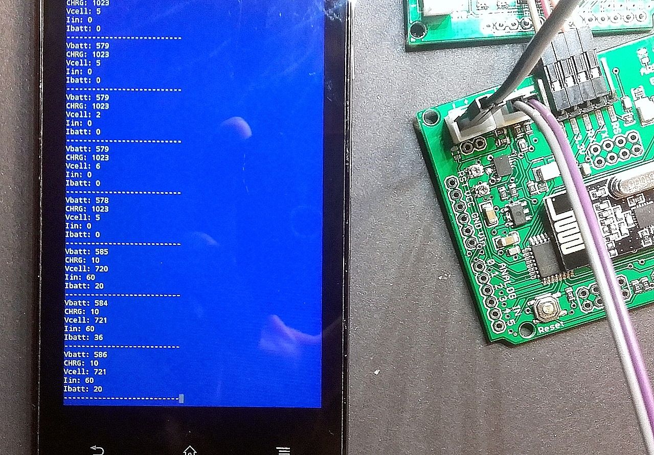
Here is an example of RAW analogRead data from LTC4067.
Notice the /CHRG change from High to Low. That indicates charging.analog input A1 on ATmega 328 is /CHRG signal from LTC4067
analog input A0 on ATmega328 is battery voltage
analog input A2 is solar cell voltage
analog input A6 is input current ( I=V/R x 1000 )
analog input A7 is battery charge current ( I=V/Rprog x 1000 ) -
Here is the code based on the other around:
/* Vera Arduino BH1750FVI Light sensor communicate using I2C Protocol this library enable 2 slave device addresses Main address 0x23 secondary address 0x5C connect the sensor as follows : VCC >>> 5V Gnd >>> Gnd ADDR >>> NC or GND SCL >>> A5 SDA >>> A4 Contribution: idefix/epierre for ceech */ #include <SPI.h> #include <MySensor.h> #include <Wire.h> // I2C #include <BH1750.h> #define LTC4067_CHRG_PIN A1 //analog input A1 on ATmega 328 is /CHRG signal from LTC4067 #define batteryVoltage_PIN A0 //analog input A0 on ATmega328 is battery voltage ( /2) #define solarVoltage_PIN A2 //analog input A2 is solar cell voltage (/ 2) #define solarCurrent_PIN A6 //analog input A6 is input current ( I=V/Rclprog x 1000 ) #define batteryChargeCurrent_PIN A7 //analog input A7 is battery charge current ( I=V/Rprog x 1000 ) #define LTC4067_SUSPEND_PIN 9 //digital output D9 - drive it high to put LTC4067 in SUSPEND mode const float VccMin = 1.0*3.5; // Minimum expected Vcc level, in Volts. Example for 1 rechargeable lithium-ion. const float VccMax = 1.0*4.2; // Maximum expected Vcc level, in Volts. #define LIGHT_SENSOR_ANALOG_PIN 3 // Digital input did you attach your soil sensor. #define CHILD_ID_LIGHT 0 // Id of the sensor child #define BATT_CHILD_ID 10 #define SOLAR_CHILD_ID 11 // PIN Radio #define RADIO_CE_PIN 7 // radio chip enable #define RADIO_SS_PIN 8 // CS SS serial select float lastBattVoltage; float lastBattCurrent; float lastSolarVoltage; float lastSolarCurrent; int lastBattPct = 0; uint16_t lastlux; float VccReference = 3.3 ; // voltage reference for measurement, definitive init in setup BH1750 lightSensor; MySensor gw(RADIO_CE_PIN, RADIO_SS_PIN);; unsigned long SLEEP_TIME = 300*1000; // sleep time between reads (seconds * 1000 milliseconds) MyMessage msg(CHILD_ID_LIGHT, V_LIGHT_LEVEL); MyMessage batteryVoltageMsg(BATT_CHILD_ID, V_VOLTAGE); // Battery voltage (V) MyMessage batteryCurrentMsg(BATT_CHILD_ID, V_CURRENT); // Battery current (A) MyMessage solarVoltageMsg(SOLAR_CHILD_ID, V_VOLTAGE); // Solar voltage (V) MyMessage solarCurrentMsg(SOLAR_CHILD_ID, V_CURRENT); // Solar current (A) int lastSoilValue = -1; void setup() { gw.begin(); // Send the sketch version information to the gateway and Controller gw.sendSketchInfo("Light Lux Sensor", "1.0"); // Register all sensors to gw (they will be created as child devices) gw.present(CHILD_ID_LIGHT, S_LIGHT_LEVEL); gw.present(BATT_CHILD_ID, S_POWER); // Battery parameters gw.present(SOLAR_CHILD_ID, S_POWER); // Solar parameters // use VCC (3.3V) reference analogReference(DEFAULT); // default external reference = 3.3v for Ceech board VccReference = 3.323 ; // measured Vcc input (on board LDO) pinMode(LTC4067_SUSPEND_PIN, OUTPUT); // suspend of Lion charger set digitalWrite(LTC4067_SUSPEND_PIN,LOW); // active (non suspend) at start lightSensor.begin(); } void loop() { sendVoltage(); uint16_t lux = lightSensor.readLightLevel();// Get Lux value Serial.println(lux); if (lux != lastlux) { gw.send(msg.set(lux)); lastlux = lux; } // Power down the radio gw.sleep(SLEEP_TIME); } void sendVoltage(void) // battery and charging values { // get Battery Voltage & charge current float batteryVoltage = ((float)analogRead(batteryVoltage_PIN)* VccReference/1024) * 2; // actual voltage is double Serial.print("Batt: "); Serial.print(batteryVoltage); Serial.print("V ; "); float batteryChargeCurrent = ((float)analogRead(batteryChargeCurrent_PIN) * VccReference/1024)/ 2.5 ; // current(A) = V/Rprog(kohm) Serial.print(batteryChargeCurrent); Serial.println("A "); // get Solar Voltage & charge current float solarVoltage = ((float)analogRead(solarVoltage_PIN)/1024 * VccReference) * 2 ; // actual voltage is double Serial.print("Solar: "); Serial.print(solarVoltage); Serial.print("V ; "); // get Solar Current float solarCurrent = ((float)analogRead(solarCurrent_PIN)/1024 * VccReference)/ 2.5; // current(A) = V/Rclprog(kohm) Serial.print(solarCurrent); Serial.print(" A; charge: "); Serial.println(digitalRead(LTC4067_CHRG_PIN)?"No":"Yes"); // send battery percentage for node int battPct = 1 ; if (batteryVoltage > VccMin){ battPct = 100.0*(batteryVoltage - VccMin)/(VccMax - VccMin); } Serial.print("BattPct: "); Serial.print(battPct); Serial.println("% "); gw.send(batteryVoltageMsg.set(batteryVoltage, 3)); // Send (V) gw.send(batteryCurrentMsg.set(batteryChargeCurrent, 6)); // Send (Amps) gw.send(solarVoltageMsg.set(solarVoltage, 3)); // Send (V) gw.send(solarCurrentMsg.set(solarCurrent, 6)); // Send (Amps) gw.sendBatteryLevel(battPct); } -
Batt: 3.94V ; 0.00A
Solar: 0.18V ; 0.00 A; charge: No
BattPct: 62%Batt: 4.10V ; 0.00A
Solar: 0.55V ; 0.00 A; charge: No
BattPct: 85% -
an idea maytbe, if I put sleep at 30 * 1000 it works, at 60 * 1000 infinite sleep... any idea ?
(I observed that on both units). It also loas the battery ...
Batt: 3.96V ; 0.00A
Solar: 0.55V ; 0.00 A; charge: No
BattPct: 65%
send: 14-14-0-0 s=10,c=1,t=38,pt=7,l=5,st=ok:3.959
send: 14-14-0-0 s=10,c=1,t=39,pt=7,l=5,st=ok:0.000000
send: 14-14-0-0 s=11,c=1,t=38,pt=7,l=5,st=ok:0.545
send: 14-14-0-0 s=11,c=1,t=39,pt=7,l=5,st=ok:0.000000
send: 14-14-0-0 s=255,c=3,t=0,pt=1,l=1,st=ok:65
22
send: 14-14-0-0 s=0,c=1,t=23,pt=3,l=2,st=ok:22
Batt: 3.97V ; 0.00A
Solar: 0.48V ; 0.00 A; charge: No
BattPct: 66%
send: 14-14-0-0 s=10,c=1,t=38,pt=7,l=5,st=ok:3.966
send: 14-14-0-0 s=10,c=1,t=39,pt=7,l=5,st=ok:0.000000
send: 14-14-0-0 s=11,c=1,t=38,pt=7,l=5,st=ok:0.480
send: 14-14-0-0 s=11,c=1,t=39,pt=7,l=5,st=ok:0.000000
send: 14-14-0-0 s=255,c=3,t=0,pt=1,l=1,st=ok:66
21
send: 14-14-0-0 s=0,c=1,t=23,pt=3,l=2,st=ok:21 -
sleep is the problem, it loads at 30s never above...
Batt: 4.06V ; 0.00A
Solar: 2.56V ; 0.00 A; charge: No
BattPct: 79%

Batt: 4.05V ; 0.00A
Solar: 3.38V ; 0.00 A; charge: No
BattPct: 78%
on the other:
2015-07-05 20:32:40 14 10 1 0 38 4.024
2015-07-05 20:32:40 14 10 1 0 39 0.001298
2015-07-05 20:32:41 14 11 1 0 38 3.991
2015-07-05 20:32:42 14 11 1 0 39 0.000000
2015-07-05 20:32:42 14 255 3 0 0 74

2015-07-05 16:24:08 14 10 1 0 38 3.953
2015-07-05 16:24:08 14 10 1 0 39 0.001298
2015-07-05 16:24:09 14 11 1 0 38 4.731
2015-07-05 16:24:10 14 11 1 0 39 0.015577
2015-07-05 16:24:10 14 255 3 0 0 64

2015-07-05 18:55:40 14 10 1 0 38 4.050
2015-07-05 18:55:40 14 10 1 0 39 0.061008
2015-07-05 18:55:40 14 11 1 0 38 4.212
2015-07-05 18:55:42 14 11 1 0 39 0.066200
2015-07-05 18:55:42 14 255 3 0 0 78
One one of the two units I have issues on radio:
Batt: 4.05V ; 0.00A Solar: 1.80V ; 0.00 A; charge: No BattPct: 78% send: 15-15-0-0 s=10,c=1,t=38,pt=7,l=5,st=fail:4.050 send: 15-15-0-0 s=10,c=1,t=39,pt=7,l=5,st=fail:0.001298 send: 15-15-0-0 s=11,c=1,t=38,pt=7,l=5,st=ok:1.804 send: 15-15-0-0 s=11,c=1,t=39,pt=7,l=5,st=fail:0.000000 send: 15-15-0-0 s=255,c=3,t=0,pt=1,l=1,st=fail:78 -
Your circuit seems to be working correctly. I cannot figure out why the sleep time should influence the metering. I suggest you first test it with a minimal sketch to figure out this sleep issue.
Hello! It looks like you're interested in this conversation, but you don't have an account yet.
Getting fed up of having to scroll through the same posts each visit? When you register for an account, you'll always come back to exactly where you were before, and choose to be notified of new replies (either via email, or push notification). You'll also be able to save bookmarks and upvote posts to show your appreciation to other community members.
With your input, this post could be even better 💗
Register Login