Which are the *best* NRF24L01+ modules?


  • Hero Member

    @Stric said:

    Using a non-scientific method; looking at the angle of battery discharge graphs over a week, I've noticed that the modules I got from ITEAD are draining batteries at about half the rate compared to an unknown (but probably fake) pretty good module.
    ITEAD module; slightly under 1% per day
    "other modules"; about 2% per day
    This is when measuring and transmitting DHT21 data every minute.

    Good information. Hopefully, the scope will help sort out whether that faster drain is mostly during transmit/receive activity, or mostly during the idle time, or both.


  • Hero Member

    @Zeph said:

    I don't really know what a good value would be. Since it's across a 1 ohm resistor (in one case), and you probably want an RC time in the vicinity of microseconds, I'd start with around 1 uF and move up or down from there based on the scope trace. You may be able to just clamp the (short) leads of a cap to your probes to get a look, before soldering.

    And I'll be interested in what other tips you collect that are useful.

    Sounds good. We'll solve for the cap value using empiricism. 😄

    Also, I want to start measuring sleep current soon, because it may prove decisive as to whether a module must be rejected from further consideration because of its potential impact on battery life. Stric's data suggests there are significant differences to be found there. I suspect saving power is one of the harder engineering challenges--or, if not, at least an area where clones may get sloppy--and it might serve as a good separator.


  • Hero Member

    Agreed. If the module takes more power during transmit because it's putting out more RF, we might be able to back it off by using less than the maximum power settings, or use it in applications where it more rarely transmits.

    But if it uses too much sleep current, it's a bad option for battery power.


  • Hero Member

    @Zeph said:

    Agreed. If the module takes more power during transmit because it's putting out more RF, we might be able to back it off by using less than the maximum power settings, or use it in applications where it more rarely transmits.

    But if it uses too much sleep current, it's a bad option for battery power.

    Exactly! You said it better than I did.


  • Hero Member

    @NeverDie It should be possible to get some better (noiseless) measurements on the rigol scope.... at least if I look at what HARI is measuring on the ESP8266 current...


  • Hero Member

    I hooked up the uCurrent inline with the Itead NRF24L01+ module, measured using a Fluke 87V multimeter, and I got these measurements:

    Powered Down (Sleep): 0.6uA
    Standby: 22.6uA

    I'm satisfied that these are within error tolerances for the expected results.

    Prior to that, I tested the blob module and seemed to get bizarre results. I'm going to go back and re-test now that I'm reasonably confident the test setup and measurements are working right.

    I'm using an Arduino Uno. This was the test code I used:

    /* Adapted by NeverDie on 8/11/2015 to facilitate uCurrent measurements.
    
    /*
     Copyright (C) 2011 J. Coliz <maniacbug@ymail.com>
    
     This program is free software; you can redistribute it and/or
     modify it under the terms of the GNU General Public License
     version 2 as published by the Free Software Foundation.
     
     TMRh20 2014 - Updates to the library allow sleeping both in TX and RX modes:
          TX Mode: The radio can be powered down (.9uA current) and the Arduino slept using the watchdog timer
          RX Mode: The radio can be left in standby mode (22uA current) and the Arduino slept using an interrupt pin
     */
    
    /**
     * Example RF Radio Ping Pair which Sleeps between Sends
     *
     * This is an example of how to use the RF24 class to create a battery-
     * efficient system.  It is just like the GettingStarted_CallResponse example, but the
     * ping node powers down the radio and sleeps the MCU after every
     * ping/pong cycle, and the receiver sleeps between payloads.
     *
     * Write this sketch to two different nodes,
     * connect the role_pin to ground on one.  The ping node sends the current
     * time to the pong node, which responds by sending the value back.  The ping
     * node can then see how long the whole cycle took.
     */
    
    #include <SPI.h>
    #include <avr/sleep.h>
    #include <avr/power.h>
    #include "nRF24L01.h"
    #include "RF24.h"
    #include "printf.h"
    
    
    // Set up nRF24L01 radio on SPI bus plus pins 7 & 8
    RF24 radio(7,8);
    
    // sets the role of this unit in hardware.  Connect to GND to be the 'pong' receiver
    // Leave open to be the 'ping' transmitter
    const int role_pin = 5;
    
    const uint64_t pipes[2] = { 0xF0F0F0F0E1LL, 0xF0F0F0F0D2LL };   // Radio pipe addresses for the 2 nodes to communicate.
    
    // Role management
    // Set up role.  This sketch uses the same software for all the nodes
    // in this system.  Doing so greatly simplifies testing.  The hardware itself specifies
    // which node it is.
    
    // The various roles supported by this sketch
    typedef enum { role_ping_out = 1, role_pong_back } role_e;
    
    // The debug-friendly names of those roles
    const char* role_friendly_name[] = { "invalid", "Ping out", "Pong back"};
    
    // The role of the current running sketch
    role_e role;
    
    void setup(){
    
      // set up the role pin
      pinMode(role_pin, INPUT);
      digitalWrite(role_pin,HIGH);
      delay(20); // Just to get a solid reading on the role pin
    
      // read the address pin, establish our role
      if ( digitalRead(role_pin) )
        role = role_ping_out;
      else
        role = role_pong_back;
    
      Serial.begin(57600);
      printf_begin();
      printf("\n\rRF24/examples/pingpair_sleepy/\n\r");
      printf("ROLE: %s\n\r",role_friendly_name[role]);
    
      radio.begin();
    
      // Open pipes to other nodes for communication
    
      // This simple sketch opens two pipes for these two nodes to communicate
      // back and forth.
      // Open 'our' pipe for writing
      // Open the 'other' pipe for reading, in position #1 (we can have up to 5 pipes open for reading)
    
      if ( role == role_ping_out ) {
        radio.openWritingPipe(pipes[0]);
        radio.openReadingPipe(1,pipes[1]);
      } else {
        radio.openWritingPipe(pipes[1]);
        radio.openReadingPipe(1,pipes[0]);
      }
    
      
      // Dump the configuration of the rf unit for debugging
      radio.printDetails();
    }
    
    void loop(){
    
      radio.powerDown();              // NOTE: The radio MUST be powered back up again manually
      delay(5000);
      radio.powerUp();                // Power up the radio after sleeping
      delay(5000);
     
    }


  • Hero Member

    Yup, same as before. The measurements on the blob module are:
    -43.3ua and -42.8ua.

    I'm not sure which is standby current and which is sleep current. I definitely was not expecting a negative current. There's not much difference in magnitude between the two currents.

    So, I tried it on a different blob module:
    -43.5ua and -42.9ua.
    Essentially the same results.

    Truly bizarre. What's going on? I'm powering the Uno through a roughly 9V battery pack of Eneloop batteries via its barrel jack, as with the earlier measurement of the Itead module, whose measurements not only met expected value, but they were positive currents, not negative ones.

    Here's the red module:
    Powered Down (Sleep): 1.6uA
    Standby: 13.9uA

    Here's an Addicore module from Amazon:
    Powered Down (Sleep): 1.8uA
    Standyby: 16.3uA

    It's a very simple test. I'd say anyone can do these measurements, provided they have a good way to measure microamps.


  • Hero Member

    @NeverDie said:

    -43.3ua and -42.8ua.

    So the blob module is so good that it is charging your batteries 😉


  • Hero Member

    @rvendrame said:

    @NeverDie said:

    -43.3ua and -42.8ua.

    So the blob module is so good that it is charging your batteries 😉

    I'm measuring the current between the Uno 3.3 Female header pin and the Vcc pin on the RF module.


  • Hero Member

    Now talking seriously, maybe the some current is leaking through the other pins (MISO, CE, CS, etc), from arduino to radio? That would could an negative VCC flow I think...


  • Hero Member

    It must be that. I wonder how it would measure if I were to use 3.3v on the datapins rather than the 5v the Uno uses.


  • Hero Member

    In theory it would require a logic level converter

    But for sure the atmega is tolerant between 3.3V and 5V. And probably the converter would introduce an error in the u-measurement, I guess.


  • Hero Member

    I plugged a blob module into the RFToy, which is effectively an 8Mhz Mini Pro running at 3.3v, and used a jig similar to the one before (just no resistor) to route the module Vcc current into the uCurrent.

    This time it is powered through the USB port, and the voltage is downshifted from there.

    New measurements for the blob module:
    Powered Down (Sleep): 3.3uA
    Standby: 67.2uA

    For comparison, I plugged the Itead module (Nordic tracecode 1301CL) into the same apparatus, and this time I got
    Powered Down (Sleep): 0.6uA
    Standby: 22.8uA
    which, within measurement error, I would call the same as when it was hooked up to the Uno.


  • Hero Member

    @Zeph: For the NRF24L01+ modules, I now have good enough current measurements that I wanted to get, so I'll be holding off on doing further measurements, at least for now. I want to try the RFM69HW for comparison, but that is outside the scope of this thread.


  • Hero Member

    BTW, using just my Fluke 87V multimeter set on the uA setting, the measurements I get are:

    Fluke 87V Itead Module Measurements:
    Powered Down(Sleep): 0.5uA
    Standby: 22.5uA

    and
    Fluke 87V Blob Module Meaasurements:
    Powwred Down(Sleep): 3.0uA
    Standby: 56uA

    and

    Fluke 87V Addicore module from Amazon Measurements:
    Powered Down: 1.2uA
    Standby: 18.2uA

    So, although a bit different than the uCurrent measurements, they seem good enough for separating out the fakes that I have from the genuine article (which at this point the evidence suggests is what the chip in the Itead module is).

    So, good news! Maybe all you need is a DMM with decent uA measurements. If I'd had this information at the very beginning of this thread, it would have saved me a lot of frustration and doubt. Now everyone can be empowered. 😄 The next time you buy modules, you can now easily test them right away and send them back if they're fake! 😄 😄 😄


  • Admin

    @NeverDie

    I told you in the fifth post 👊 😉


  • Hero Member

    @hek said:

    @NeverDie

    I told you in the fifth post 👊 😉

    Where exactly did you read it anyway?


  • Admin

    Just a lucky guess.


  • Hero Member

    @hek said:

    Just a lucky guess.

    What??? You were BS'ing me about reading it? 👊 😲

    @hek said:

    You should also compare the power consumption. From what I have read the genuine Nordic module has much better characteristics.


  • Admin

    @NeverDie said:

    You were BS'ing me then?

    Hmm.. no.. but I cannot for my mind recollect where I could have read it. So it might just have been a creation of my (weird) mind. 🙂


  • Hero Member

    All's well that ends well. 😄


  • Hero Member

    BTW, I just now measured this surface mount module using the uCurrent, and it measures out at

    Powered Down (Sleep): 0.7uA
    Standyby: 22.7uA

    smt.jpg

    Therefore, I deem it genuine. I got it at ICStation two or three months ago:
    http://www.icstation.com/nrf24l01-rfid-wireless-transmission-module-2dbm-p-4620.html

    It would help a lot if others here, when you measure your module, would post your measurements and where you got it from, and when. That way we can all benefit from the network effect and make better purchases and possibly avoid bad purchases also.


  • Hero Member

    Hmm.. no.. but I cannot for my mind recollect where I could have read it. So it might just have been a creation of my (weird) mind. 🙂

    Er, check the second sentence of the first (real) paragraph of the OP of the earlier fake nRF24L01+ thread.. Maybe that's where @hek got that impression.

    And now I am the one who doesn't recall exactly where I read that - but it's undoubtedly from one of the sources I linked to in that post, raised as one of the reasons to be concerned about fakes.


  • Hero Member

    Those with a low idle/sleep power usage are either Nordic or a quality clone.

    Even the blob modules would be workable in non-battery nodes, if they indeed have excellent range and low packet loss.

    So I just looked up the Fluke 87V, and the price is a bit high for my budget. So alas, the current state of our fake detection (pun acknowledged) is not a universal solution.

    Perhaps a variant with a coulomb counter will arise. Or perhaps using the 200x amplified differential ADC input of the Leonardo or Mega2560 with averaging.

    And I think it would be very apropos to distill the knowledge from these many posts into a wiki page. As with many threads here, there's some great info but sometimes it's embedded in hours of reading to find it again.


  • Hero Member

    @NeverDie - now that you have the measurement down, how about measuring receive current, and perhaps carrier-only transmit current? Both of those can be steady state.

    I'd still like to know how the various models rate in those areas too, while you have the setup handy.


  • Hero Member

    @Zeph said:

    ...carrier-only transmit current?

    What is "carrier only transmit current", and how would I measure that?


  • Hero Member

    Register 6 (RF_SETUP) bit 7 (CONT_WAVE) on p 55 of the rev 1 datasheet.

    Set it up to transmit constantly (carrier only, no data) and measure the Vcc current usage. (For a short time obviously!) Probably close to the current it would take while sending data.

    Likewise, measure current while waiting to receive with no actual data coming in (unless that's what your standby is).

    I haven't tried the constant-wave transmit mode, I just remembered that it was mentioned in the datasheet.


  • Hero Member

    For the IcStation module I profiled directly above, the receive current (using the microcurrent) measures out at 8.4mA using this sketch to put the module into receive mode:

    /* Adapted by NeverDie on 8/11/2015 for uCurrent measurements.
     *  Sketch for measuring receive current.
     */
    
    /*
     Copyright (C) 2011 J. Coliz <maniacbug@ymail.com>
    
     This program is free software; you can redistribute it and/or
     modify it under the terms of the GNU General Public License
     version 2 as published by the Free Software Foundation.
     
     TMRh20 2014 - Updates to the library allow sleeping both in TX and RX modes:
          TX Mode: The radio can be powered down (.9uA current) and the Arduino slept using the watchdog timer
          RX Mode: The radio can be left in standby mode (22uA current) and the Arduino slept using an interrupt pin
     */
    
    /**
     * Example RF Radio Ping Pair which Sleeps between Sends
     *
     * This is an example of how to use the RF24 class to create a battery-
     * efficient system.  It is just like the GettingStarted_CallResponse example, but the
     * ping node powers down the radio and sleeps the MCU after every
     * ping/pong cycle, and the receiver sleeps between payloads.
     *
     * Write this sketch to two different nodes,
     * connect the role_pin to ground on one.  The ping node sends the current
     * time to the pong node, which responds by sending the value back.  The ping
     * node can then see how long the whole cycle took.
     */
    
    #include <SPI.h>
    #include <avr/sleep.h>
    #include <avr/power.h>
    #include "nRF24L01.h"
    #include "RF24.h"
    #include "printf.h"
    
    
    // Set up nRF24L01 radio on SPI bus plus pins 7 & 8
    RF24 radio(7,8);
    
    // sets the role of this unit in hardware.  Connect to GND to be the 'pong' receiver
    // Leave open to be the 'ping' transmitter
    const int role_pin = 5;
    
    const uint64_t pipes[2] = { 0xF0F0F0F0E1LL, 0xF0F0F0F0D2LL };   // Radio pipe addresses for the 2 nodes to communicate.
    
    // Role management
    // Set up role.  This sketch uses the same software for all the nodes
    // in this system.  Doing so greatly simplifies testing.  The hardware itself specifies
    // which node it is.
    
    // The various roles supported by this sketch
    typedef enum { role_ping_out = 1, role_pong_back } role_e;
    
    // The debug-friendly names of those roles
    const char* role_friendly_name[] = { "invalid", "Ping out", "Pong back"};
    
    // The role of the current running sketch
    role_e role;
    
    void setup(){
    
      // set up the role pin
      pinMode(role_pin, INPUT);
      digitalWrite(role_pin,HIGH);
      delay(20); // Just to get a solid reading on the role pin
    
      // read the address pin, establish our role
      if ( digitalRead(role_pin) )
        role = role_ping_out;
      else
        role = role_pong_back;
    
      Serial.begin(57600);
      while (!Serial) {
        ; // wait for serial port to connect. Needed for Leonardo only
      }
      printf_begin();
      printf("\n\rRF24/examples/pingpair_sleepy/\n\r");
      printf("ROLE: %s\n\r",role_friendly_name[role]);
    
      radio.begin();
    
      // Open pipes to other nodes for communication
    
      // This simple sketch opens two pipes for these two nodes to communicate
      // back and forth.
      // Open 'our' pipe for writing
      // Open the 'other' pipe for reading, in position #1 (we can have up to 5 pipes open for reading)
    
      if ( role == role_ping_out ) {
        radio.openWritingPipe(pipes[0]);
        radio.openReadingPipe(1,pipes[1]);
      } else {
        radio.openWritingPipe(pipes[1]);
        radio.openReadingPipe(1,pipes[0]);
      }
    
      
      // Dump the configuration of the rf unit for debugging
      radio.printDetails();
    }
    
    void loop(){
    
      radio.startListening();
     
    }


    I can't promise to do the other measurements, as I'm facing some deadlines I need to attend to. If anyone else would like to pick up the baton and carry it forward, please feel free.


  • Hero Member

    I understand about other deadlines - I appreciate the efforts you have made so far.

    Sounds like all that's needed in the final version of your testing is a bent-pin 2x8 connector test shim such as you have described and photographed, and a $400 DVM 🙂


  • Hero Member

    @Zeph said:

    Sounds like all that's needed in the final version of your testing is a bent-pin 2x8 connector test shim such as you have described and photographed,

    Yes, a 2x4 connector, or I actually used (2) 1x6 female headers (I didn't have 1x4 female headers readily at hand)

    and a $400 DVM 🙂

    I imagine some of the cheaper DVM's would get the job done too. That's another topic entirely though.

    I'm not sure where you draw the line on how much testing is enough. I think it probably already is enough. 80/20 rule. ☺


  • Hero Member

    Have you decided to toss the blob modules (or put them in the back of the drawers), in favor of genuine Nordic only?


  • Hero Member

    @Zeph said:

    Have you decided to toss the blob modules (or put them in the back of the drawers), in favor of genuine Nordic only?

    No, at present I still prefer the blob modules. It may yet turn out that there's a better PCB or antenna or something for the genuine chips that will make a huge difference in their effective performance, but so far I'm underwhelmed by the modules with genuine chips. Also, modules with the genuine chips seem to cost around ~$3/each, and so for about only an extra dollar I could have an RFM69HW. Yesterday I ordered a couple Moteino's with the RFM69HW, and so after they arrive I'll see how that goes rather than re-invent the wheel. They were kinda pricey, which is my main reservation about them.

    If others are happy with their genuine chip NRF24L01+ modules, then good for them. Unfortunately I can't count myself among them, and so I'm restless to find something and settle on it. My guess is it may be the blob module, or it may be the RFM69.


  • Hero Member

    Ah, OK.

    I saw the testing as serving two purposes:

    • Learning a "power signature" to distinguish variations on the chips
    • Finding out how bad (or good) the variants are in regard to power usage

    Seems like the first is nailed. The latter has begun to be characterized (thanks to you). The idle and sleep power is substantially greater on the blobs (for example). If the 8.4 ma for Receive is for the blobs, that doesn't sound bad, don't know about transmit.

    And if powered by the mains, it doesn't much matter.


  • Hero Member

    @Zeph said:

    ....don't know about transmit.

    Blob module transmit current was about 20ma, (my interpretation of the oscilliscope pictures I posted). I was surprised that the "listening" current was just 8.4ma, because that's lower than the spec sheet for "receiving" current. I don't know, but perhaps "receiving" consumes more current than just "listening."

    On a relative scale compared to the other modules, the blob modules obviously consume more current. However, on an absolute scale, they seem like they may be good enough..

    And if powered by the mains, it doesn't much matter.


  • Hero Member

    @Zeph Looks as though you could use the LTC2440 to measure the sleep and standby currents and read the results with your arduino: http://dangerousprototypes.com/forum/viewtopic.php?f=2&t=4247#p45583

    or maybe use one of these breakout boards to similar effect:
    http://www.ebay.com/itm/LTC2400-24bit-analog-to-digital-converter-ADC-module-temp-sensor-SPI-AVR-arduino-/111005456125?pt=LH_DefaultDomain_0&hash=item19d870d6fd


  • Hardware Contributor

    I'm seeing similar results with my radios. I bought these from aliexpress and then after reading the various threads about fakes and the problems people were having, I bought a bunch of authentic modules from ITEAD just to avoid those headaches. The real modules have much cleaner PCB's and better looking solder joints. The two types seem to be able to talk to each other OK but if set two modules at opposite ends of the house (with 2 exterior walls in between as well), the cheap modules still connect and the genuine ones don't. I'm assuming this is similar to what you're seeing with the real modules having a lower transmit power. I'm now regretting spending the extra money on the genuine modules (if anyone in the CONUS wants some genuine modules, PM me and I'll sell you some at my cost).


  • Hero Member

    Thank you! Finally some confirmation of what I've been saying.

    I received some "genuine" modules from AliExpress today: http://www.aliexpress.com/item/Free-shipping-Original-Genuine-NRF24L01-Wireless-Module-2-4G-wireless-communication-module-2-54mm-Interface-2/1781618813.html

    Power Down (Sleep): 0.5uA
    Standby: 23.5uA
    Listening: 8.6ma
    The transmit waveform looks exactly the same as the the module from Itead.

    Therefore, I deem them genuine.


  • Hero Member

    I was able to sharpen my o-scope pictures by turning on Hi-Res mode. With this better detail, a lot more is apparently different between the genuine modules and the blob modules.

    Here are some transmit shots of the new genuine modules:

    genuin1.jpg

    genuine2.jpg

    and here are some shots of the blob module, also now taken at Hi-Res on the o-scope:

    blob1.jpg
    blob2.jpg
    blob3.jpg

    As you can see now that I'm using Hi-Res mode, even the shapes of the waveforms are completely different looking.

    Reminder: because I'm now using a 1/2 ohm sense resister, each verticle devision now represents 4ma.
    So, eyeballing it, the genuine chips are using about 12ma for their transmit current, whereas the blob module chips are closer to about 18ma.

    Also, the second peak after the first peak is higher on the genuine chips, whereas it is lower on the blob chips. I don't know what those peaks represent.


  • Hero Member

    So, for completeness, here's the Hi-Res o-scope pictures of the red module, whose tracecode suggests it may be fake, as previously noted:

    NewFile1.jpg
    NewFile2.jpg

    In this case, one thing that jumps out as different than the other two is that the height of the second tall peak is much lower than the first tall peak. In the genuine chip, the second tall peak is actually higher than the first tall peak, so it's quite a distinctive difference.


  • Hero Member

    I have a hypothesis for what's going on. According to the NRF24L01+ datasheet,

    • 11.3mA TX at 0dBm output power
    • 13.5mA RX at 2Mbps air data rate

    Therefore, I think Mirf probably does a TX, waits for an ACK, and if it isn't found, it tries 3 more times. Therefore, on the genuine chip, you see one tall peak for TX, followed by a second taller peak for RX. It does it again3 times, because, for measurement repeatability, I deliberately removed anything that might receive or ACK its transmissions. So, all the ACKs fail and it transmits 3 more times after the first transmission. That's the hypothesis.

    Anyhow, now that I've switched over to the TBRH20 library, this could be checked more easily.

    Although already shown above, here it is again for easy reference:

    GenuineTXcurrents.jpg

    If the hypothesis is true, then the TX and RX currents measure out to exactly what one would expect based on the above specs in the datasheet.

    Also, it would explain why it is that before and after the transmission burst, the measured current is the same as the second peak current. That's because the chip is in RX mode between transmissions.

    So, from the looks of things, if it doesn't receive an ACK within 250uSeconds (as measured above) after transmission ends, it tries again (up to 3 times). In fact, according to the datasheet, the default for ARD (automatic retransmission delay) is 250 uSeconds. It appears to match up exactly!


  • Hero Member

    So, indeed, that's what's happening.

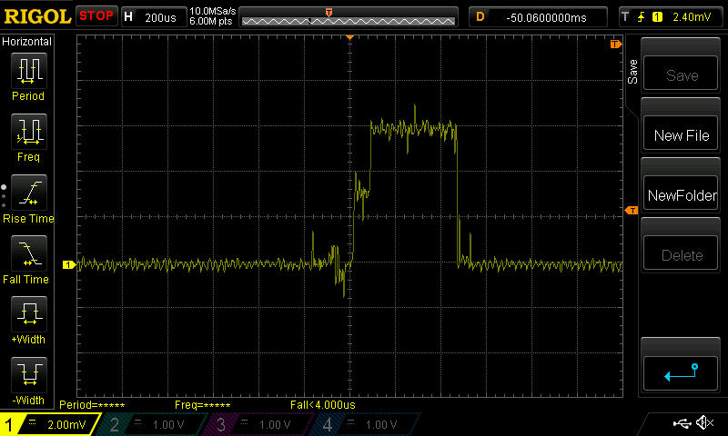
    I just switched to TBRH20 and wrote a simple loop to send a packet every 100ms, and to not be listening inbetween. Apparently the default behavior for TBRH20 is to try 16 times to send the packet before giving up!

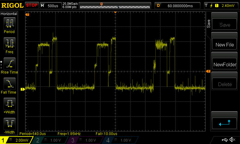
    As before, this is just one shot on the oscilliscope. I'm zooming in on each successive screen by adjusting the time base. I did the measurement on one of the modules with a "genuine" Nordic chip.

    TBRH20_1.jpg
    TBRH20_2.jpg
    TBRH20_3.jpg
    TBRH20_4.jpg

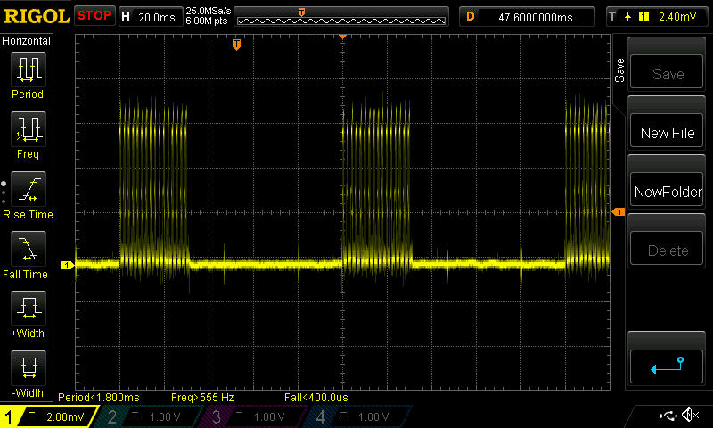
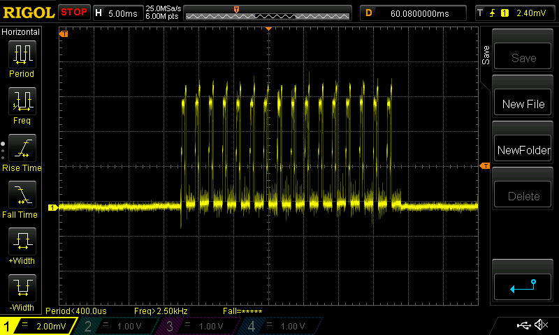
    I would guess that in this case TBRH20 is managing the retries in software on the Arduino rather than utilizing the radio chip, because the time between retries is much larger: about 1.5ms.

    BTW, I switched to a Mega2560 to do the testing, and, although I haven't yet investigated it, I think the new type of noise that's now evident is probably from the 5v and/or 3v voltage regulator. It doesn't obscure the view, so for now I'm not really concerned.


  • Hero Member

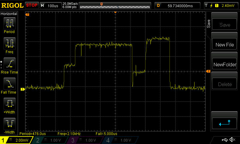
    Nailed it. If I explicitly turn ACKing off, then:

    noAcks.jpg
    noAcks2.jpg

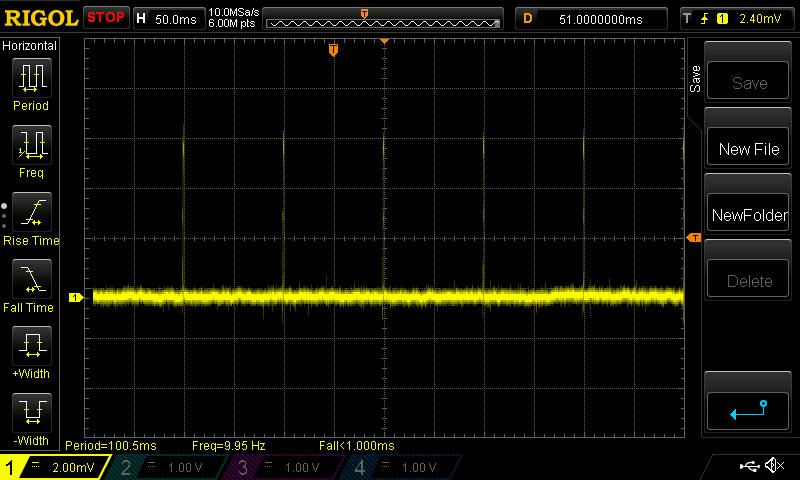
    What's shown is just a single transmit pulse at 100ms intervals, and with no RX current afterward, as would be required if an ACK was being listened for.

    Bottom line: now that the anatomy of the Tx current is known, it should help spot and identify clone chips by comparing their Tx current waveform against that of chips known to be genuine.


  • Hero Member

    You've nailed it indeed.

    I'm guessing that the first peak on the blob chips is higher because it has higher RF output as well.

    If you set bit 0 of register 6 to a 1 on the Blob (unused on the nRF24L01+), and if this chip is a Si24R01 or derivative, it will switch from +2~3dBm to +7dBm RF output, and probably draw even more power.


  • Hero Member

    @TD22057 said:

    I'm seeing similar results with my radios. ... The two types seem to be able to talk to each other OK but if set two modules at opposite ends of the house (with 2 exterior walls in between as well), the cheap modules still connect and the genuine ones don't. I'm assuming this is similar to what you're seeing with the real modules having a lower transmit power.

    My hypothesis: The blob units have more transmit power (perhaps being Si24R01 or related) and thus a higher first peak, but perhaps no better receive sensitivity.

    If so a blob to genuine would have at least as good a range as blob to blob, and a genuine to blob would have similar range as a genuine to genuine.

    Of course testing that may involve a one way transmission, where we check for lost packets on the receive side (without expecting a round trip).

    If however the blobs have managed to beat the genuine receive sensitivity, then they are really hot stuff!


  • Hero Member

    @Zeph said:

    @TD22057 said:

    I'm seeing similar results with my radios. ... The two types seem to be able to talk to each other OK but if set two modules at opposite ends of the house (with 2 exterior walls in between as well), the cheap modules still connect and the genuine ones don't. I'm assuming this is similar to what you're seeing with the real modules having a lower transmit power.

    My hypothesis: The blob units have more transmit power (perhaps being Si24R01 or related) and thus a higher first peak, but perhaps no better receive sensitivity.

    If so a blob to genuine would have at least as good a range as blob to blob, and a genuine to blob would have similar range as a genuine to genuine.

    Of course testing that may involve a one way transmission, where we check for lost packets on the receive side (without expecting a round trip).

    If however the blobs have managed to beat the genuine receive sensitivity, then they are really hot stuff!

    @Zeph I'm pretty sure the blob modules are using the RFM75 die because the above mA and uA measurements appear to be a good match for the electrical specification on page 22 of http://www.hoperf.com/upload/rf/RFM75 Datasheet v1.0.pdf

    Makes me wonder if it would perform the same or differently if it were installed on the manufacturer recommended PCB along with all the recommended passive components, because you can buy proper RFM75 modules cheaper than "genuine" NRF24L01+ modules.


  • Look at this RFM75 module. It's got the blob. It sounds like a bad horror movie.

    http://m.ebay.com/itm/171874462905


  • Hero Member

    I've since learned that "COB Module" would be a more proper term, but I didn't know that when I started this thread. COB = "Chip on Board" The bare semiconductor die is wire bonded directly to the board. I don't know why, but apparently that's cheaper by what, a penny or two? Once that work is done, the epoxy goes on to protect it.


  • Hero Member

    @Zeph said:

    You've nailed it indeed.

    I'm guessing that the first peak on the blob chips is higher because it has higher RF output as well.

    If you set bit 0 of register 6 to a 1 on the Blob (unused on the nRF24L01+), and if this chip is a Si24R01 or derivative, it will switch from +2~3dBm to +7dBm RF output, and probably draw even more power.

    Based on the mA and uA measurements above, it's likely that the Addicore modules and the red modules are based on the Si24R01, because they are a reasonably good match for the electrical specifications on page 22 of the Si24R01 datasheet: https://www.dropbox.com/sh/kdenpdg60v5hzbd/AACG1jxQR71fkzX-U4a7CIh0a/SI24R1 (cn).pdf?dl=0

    That's all the modules that I have. I'm pretty confident everything has been properly ID'd. 😄


  • Hero Member

    @NeverDie said:

    @Zeph I'm pretty sure the blob modules are using the RFM75 die because the above mA and uA measurements appear to be a good match for the electrical specification on page 22 of http://www.hoperf.com/upload/rf/RFM75 Datasheet v1.0.pdf

    Could you see if they work on channels above 84? The RFM75 lists fewer channels than the nRF24L01+, which is probably for regulatory rather than technical reasons (the frequency band does extend further in another part of the spec). I would be curious to know if channel 125 works, for example.


  • Hero Member

    I previously tested the COB modules as working on channel 112, both with each other and interoperating with "genuine" NRF24L01+ modules.

    This is one of the areas where there's a disconnect between what the HopeRF website says and what the electrical specs on the datasheet I referenced above say regarding the RFM75. The website says it only goes up to 2.450Ghz or something, and the datasheet specs say it goes all the way to 2.5Ghz. I'm assuming the datasheet is right, not the website.

    The modules are cheap enough that I may order a couple, just to see if they perform a whole lot better when soldered to proper PCBs and the correct passives are used. It may be moot though if I decide to use RFM69x's instead.


  • Is it possible to use NRF24LE1 (L01+MCU) as simple NRF24L01+? Are there any of these LE1 modules fake too?

    Question inspired by this topic: http://forum.mysensors.org/topic/1774/introducing-mysensors-on-nrf24le1


  • Would it be possible that someone would create a sketch that would detect fake modules and warn about discrepancies? I would hate to spend more money on fake modules.


  • Mod

    @Avamander said:

    Would it be possible that someone would create a sketch that would detect fake modules and warn about discrepancies?

    Yes, but currently the 'scene' is not aware of a decent way to distinguish fake from real.
    As soon as we know how to determine this a sketch can be written.


  • Speed is one thing that can be tested, fakes are slower. Packet loss too. ACK with dynamic payloads too. Registers that exist only on fakes (the datasheet error one for example).


  • Mod

    @Avamander said:

    Speed is one thing that can be tested, fakes are slower.

    I suppose you mean the maximum bitrate possible?
    Most fakes will handle all nRF bitrates flawlessly.

    Packet loss too

    I have not seen any proof of differences in reception between reals & fakes.
    The construction & orientation of the module on which the nRF is mounten will IMHO mostly determine the transmission quality.
    I'd like to see an algorithm which reliably determines fakes from real using packet loss.

    ACK with dynamic payloads too.

    This is claimed to be a difference and it might be true for some modules, but all my fakes behave identical on-air compared with real nRF's (verified by sniffer)

    Registers that exist only on fakes (the datasheet error one for example).

    Again, the web is full of contradictory reports...

    Most of these fakes are very good copies and I doubt if anyone can find a software-only solution to determine real from fakes reliably.
    Our best bet would be to create an accurate power fingerprint of a genuine module and compare the fakes to it -- that's the only more or less consistent difference I've seen so far.

    Remember that even Nordic will perform an X-Ray on a suspicious nRF to be absolutely sure if its genuine or not.

    That said -- be my guest and try to create a sketch. The scene will thank you for it if you succeed 😉


  • Hero Member

    The power fingerprint seems to work very well. I suggest you use that. The work is already done (see above).


  • Lots of useful info here, thanks everyone for the hard work!

    Based on the findings, are the NRF24L01+ modules linked on the shop page still the best recommendation? Is it worth adding the cap as a required part of the setup to increase reliability?

    Just received 20 units from the vendor linked through aliexpress and am working through issues which appear to be related to the radios (not using cap's currently)

    Starting...
    find parent
    send: 255-255-255-255 s=255,c=3,t=7,pt=0,l=0,sg=0,st=bc:
    find parent
    send: 255-255-255-255 s=255,c=3,t=7,pt=0,l=0,sg=0,st=bc:
    find parent
    send: 255-255-255-255 s=255,c=3,t=7,pt=0,l=0,sg=0,st=bc:
    find parent
    send: 255-255-255-255 s=255,c=3,t=7,pt=0,l=0,sg=0,st=bc:
    find parent
    send: 255-255-255-255 s=255,c=3,t=7,pt=0,l=0,sg=0,st=bc:
    sensor started, id=255, parent=255, distance=255


  • Hardware Contributor

    @nftrix I'm using nRF24L01+'s for all of my applications at the moment still with no issues at all. They are running perfectly smooth, without interference off of anything. I personally just soldered my caps straight onto my radios when they arrived, before even testing them. If you're not restricted by space, just solder/attach them straight to the module as they arrive through your door.

    As with your issue that you have shown, i would say give the cap a try before jumping to conclusions as it appears that its sending out a message asking the gateway to reply back with a connection package but its not finding it (I may be wrong, but that is what i see there). Give it a try and report back with your findings 🙂


  • Hardware Contributor

    @nftrix Another way to deal with the fact that some nrf24l01+ modules can not find the gateway, is by reducing the transmit powerlevel. Some of these modules "scream" so loud, that the receiver on the gateway gets a distorted signal and fails to recognise a proper packet.
    In my house I have had to reduce the transmit levels of most of my modules, and as a result they now all connect to the gateway without any caps.
    The NRF24 on the gateway does have a potent powersupply and caps on the board it is mounted on, but my sensornodes do not need it.


  • @samuel235 @GertSanders thanks for the feedback. I'm picking up some caps from the store today and will try them out. As for the power settings, I've been adjusting the data rate settings between 250kbs, 1 and 2Mbps but am seeing the same results. If the caps don't fix the issue, i'll start another thread to work through the problem, don't want to hijack this thread.

    Just wanted to confirm that the findings here did not make the NRF's on the store "not recommended" or anything.


  • Hardware Contributor

    @nftrix said:

    Just wanted to confirm that the findings here did not make the NRF's on the store "not recommended" or anything.

    Most definitely not. They're more than recommended from most of us i think, from a quick look at the forum topics anyway.


  • Hardware Contributor

    The speeds settings (250k, 1M, 2M) are not the same as the power settings (Low, Med, High, Max).


  • @NeverDie
    I just compiled and uploaded your code to two uno's and all I am getting is
    OTA datarate set to 1Mbps. Transmit Power set to Maximum.
    rf_setup = 111
    Sending...

    how long does it take to get any output on the serial monitor?


  • Hero Member

    @parachutesj
    I was using 3.3v pro mini's, not uno's. Maybe you have a level shift problem.


  • @NeverDie
    ok, thank you. using Nano's work. getting 13% loss is not too bad


  • Hero Member

    @GertSanders
    In your experience, which of the SMD modules have you found work the best?


  • Hardware Contributor


  • Hero Member

    @GertSanders
    Are you happy with their performance? I imagine the answer is yes, but I thought I'd ask just to be sure.


  • Hardware Contributor

    @NeverDie
    I am, there is one on my front door, which needs to cross two floors to get to the gateway in the attic. Bleeps every time. Range (as far as I can see) is close to the classic small version.
    Good enough for me.


  • Hero Member

    @GertSanders
    Thanks! I just now ordered some of the same SMD modules using the link you provided. The last time I looked into this (at the start of this thread), it seemed as though just about everyone was using a different mix of modules and platforms. and that made an apples-to-apples performance comparison quite difficult. However, this time around, I'll be running the same modules as you on the same hardware platform as you (well, nearly so, assuming I build it to spec), and so if it works well for you it presumably should work the same for me too.


  • Good morning together, iam very new in mysensors forum, so this is my first post, and i have a question: a want to buy these NRF's can somebody tell me if they are okay?
    https://www.amazon.de/Kuman-nRF24L01-Wireless-Transceiver-Compatible/dp/B01BVAAASY/ref=sr_1_fkmr0_1?ie=UTF8&qid=1464158231&sr=8-1-fkmr0&keywords=nordic+nrf24l01+10pcs

    Thank you!


  • Hero Member

    @HarrySteff There is no way (that I know of) to determine in advance if the modules work according to specification. Even different lots from the same supplier can vary in performance. I have a 5 out of 6 succes rate with different suppliers.


  • Thank you @AWI i will Order them to Test...


  • I have had an excellent experience with the SMD version. I cannot say if there are different versions of it, but all transceivers I purchased from different suppliers work flawlessly.


  • Hardware Contributor

    @alexsh1 Do you have any links for the SMD versions that you can recommend, i'm wanting to try these now. Thanks.


  • @Samuel235 these were the ones I ordered last time. Tested all of them and very much pleased

    Look what I found on AliExpress
    http://s.aliexpress.com/ZfArmaqe


  • @alexsh1
    At which settings do you use them?
    I have those http://www.aliexpress.com/item/10PCS-LOT-NRF24L01-wireless-data-transmission-module-2-4G-the-NRF24L01-upgrade-version/1593276910.html
    And not so happy as they seem to loose connection from time to time over distance of 4-5m
    I set them at 250 and have good power & caps attached

    At least the chip seems to be original but not soldered very well


  • @parachutesj I'll be honest with you - so far I had more luck with the SMD version which works 20m+ across a few walls than with a regular transceivers. Sometimes one needs to invite a shaman to make sure that nrf24l01+ works.

    I have 250kb rate on all nodes + caps. All works fine. With some regular nrf24l01+ I had issues with some batches and claimed money back successfully after ditching the whole batch. Luckily, this bad batch has not been working at all rather than working intermittently.

    Just a suggestion - did you change any settings on your gateway nrf24l01+? I'm using the amplified version by the way feeding it through AMS1117 LDO


  • @alexsh1 said:
    I switched to ampliefied nrf24 with antenna from the link in the shop but this seemed to make it even worse. It was powered externally and tried to shield it with no real luck. I ordered some shielded ones from ICstation which are still in customs process and hope to get them by the weekend. I also ordered a bunch of others and I will try which are the best for my operations.
    Just today I hade the closest node getting stuck. I wasn't able to send any from controller to the node. After triggering a signal from the node (it is a rollershutter) it came back to live and was able to send via controller again. Quite annoying...
    Maybe I need to try some different caps and voltage regulators, actually got "good" ones from my local electronics shop.


  • Hero Member

    Do the amplified modules simply always function at full amplification, or is there a code change that's needed to adjust the Tx power? Towards the start of this thread I tried some amplified modules from ICStation, but I was hugely disappointed with them. In fact, I don't think I saw any improvement at all, which greatly contradicted the experience that some others appeared to be getting. At least at that time, though, there was no real guidance on how to use them effectively, and so maybe I wasn't driving them right. Maybe there's more information now.


  • @parachutesj What settings do you have on your gateway please?


  • @NeverDie In MyConfig.h there are settings:

    #define RF24_PA_LEVEL 	   RF24_PA_MAX
    #define RF24_PA_LEVEL_GW   RF24_PA_LOW
    

    The second one is for the amplified version (RF24_PA_MAX can used)

    Please check out this:
    https://forum.mysensors.org/topic/653/nrf24l01-pa


  • @alexsh1 I have this

    #define RF24_PA_LEVEL_GW RF24_PA_MAX
    

    on the GW
    Maybe I need to try RF24_PA_HIGH if it changes anything. However still waiting for the "good" radios to arrive


  • @parachutesj First things first:

    1. Good transceiver
    2. decent 3.3V feed
    3. settings MAX or HIGH etc


  • All of my ~20 NRF24's from 5 different dealers are consuming 15mA when the node is in sleep mode. Is this really a radio problem, or a software problem?

    By pulling out the radio, current drops below 1mA.

    • 2.0.0beta binarySwitchSleep sketch
    • My-Slim-2AA-Battery-Node
    • bootloader from My-Slim-2AA-Battery-Node OpenHardware source
    • BOD disabled by fuses, 1MHz internal
    • current messuered with Fluke multimeter

  • Hardware Contributor

    @rollercontainer
    Have you tried to measure the power consumption whithout radio, and just putting the atmega328 in deep sleep (sleep(0)) ?
    Normally you should then see something less then 10 micro amperes.
    If the node still consumes around 1mA in this situation, then I would advise to look at the soldering and the other components.
    With BOD disabled, an atmega328p in deep sleep consumes around 1 micro Ampere,.
    Did you use the atmea328P version or the standard atmega328 (without the P) ?


  • @GertSanders I wrote "below 1mA" because I couln't recal the exact value, just for pointing to the relation between radio consumption and idle without radio.

    I've got 328P from Reichelt.de and messured again withoput mysensors.h and with SLEEP_MODE_PWR_DOWN. The multimeter reads 0,09mA at 60.00mA range set. Looks valid to me.


  • Hardware Contributor

    @rollercontainer
    If you are using the internal pull up resistors on the switch input pins, then indeed you will get something like 30-60mA.
    That is why we use external pull up resistors for switches when we want to go for lowest possible power consumption.

    The internal pul up resistors have a value around 30K-45K (there is some variation). The pull up resistors I use are 1MOhm, this cuts the current consumption by two factors.


  • Hero Member

    @rollercontainer : you cannot get a proper measurement using only just a multimeter. Fluke or no Fluke, it just isn't going to happen. Lookup "burden voltage." Enough said, as this has been covered in-depth all over the place.


  • You both missed the point. My problem isnt the idle consumption yet. My problem is, that all the radios consume too much. Is there a way to get it down, or do I have to dump them all?


  • Mod

    @rollercontainer are you using the Arduino SLEEP_MODE_PWR_DOWN ? If so, the radio will still be active because the Arduino library isn't aware of the radio. Use the MySensors gw.sleep instead.


  • Holidays are over, back to work ^^
    To clarify it again:
    First I tried with complete 2AA slim node, several radios, sensor and the default binarySwitchSleep 2.0.0beta sketch. (15mA)
    For the second run: NO radio, sensor or MySensors.h were used. Therefore I wrote a minimal sketch with SLEEP_MODE_PWR_DOWN to ensure that the AVR is going to sleep mode. (< 0,1 mA)
    This leads me to the conclusion, that every of my ~20 radios is faulty. Are there any ways to prove this?


  • Hero Member

    @rollercontainer
    Sure. Buy a "known good" radio for comparison.


  • Hardware Contributor

    Are the radios in the store here known as good and working now? I know we had issues with a bad seller previously, has this been sorted now?


  • Hero Member

    @NeverDie are you sure the node enters deep sleep? The current you measure is typical for a non sleeping radio. Main problems I have with the bad radio's is that these stay awake until they "found a parent". Where do you live? If you drop me a message I can send a tested one.


  • Hero Member

    @AWI said:

    @NeverDie are you sure the node enters deep sleep?

    I don't recall. It's been a while since I ran the tests. Presently I'm using RFM69's, which draw about 100na when sleeping, but at some point this summer I hope to revisit using NRF24L01's. I've already received the SMD modules that Gert Sanders is using, and I'll be giving them a try on the boards he designed, so the odds are favorable that I'll be getting the same or similar results. I received the boards from the fab, so after I receive the remaining parts I'll do the assembly.

    Earlier in this thread it was advised to order direct from Itead, on the grounds that they were manufacturing them. So, going directly to a reputable source might increase your confidence of getting what's advertised. Frankly, these things are cheap enough that I'd suggest going to several different such sources and then vet what you get using an oscilloscope. I did that earlier in this thread, and you can compare your results with the screenshots I posted to ID your chip. Of course, that by itself doesn't guarantee that the antenna was properly matched, which is why I think comparing the ranges of different modules from different sources is probably still a good idea. Even if the components are right, the dielectric of the PCB could throw off the match, and you won't know that just by looking at it.


  • Hardware Contributor

    Unfortunately i don't have an oscilloscope at the moment. So i have to just test them in the circuit as intended to be used.


  • @NeverDie I already bought these ~20 radios from 5 different dealers...
    @AWI I am not sure, therefore I am asking here. But what more can I do? I am using a default sketch with only this modification:

    #define MY_NODE_ID 70
    #define MY_PARENT_NODE_ID 0
    #define MY_REPEATER_FEATURE false
    

    The node is useable, so it sends reed contact changes to the mqttClientGateway which sends it to my raspi. Is the static method preventing the node from deep sleep?

    I live in northern germany. Thx for the offer. But I dont really believe, that all radios are faulty by now.


  • Hero Member

    @rollercontainer
    I still suspect either a configuration or a measurement error. I suggest you photograph in detail everything you're doing and post it. If you're overlooking something, maybe somebody will spot it. Otherwise, there's just not much to go on.


  • I setup a new Arduino IDE 1.6.9 portable with MySensors 1.5 and flashed a standard 8MHz bootloader with BOD off.
    Idle current is nearly unmessureable by my MM, showing only 0,01 mA at 60,00 mA range.
    Next step is to get a 1MHz bootloader to work with low current.

    Thx for your words, guys.


Log in to reply
 

Suggested Topics

  • 87
  • 10
  • 2
  • 9
  • 7
  • 7

0
Online

11.2k
Users

11.1k
Topics

112.5k
Posts