My own board (50mm x 30mm)
-
Next variant. Less flexible, but flexible enough. Boardsize now 50x30mm
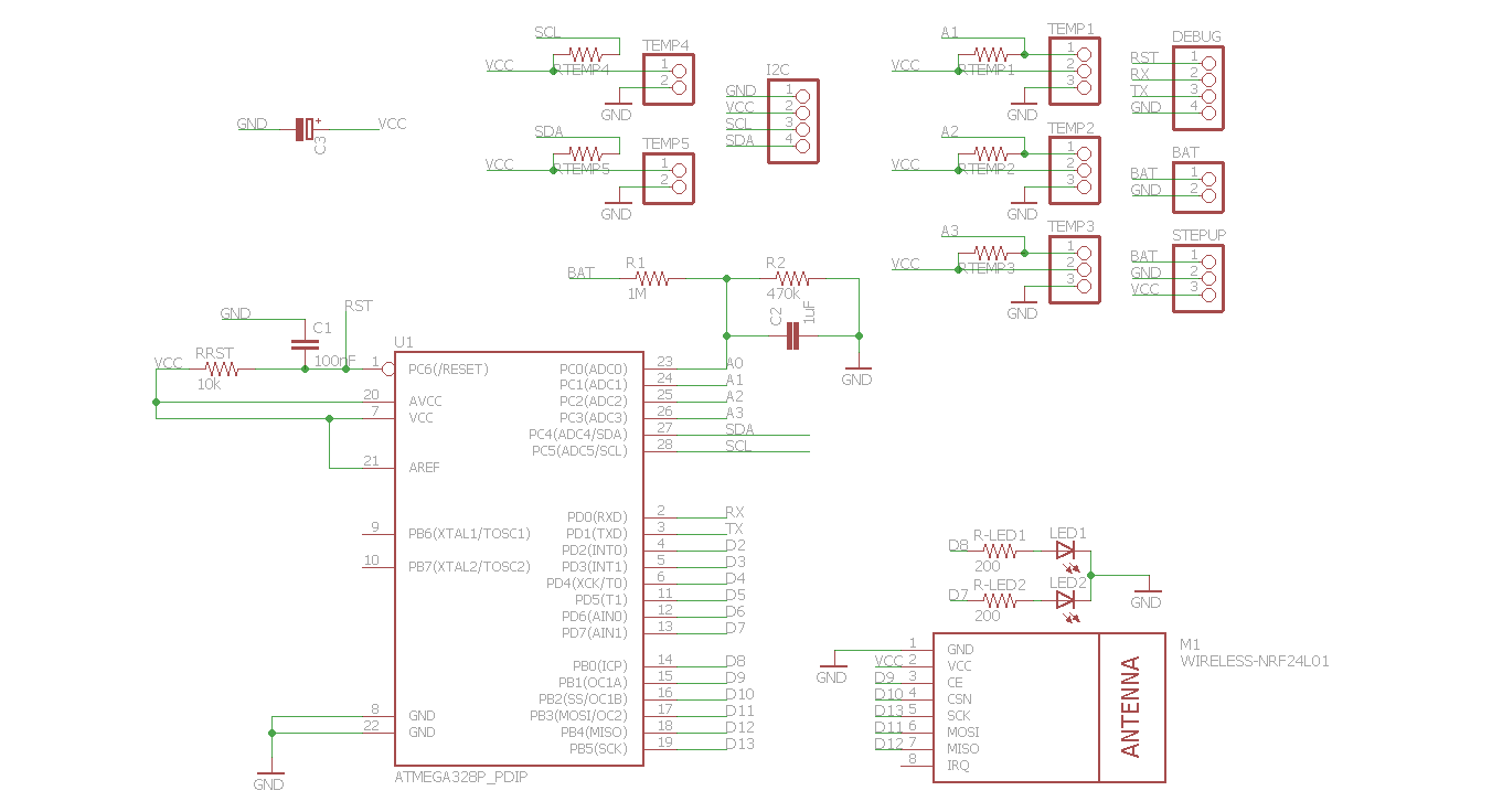
It's only one pcb now and you can connect- 5x sensors (digital or analog)
- 1x I2C and 3x sensors (digital or analog)
Step-up can be soldered to the bottom.
What do you think?
-
hi Andreas,
What is the intention of TEMP4 and TEMP5 connectors ? I see that you pull up SCL and SDA, but all these connectors can do now is give VCC and GND on pin 1.
For TEMP1->3, it depends on how the sensor actually works. With Light Dependant resistor there is no issue. For other sensors (TMP36), a resistor pulling up to VCC would be a problem. A switch would be OK between pin 1 and 3 (GND) of those connectors. What is the usecase ?
I have a atmega1284 based design, which is not yet shared on OSHPark. The version I made has the NRF24 connector in the wrong direction (but this is still useful). However, I can not close the case with the NRF24 in place. It was made for a Hammond 1593N case (the transparent blue type, very cool):
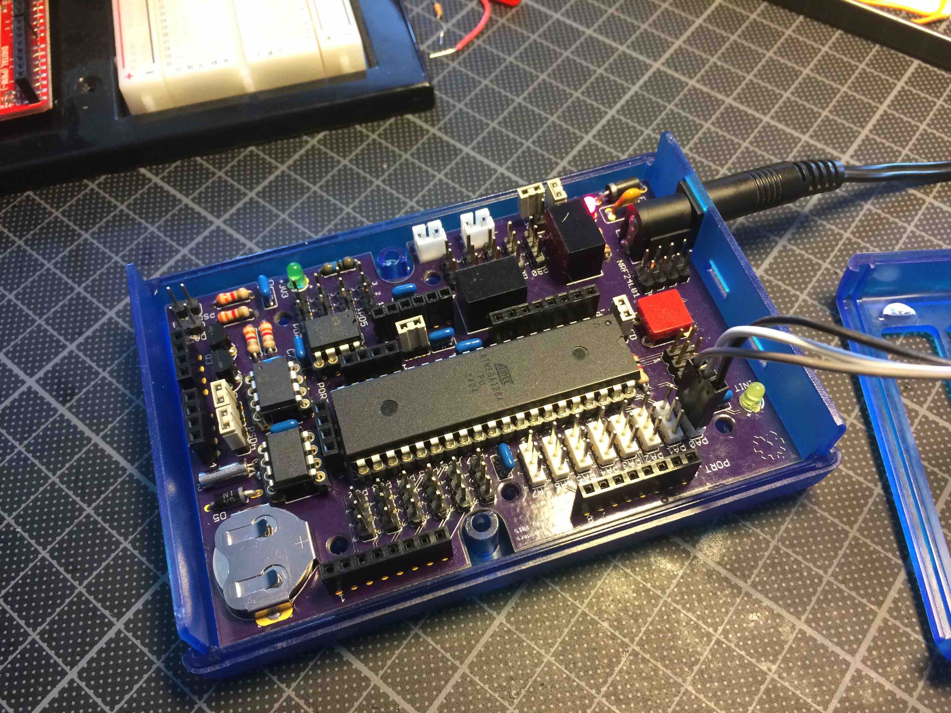
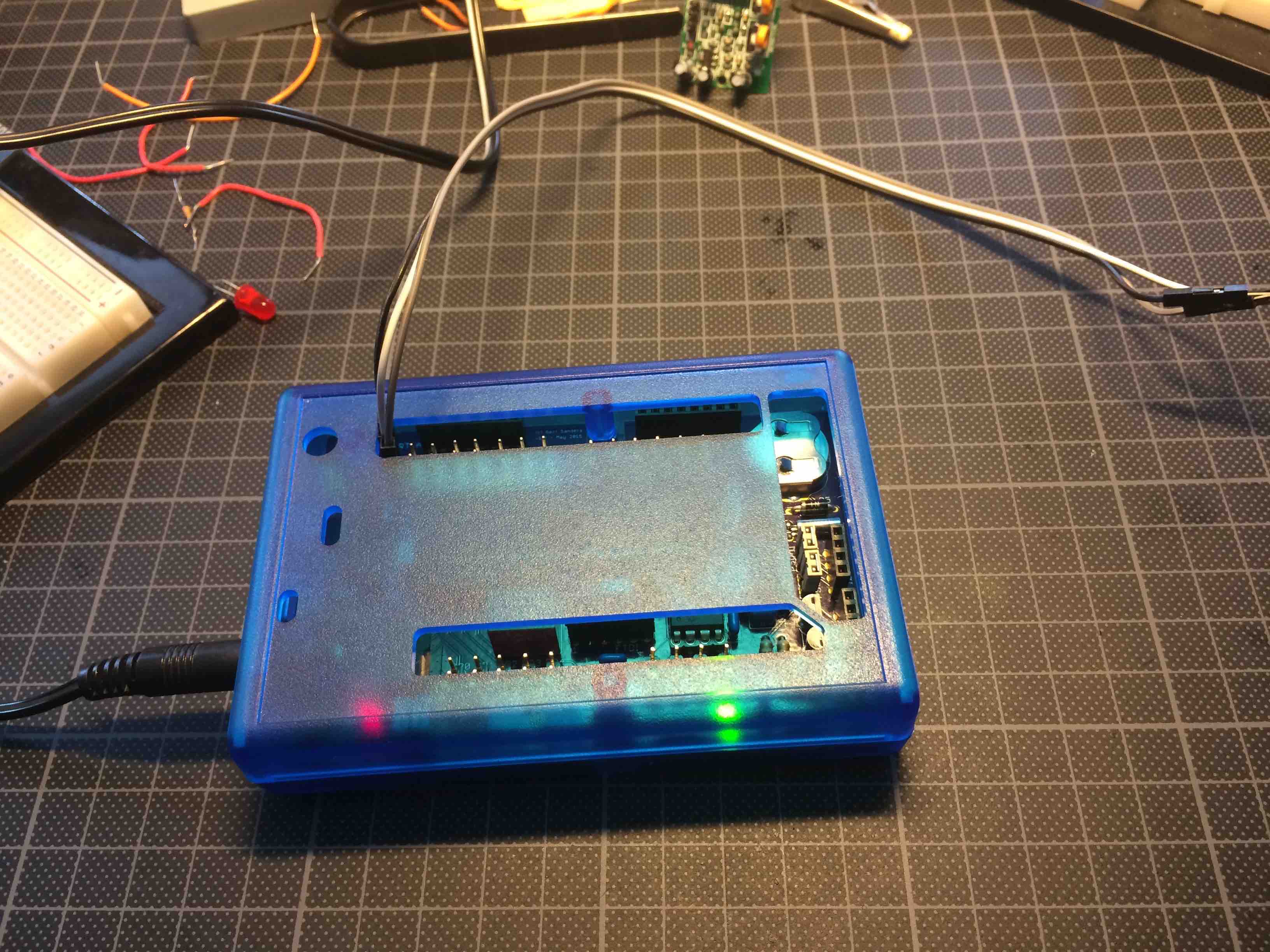
I used the case for the Arduino Due (bought this from Mouser).
I now corrected the orientation of the NRF24 connector but this not put this on OSHPark, because I can live with the mistake I made. Many ports on this one. But only works on 6-24V input. The power converters are from TRACO (1 for 5V, 1 for 3V3). It has 64KB EEPROM and RTC. Level converters for 5v->3V3 on I2C (so 2 I2C ports actually) and most pins are brought out together with 5V and GND.
The point here is that adding resistors to the three pin connectors is not really necessary. But it is nice to have signal-VCC-GND on three wires each time.
I think I will order the 1593K case next (to see what can be done with that), nice little box. -
@Andreas: Very impressive CNC machine !!!
-
Hi Gert,
thx for the cnc-flowers :D
Sensors
I thougt about the different nodes i will have later. The biggest node will have 5x DS18B20 - so i really dont need more than 5 "ports" to connect sensors. I changed them to the analog-pins of the arduino, because i can use them as digital and analog ports too...
Temp4 and Temp5 can be used as I2C ("horizontal") OR as Temp4 and Temp5 for DS18B20 ("vertical"). See top left corner of the board. I think it is very flexbile to not solder the resistors (disconnect VCC) or to solder a wire instead of the resistor (vcc to pad). In this way i can connect PIRs, DS18B20, Analog-sensors and so on....i just solder the parts i need for the sensors...
Only thing: I cannot use I2C AND Temp4 / Temp5 at the same time, because A4 and A5 are SCL and SDA too....
I hope you understand what i mean and try to reach...Btw: Jumper-pins are not a must, if i want, i connect the sensors via wire to the pads, or solder them onto the pads directly....
Greetings
Andreas
-
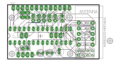
A 3D view of my lastest board :+1:
Tool used: http://mayhewlabs.com/3dpcb
So cool to see a 3D render, very fluid when moving around :-)
-
Hi,
3d-view is really nice. I dont know why, but my gerber files dont work. Board is BIIIIIIIGGG and without holes :(
I asked in the hardware-forum, if there are any errors in my design. (http://forum.mysensors.org/topic/2042/errors-in-pcb-design)
I must finish this and order my boards now ;) Otherwise i will never find an end....
-
Getting close to final layout myself ....
-
Hi,
i thougt a long time about placing such a booster on the pcb. Its quite difficult to find a good(!) booster. Lots of the cheaper booster draw a lot of current (quiescent current) - like the one behind your link. I tested only 2 until today.
This one: http://www.exp-tech.de/pololu-3-3v-step-up-spannungsregler-u1v10f3?gclid=CPmll6rH0ccCFRI6Gwod884Lxg
and this one: http://www.exp-tech.de/sparkfun-ncp1402-3-3v-step-up-breakout-prt-10967?gclid=CPCv55_H0ccCFUu6GwodKDUHwACurrent consumption differs approx 30uA between those 2 (red 70uA, green 100uA in sleepmode with sensors etc)...
Did you check current-consumption of your booster?Actually i am changing the board size to 50mmx24mm - its a lot cheaper to order from fusionpcb (seeedstudio)...
Thats a lot.
Greetings[▲QUICK EDIT]
Something like this? Booster soldered vertical....In this way you must select with the solder jumper how to power the board (battery direct or via booster)...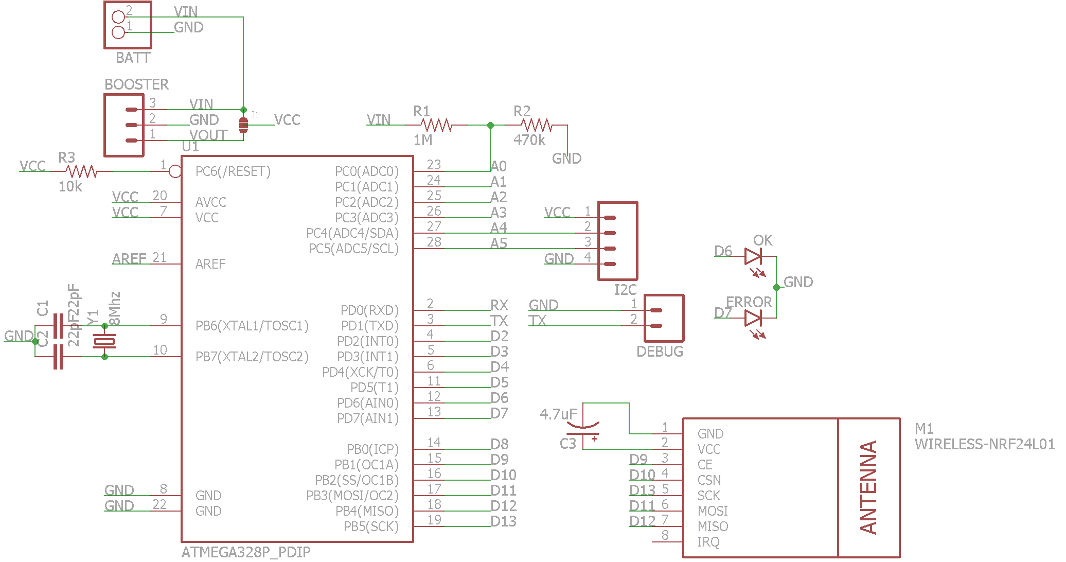
@ahhk said:
Hi,
i thougt a long time about placing such a booster on the pcb. Its quite difficult to find a good(!) booster. Lots of the cheaper booster draw a lot of current (quiescent current) - like the one behind your link. I tested only 2 until today.
This one: http://www.exp-tech.de/pololu-3-3v-step-up-spannungsregler-u1v10f3?gclid=CPmll6rH0ccCFRI6Gwod884Lxg
and this one: http://www.exp-tech.de/sparkfun-ncp1402-3-3v-step-up-breakout-prt-10967?gclid=CPCv55_H0ccCFUu6GwodKDUHwACurrent consumption differs approx 30uA between those 2 (red 70uA, green 100uA in sleepmode with sensors etc)...
Did you check current-consumption of your booster?Actually i am changing the board size to 50mmx24mm - its a lot cheaper to order from fusionpcb (seeedstudio)...
Thats a lot.
Greetings[▲QUICK EDIT]
Something like this? Booster soldered vertical....In this way you must select with the solder jumper how to power the board (battery direct or via booster)... Hi ahhk,
Can You share brd files for this version? Thanks.
Maciej -
Hi,
sure i will share the brd-file and schemativ. No problem. But let me first build one working sensor. I think i will order the pcbs this weekend, because this looks good too =>
-
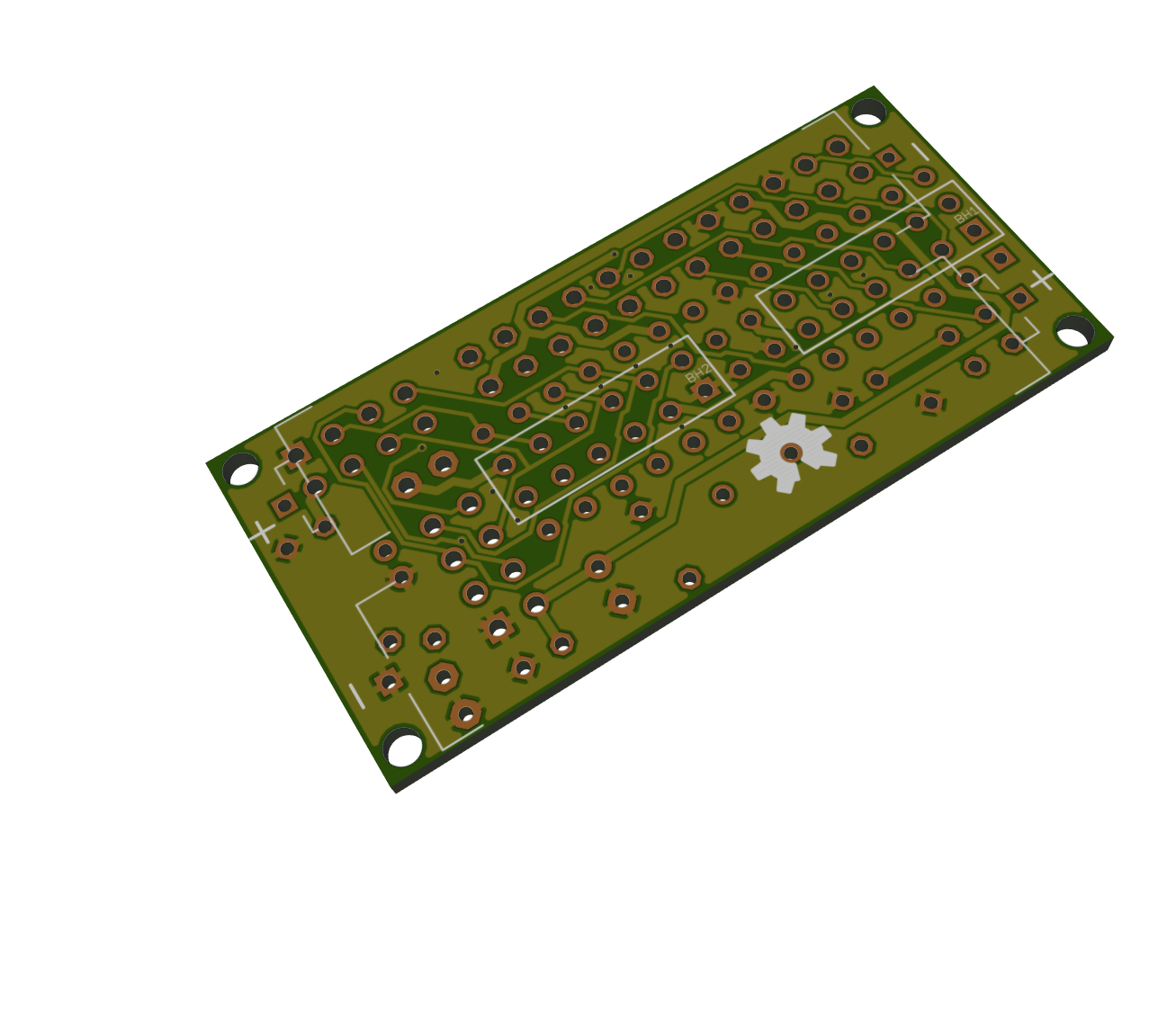
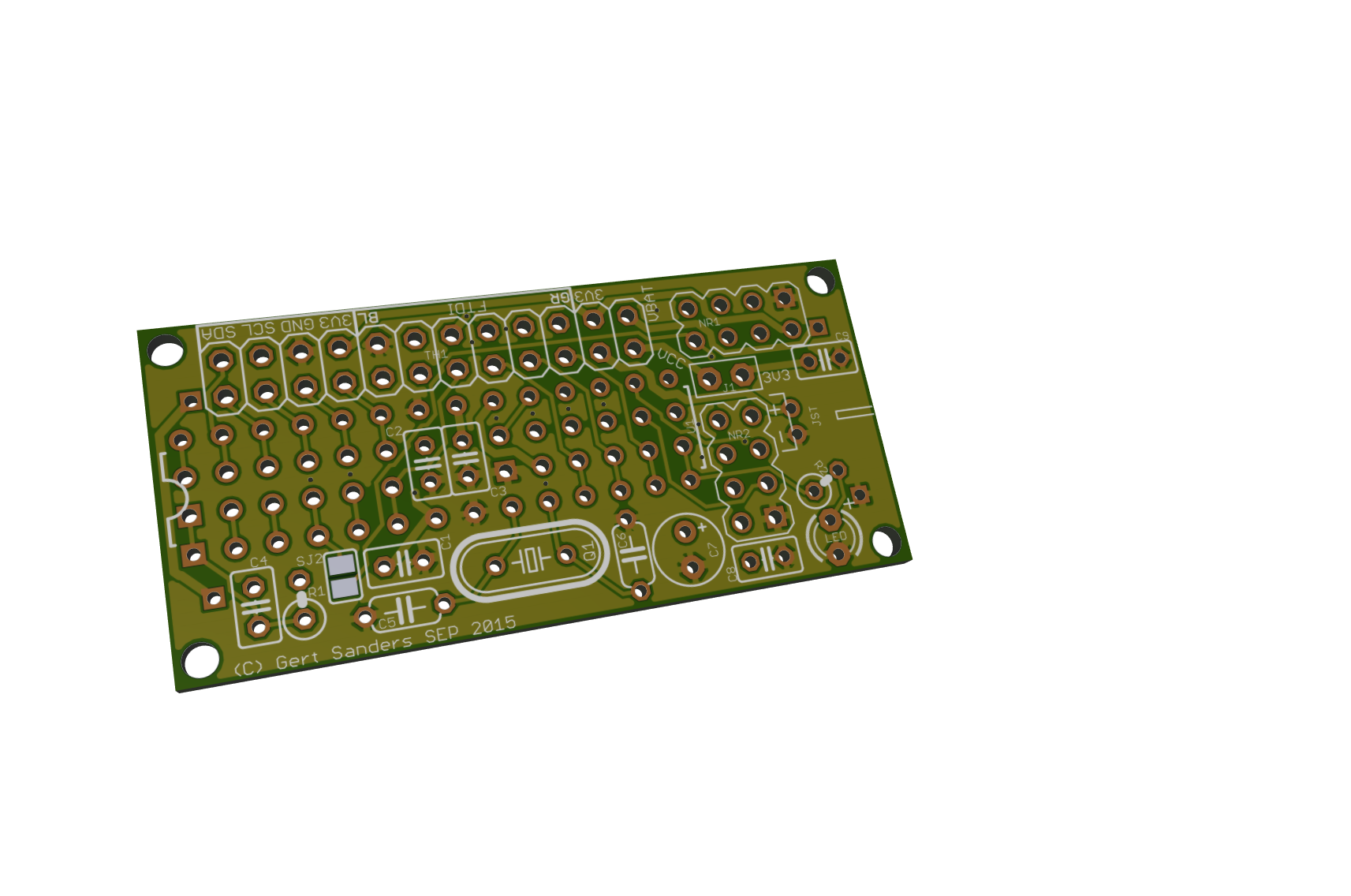
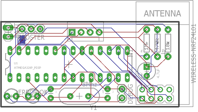
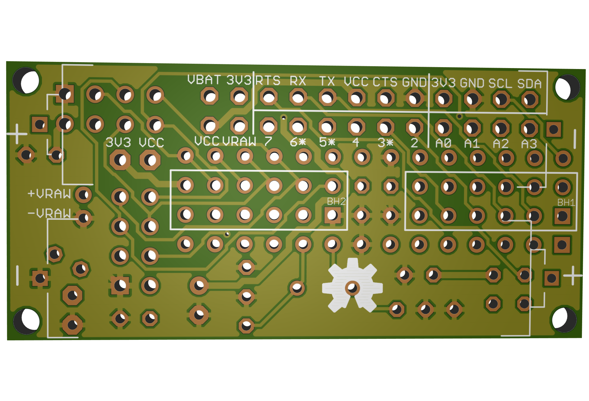
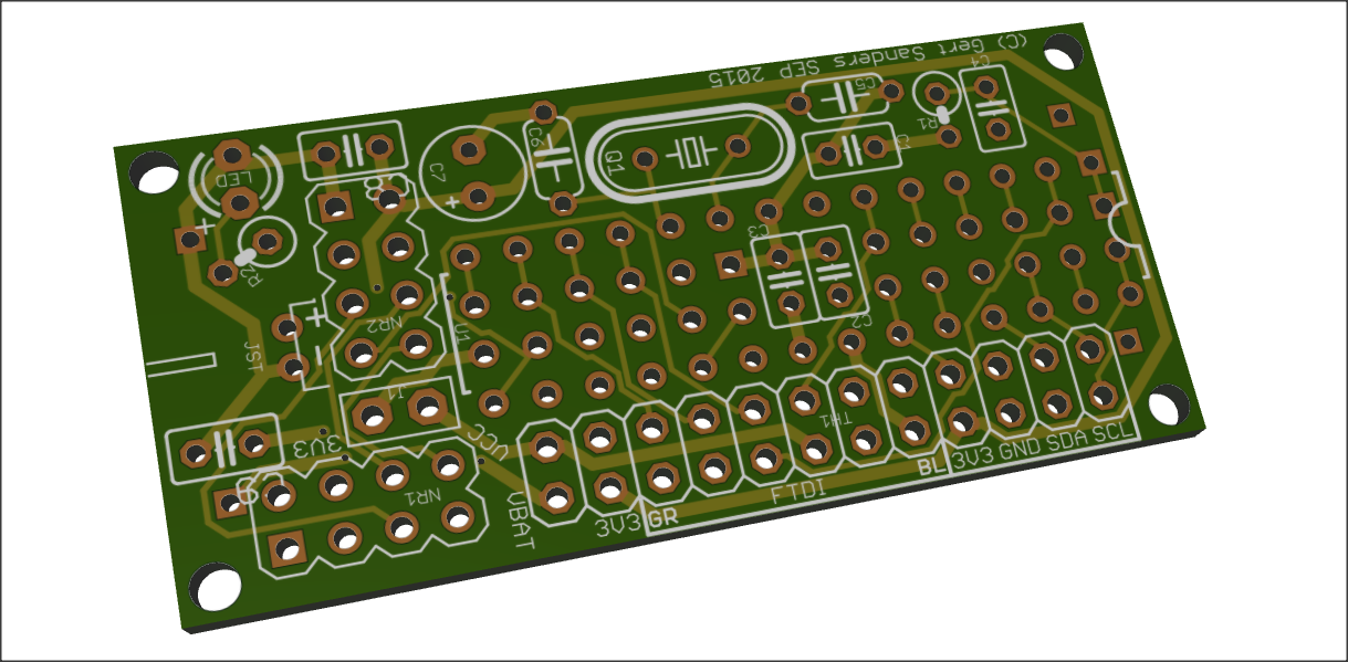
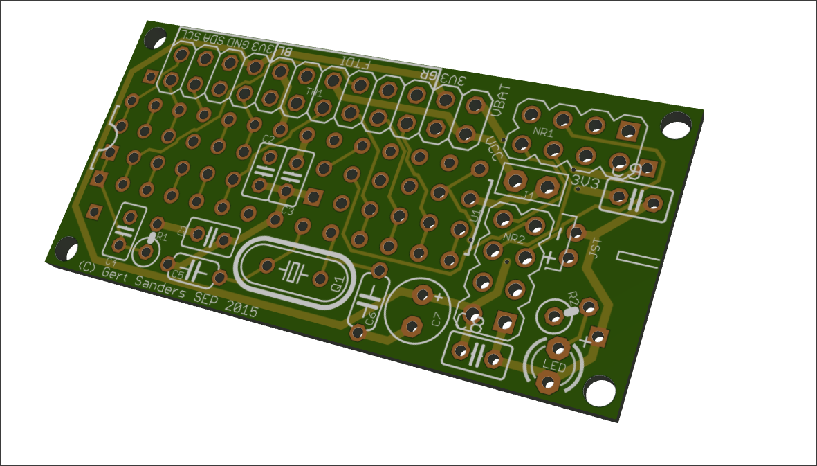
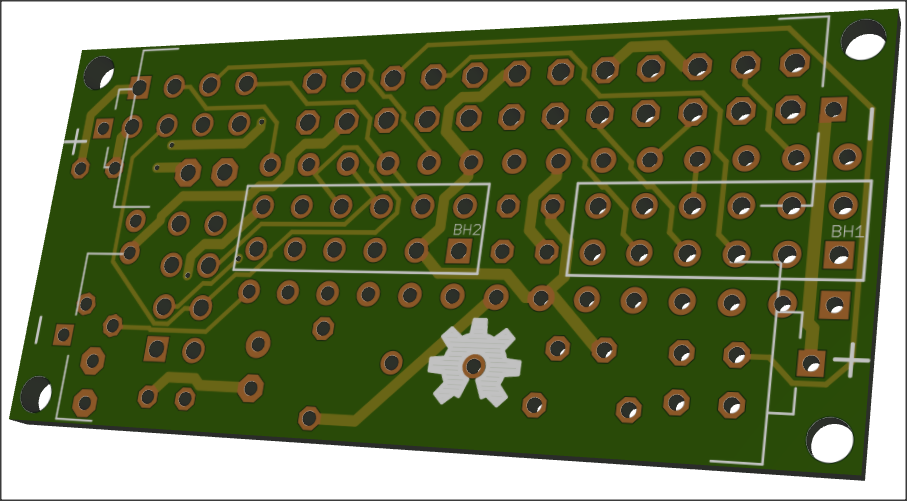
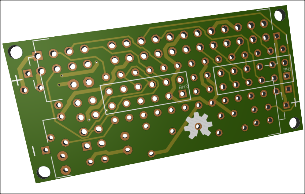
Done, this will be sent to the PCB makers:
Top:
Bottom:
-
each boards are nice, good work :wink:
-
PCBs are ordered (shenzen2u)....i am very curious about it :)
-
Update: PCBs are shipped via express... :dancers:
-
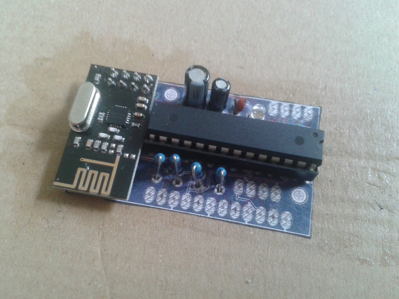
Update: this arrived in my mail today:
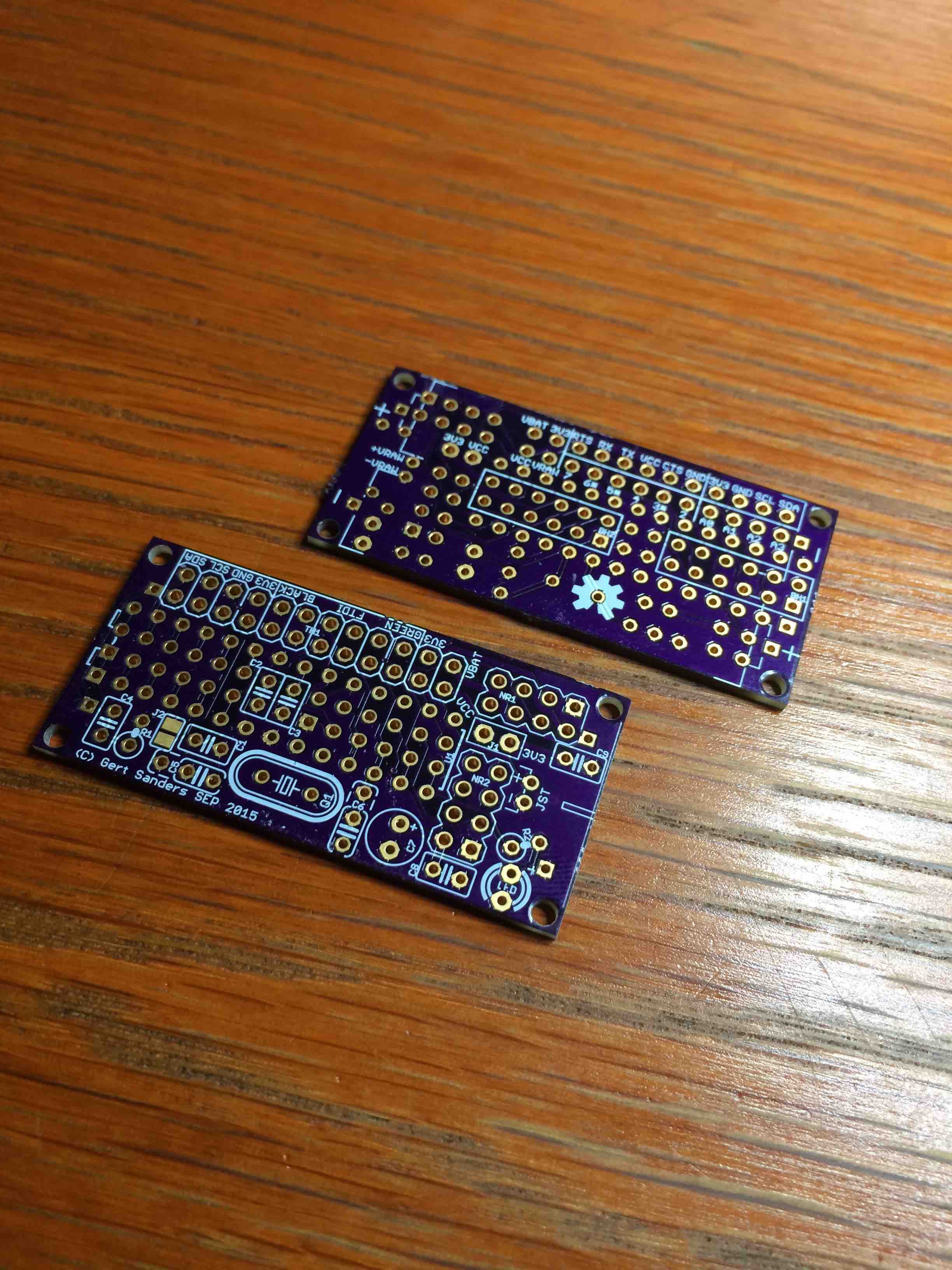
I also ordered a set from DirtyPcbs, which were ready lastweek monday, but are still on their way to me.
Assembly starts tomorrow :-) -
ok, great :) Lets how they look ready....
-
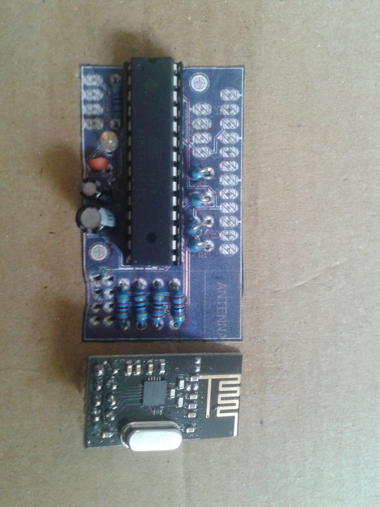
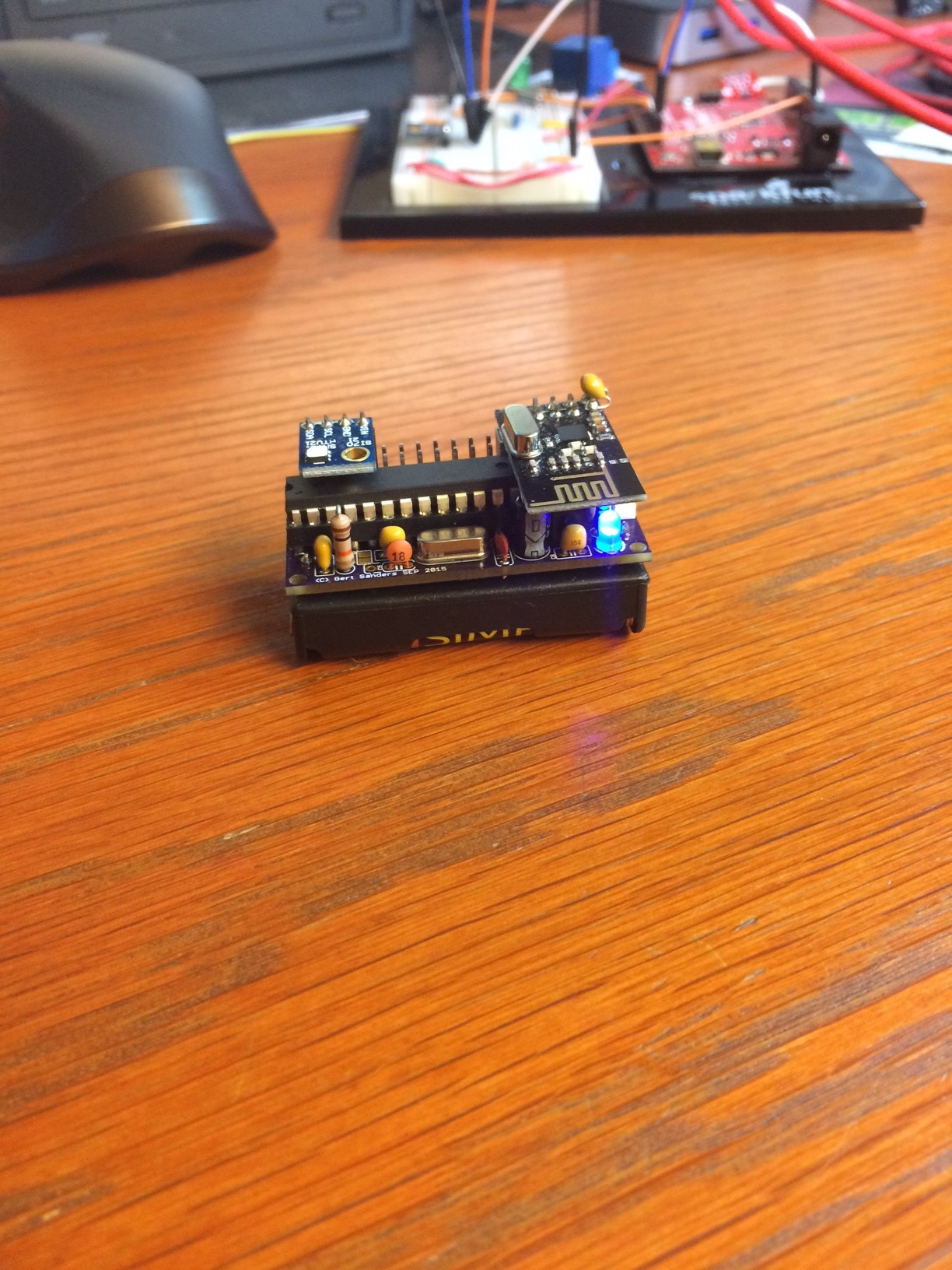
Here is version 2 of my sensor:
-
This post is deleted!
-
Maybe its better to open a new thread for this question? ;)
-
Just realised this. Indeed, I will start a new topic.
-
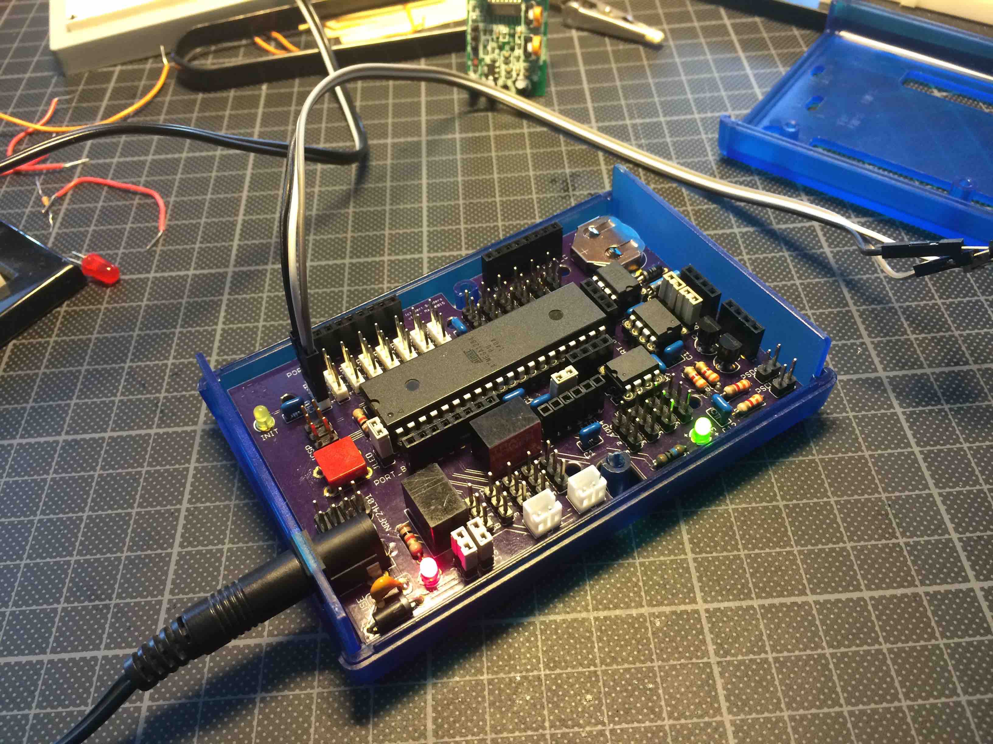
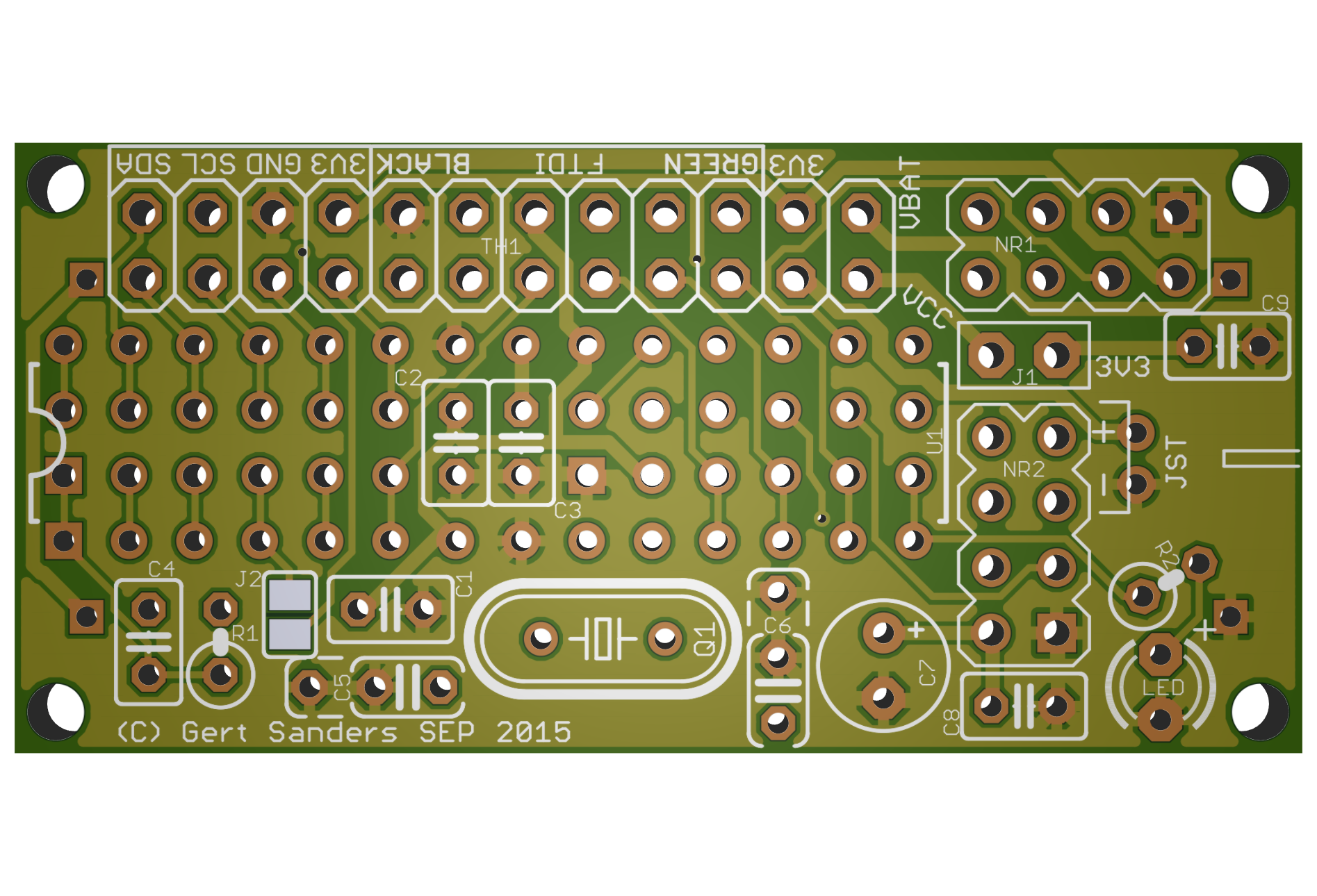
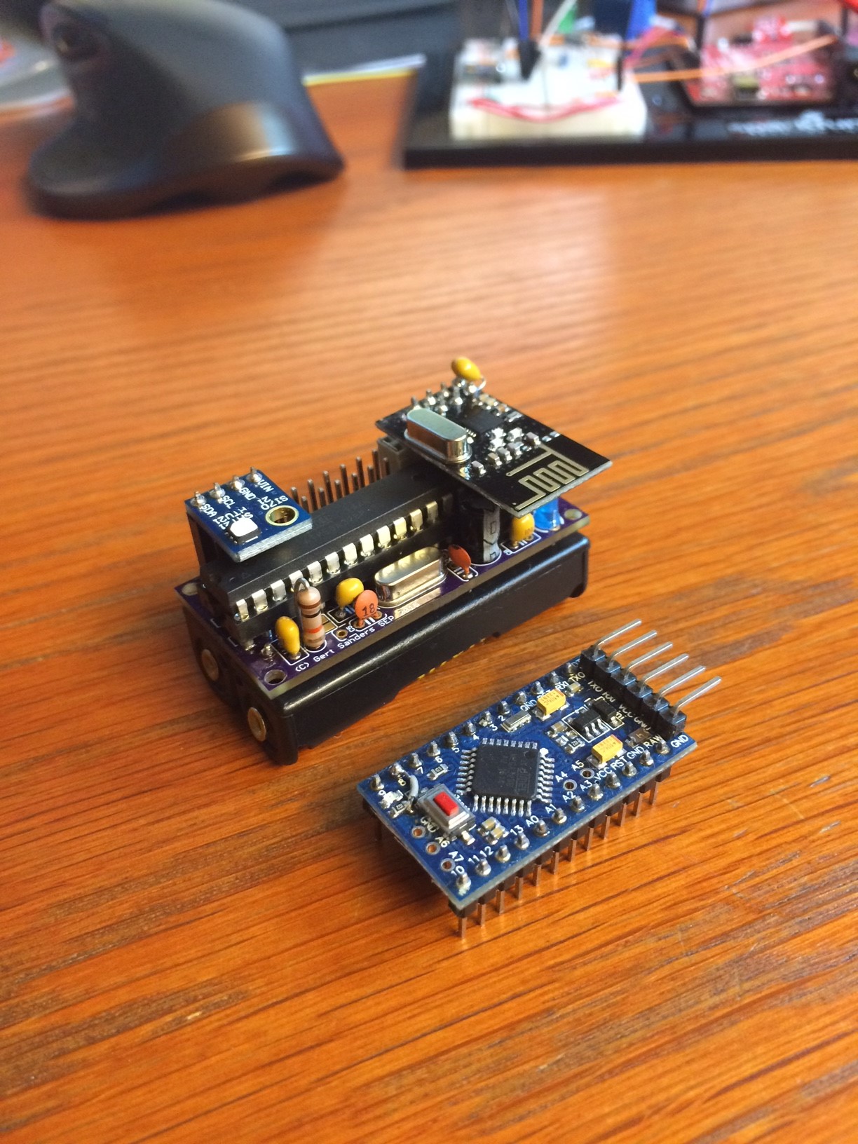
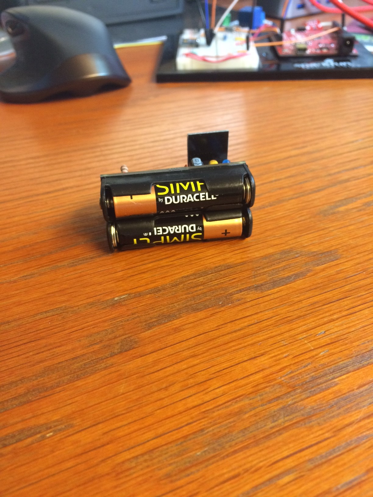
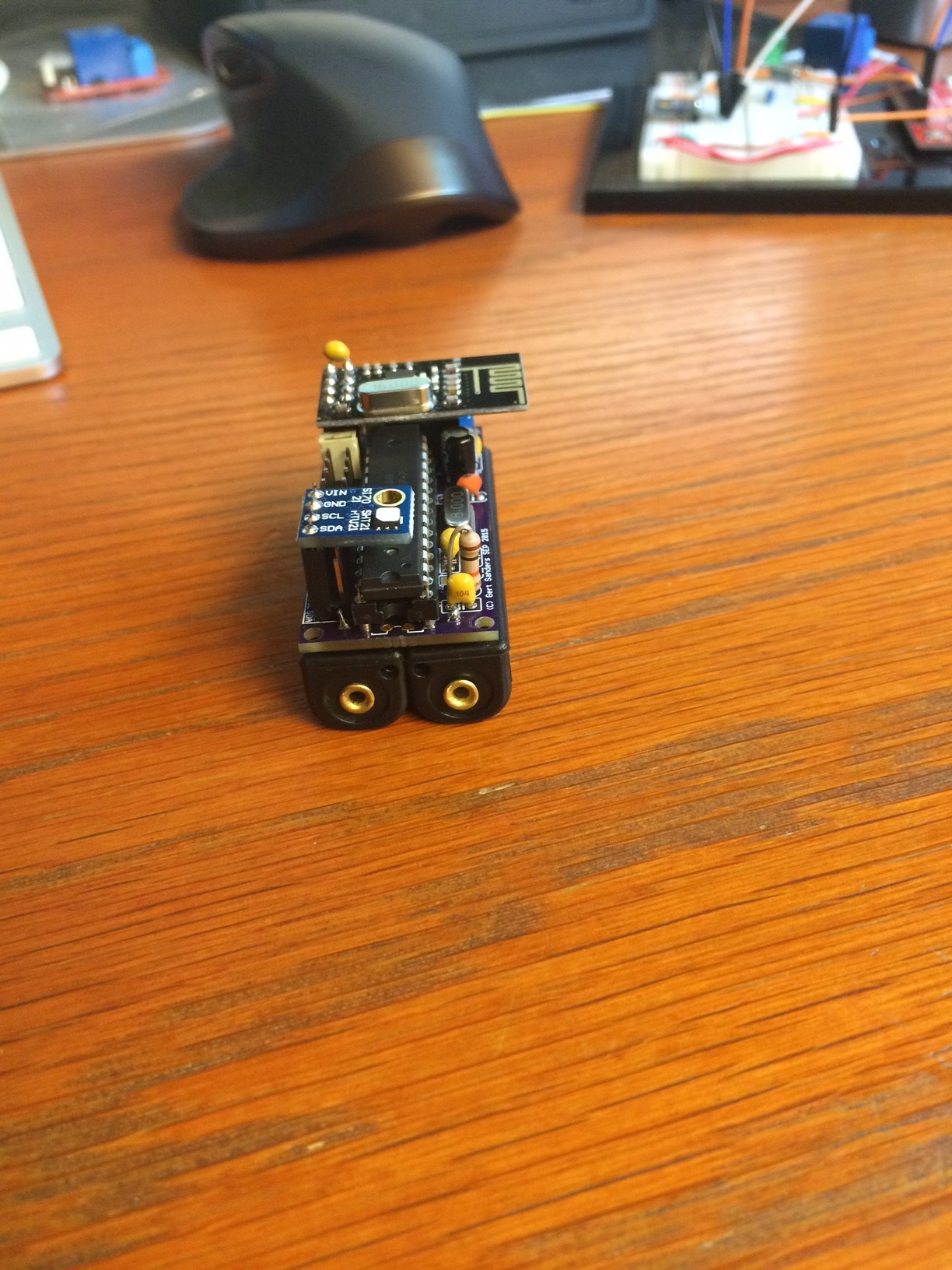
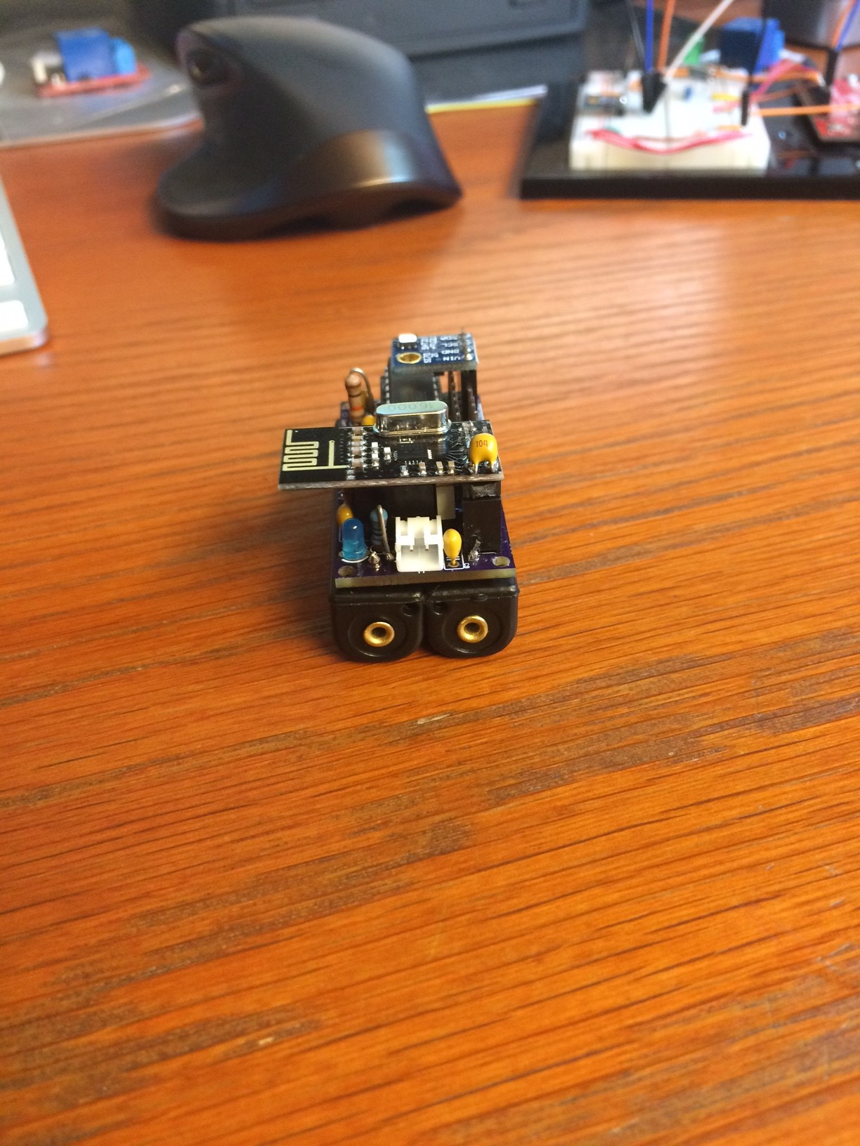
Second variant with the same board. This one actually sends it's messages better (no more st:fail's):
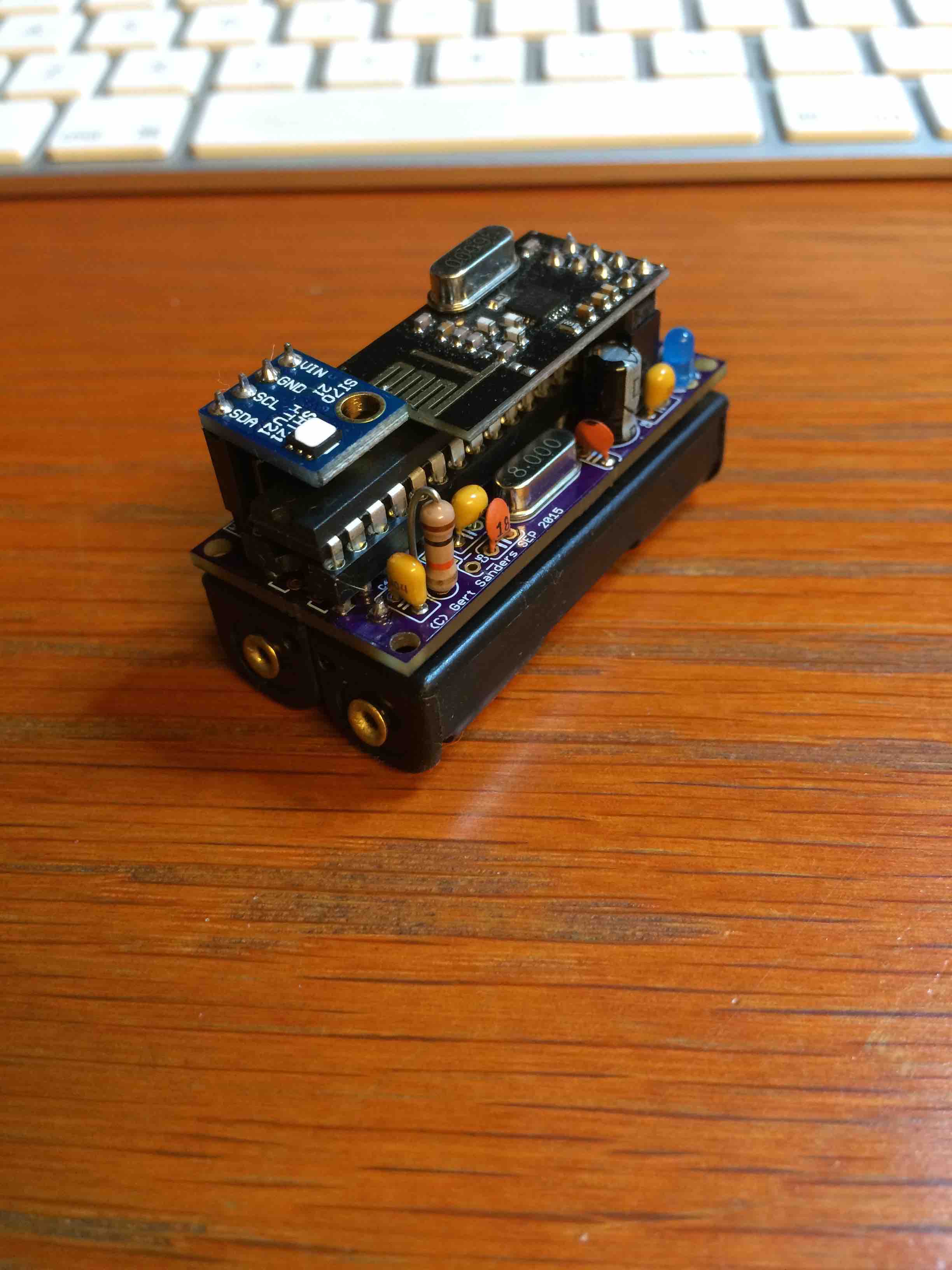
And it's nice and compact. Now I need to find a nice ventilated little box to protect them from dust.
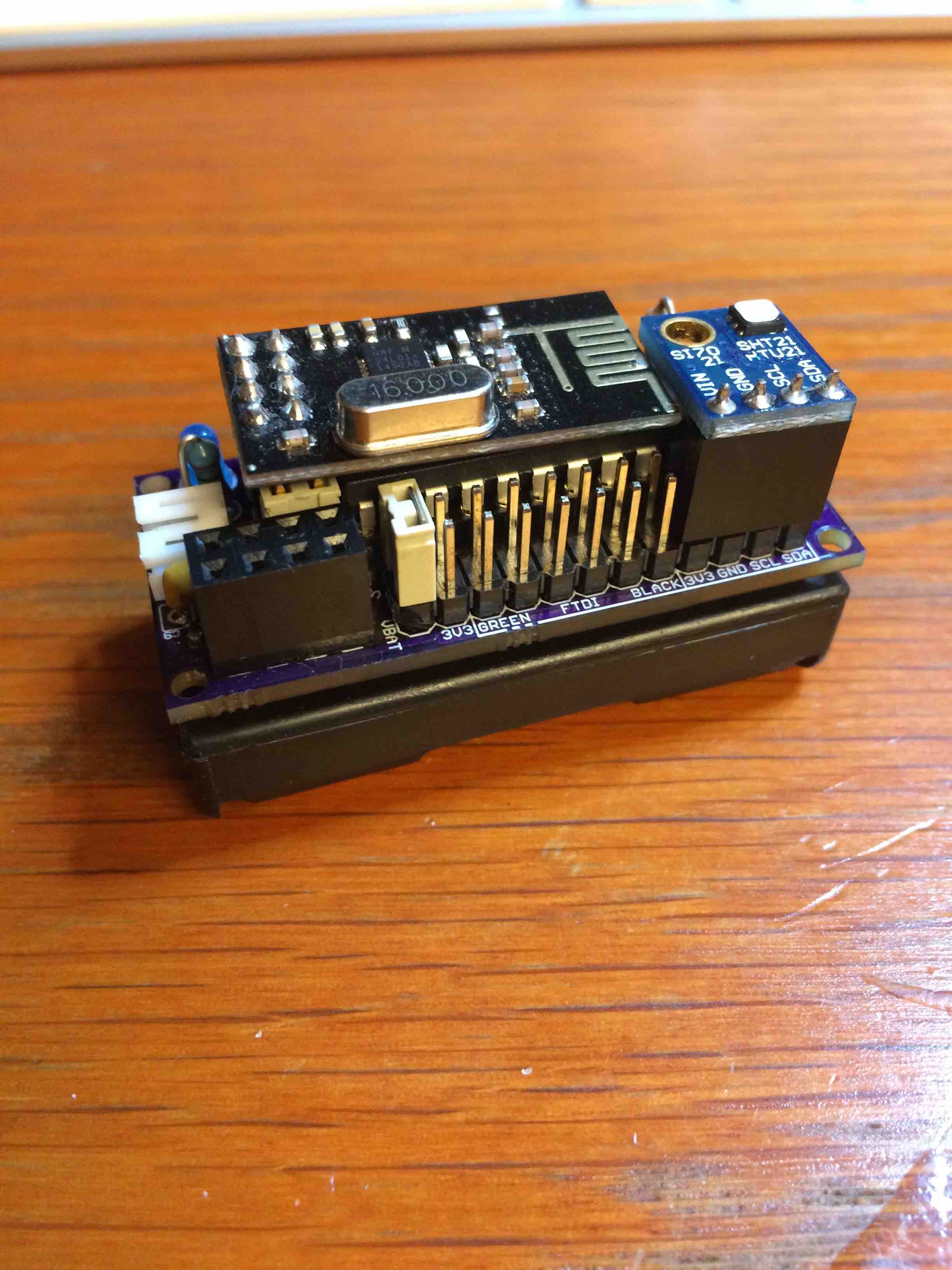
This board is now tested and shared on OSHPark: https://oshpark.com/shared_projects/unP8BmuI
Component values are mentioned in the brd file. I will add a BOM in Excel format later.
Hello! It looks like you're interested in this conversation, but you don't have an account yet.
Getting fed up of having to scroll through the same posts each visit? When you register for an account, you'll always come back to exactly where you were before, and choose to be notified of new replies (either via email, or push notification). You'll also be able to save bookmarks and upvote posts to show your appreciation to other community members.
With your input, this post could be even better 💗
Register Login